FANUC Series 30i/300i/300is-MODEL A. Machining Center System. User's manual - page 142
 

  Index      Manuals     FANUC Series 30i/300i/300is-MODEL A. Machining Center System. User's manual (B-63944EN/03)


Search            copyright infringement  


Content      ..     140      141      142      143     ..


FANUC Series 30i/300i/300is-MODEL A. Machining Center System. User's manual - page 142


3.MANUAL OPERATION

 OPERATION 

B-63944EN/03


- 1092 - 

 CAUTION 

1  When the Linear scale with distance-coded 

reference marks (serial) is used, please set bit 3 
(SDCx) of parameter No.1818 to 1. 

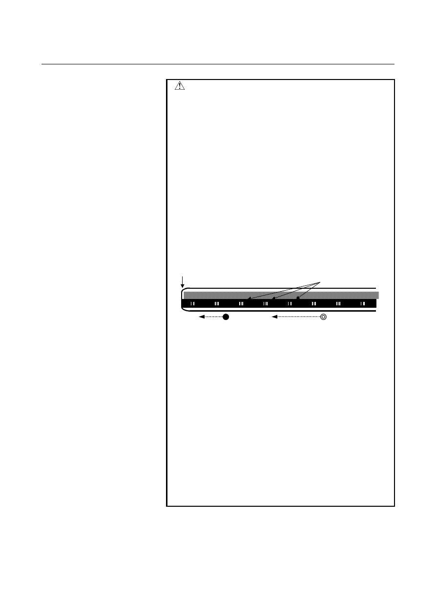
2  On the Linear scale with distance-coded reference 

marks (serial), the axis does not stop until three 
reference marks are detected.    If this procedure is 
started at the position near the scale end, CNC can 
not detect three reference marks and the axis does 
not stop until over travel alarm occurs. Please care 
to start at the position that has enough distance 
from scale end. 


And if establishment of reference position is failed, 
the establishment is retried. Then axis does not 
stop until still more three reference marks are 
detected. So please set the maximum move 
amount (detection unit : parameter No.14010) not 
to reach the scale end. 

Scale end


Reference marks


Start point (Bad) 

Start point (Good) 


3  On flexible synchronization control mode, 

reference position can't be established. 

4  Straightness compensation function 
 

When the reference point establishment of moving 
axis is executed after the establishment of 
compensation axis, the compensation axis is 
moved by straightness compensation amount 
when the reference point of moving axis is 
established. 

5  It is not available to use this function and the 

temporary absolute coordinate setting together. 

6  The reference point cannot be established during 

twin table synchronous operation or single 
operation. 

7  Angular axis control cannot be performed together 

with synchronous control, composite control, or 
superposition control.   


B-63944EN/03

 OPERATION 

3.MANUAL OPERATION


- 1093 - 

3.12 

MANUAL HANDLE RETRACE 


Overview 

In this function, the program can be executed both forward and 
backward with a manual handle (manual pulse generator) under 
automatic operation. 
Therefore, errors of a program, interference, and so on can be checked 
easily by working a machine actually. 


 - Checking mode 

In this mode, the program can be executed forward and backward and 
the program can be checked. 
To change to the checking mode, it is necessary to change the mode to 
the memory mode (MEM mode), and the checking mode signal 
MMOD<Gn067.2> is set to "1". This function makes the data to 
execute the program backward when the program is executed forward 
in the checking mode. 
To work a machine synchronizing with a pulse generated by a manual 
handle in the checking mode, the manual handle check signal MCHK 
<Gn067.3> is set to "1" in addition to the above-mentioned. As a 
result, it becomes possible to check the program with a manual handle. 


NOTE 


During the checking mode, it is not possible to 
change the parameter and offset. 


  - Forward movement with a manual handle 

The "forward movement" is that the program is executed forward by 
turning a manual handle in the positive direction (when the manual 
handle check signal is set to "1".) or in no relation to rotation of a 
manual handle (when the manual handle check signal is set to "0".). 
When the manual handle check signal is set to "1", the execution 
speed of the program is proportional to the number of rotations of a 
manual handle. The program is executed forward rapidly when a 
manual handle is turned to the positive direction rapidly. And, the 
program is executed forward slowly when a manual handle is turned 
to the positive direction slowly. The distance magnification traveled 
per pulse from manual handle can be switched as same as a usual 
manual handle feed function. 
When the manual handle check signal is set to "0", the execution of 
the program is controlled as same as an automatic operation. 
 

3.MANUAL OPERATION

 OPERATION 

B-63944EN/03


- 1094 - 

 - Backward movement 

The "backward movement " is that the program executed forward once 
is executed backward by turning a manual handle in the negative 
direction. 
The program can be executed backward only for the block executed 
forward. And, the number of blocks for it is about 190 blocks. This 
block number changes by the content of the commanded program. 
The program is executed backward rapidly when a manual handle is 
turned to the negative direction rapidly. And the program is executed 
backward slowly when a manual handle is turned to the negative 
direction slowly. The distance traveled per pulse from manual handle 
can switch magnification as well as a usual manual handle feed. 
 

NOTE 


In the system which exceeds 4 paths and 20 
axes, the maximum number of blocks which can 
move backward becomes about 97 blocks.   


Explanation 
  - Control by the manual handle 
    Program execution start 

The checking mode signal MMOD<Gn067.2> is set to "1" in the 
memory mode (MEM mode) in order to change the checking mode. 
Then, the program execution is begun by turning ST signal from "1" 
to "0". 
If the manual handle check signal MCHK <Gn067.3> is set to "1" at 
this time, the execution of the program is controlled by a manual 
handle. The program is executed synchronizing with rotation of a 
manual handle.   
When a manual handle check signal MCHK<Gn067.3> is set to "0", it 
is controlled as usual execution.   
When check mode signal MMOD<Gn067.2> is set to "1" during the 
operation of the program, it is enabled a check mode from the block 
that next buffering is done. 
That is, even if check mode signal set to "1", check mode is not 
always enabled at once. 
When check mode is enabled, check mode confirmation signal 
MMMOD<Fn091.3> is set to "1". 


NOTE 


After the signal MMOD is turned to "0" during the 
execution of the program, the program cannot be 
executed forward and backward. 


B-63944EN/03

 OPERATION 

3.MANUAL OPERATION


- 1095 - 

      Control with the manual handle 

The value of the parameter No.6410 and the scale factors decide the 
moving speed of the machine by one pulse generated by a manual 
handle. 
When a manual handle is turned, the actual movement speed of the 
machine is as follows. 
[Feedrate command value] 

×

 [Number of the handle pulse per a 

second] 

×

 [Handle magnification] 

×

 ([Parameter setting value]/100) 

×

 (8/1000) 

(mm/min or inch/min) 
Example) When feedrate command value is 30mm/min, handle 
magnification is 100, parameter No.6410 is set to 1 and manual pulse 
generator is rotated at 100 pulse/rev, the feedrate of axis is decided as 
follow. 
[Feedrate]=30[mm/min] 

×

 100[pulse/s] 

×

 100 

×

 (1/100) 

×

 (8/1000)[s] 

=24[mm/min] 

 
When the feedrate exceeds the override 100% feedrate by turning a 
manual handle rapidly, the feedrate is clamped at the speed of override 
100%. That is, if the pulse of the following formula exceeds "1", the 
feedrate is clamped. 
[Number of the handle pulse per a second] 

×

 [Handle magnification] 

×

 ([Parameter setting value]/100) 

×

 (8/1000) 

The rapid traverse feedrate is clamped at 10%. However, the feedrate 
of the rapid traverse is clamped at 100% when bit 0 (HDRPD) of 
parameter No.6400 is set to "1". 
And if parameter No.6405 is set to an optional value, it can be 
clamped to override by nearly optional value. 
When the parameter No.6405 is set to larger value than "100", it is 
clamped to nearly 100%. 
When parameter No.6405 is set to "0", the setting of bit 0 (RPO) of 
parameter No.6400 becomes valid. 
The single block signal and the feed hold signal are effective in the 
checking mode. When the execution of a program is stopped by the 
single block stop or the feed hold stop, it is necessary to turn ST signal 
from "1" to "0" in order to restart the program. 
In the block with the movement and the block of dwell, the execution 
speed of the program can be controlled by turning a manual handle. 
As for the block of neither movement nor dwell such as the block of 
only address M, S, T, and F, the program advances to the following 
block even if a manual handle does not turn. 
The rotation of the spindle does not synchronize with a pulse of a 
manual handle. During the checking mode, the spindle rotates at the 
specified rotation speed. As for the feed per revolution, a program is 
executed at the feedrate which was converted from the rotation speed 
of the spindle to the corresponding feed per minute inside CNC. 


NOTE 


The manual handle used by this function is always 
the first. The 2nd and 3rd manual handle cannot be 
used in this function. 

3.MANUAL OPERATION

 OPERATION 

B-63944EN/03


- 1096 - 


      Forward movement and backward movement with a manual handle 

The program is executed forward when a manual handle is turned to 
the positive direction. And, the program is executed backward when a 
manual handle is turned to the negative direction. 
The program is executed backward as soon as a manual handle is 
turned to the negative direction in executing the program forward.   
When a manual handle keeps being turned in a negative direction, the 
program is executed backward and the execution stops in the block of 
O number. Then, if a manual handle is turned to the positive direction, 
the program is executed forward again. 
Even if a manual handle controls the program execution, the program 
is executed forward in no relation to a pulse generated by a manual 
handle on setting the manual handle check signal to "0". 
 

    Program end 

When the block of M2 or M30 is executed, the manual handle retrace 
ends. It is not possible to execute the program backward from the 
block of M2 or M30. 
When the execution of the program ends, RESET signal must be set to 
"1", and the checking mode signal and the manual handle check signal 
must be set to "0". 
In 2 path control system, FIN signal must not be set to "1" when the 
block of M2 or M30 is executed in only one of paths. After the block 
of M2 or M30 has been executed in both paths, FIN signal is set to "1". 
(Except for the block of waiting M code is commanded before M2 or 
M30 in both paths.) 
 

  - Notice of the operation 

Dry-run can not operate during the checking mode. Dry-run signal 
must be set to "0". 
Automatic operation starts immediately with the feedrate commanded 
by the program, when the checking mode signal or the synchronous 
operation with handle signal is turned off during executing the 
program in the checking mode.   
The edit of the program and the change of the parameter and the offset 
must not be done.   
 

  - Backward movement of each code 

All modal information of G, T, S-code is memorized in executing the 
program forward. And, the memorized data of the modal G, T, S-code 
are used in executing the program backward.   
As for M-codes, they are grouped and the modal information is 
managed by parameter No.6411 to 6490. Therefore, M-code can be 
executed backward according to the information. As for the modal 
information of the M-code, a change in each group is memorized in 
the execution data. 
As for the codes except for G, M, S, and T, the same code is output   
between forward movement and backward movement. 
 

B-63944EN/03

 OPERATION 

3.MANUAL OPERATION


- 1097 - 

 - G-code 

If G-code that changes modal information is commanded in backward 
movement, the modal information of previous block is executed. 
Example) 
 N1G99; 
 N2G01X_F_; 
 N3X_Z_; 
 

N4G98; ..................... backward movement starts from this block 

 N5X_Y_Z_; 
If backward movement starts from N4 block, the modal information is 
changed from G98 to G99 and G99 is executed from N3. 
G-code with a movement is traced along the route opposite to forward 
movement. 
G-code that can be command in executing the program backward is as 
follows. 
The other G-codes cannot be command in executing the program 
backward. 
The G-codes in the G-code system B and C also can be used. 
 
Lathe system 
  G00 G01 G02 G03 G04 G22 G23 
  G25 G26 G28 G30 G40 G41 G42 
  G50 G53 G65 G70 G71 G72 G73 
  G75 G80 G83 G85 G87 G89 G90 
  G94 G96 G97 G98 G99 
 

  (G-code system A) 

 
Machining center system 
  G00 G01 G02 G03 G04 G22 G23 
  G25 G26 G28 G30 G40 G41 G42 
  G43 G44 G49 G53 G65 G73 G76 
  G80 G81 G82 G83 G85 G86 G87 
  G88 G89 G82 G94 G95 G96 G97 
 

NOTE


1  In Small-Holl Pecking Drilling Cycle(G83), 

backward movement is prohibited. 

2  In forward movement of Boring Cycle(G88), the 

sequence of actions at bottom of holl is shown as 
follows (dwell -> stop of spindle motor -> hold 
state). But in backward movement, that is (rotation 
of spindle -> hold state -> dwell after restart). 


3.MANUAL OPERATION

 OPERATION 

B-63944EN/03


- 1098 - 

 - M-code 

If there is M-code in the same group is commanded in previous blocks, 
modal information of the M-code, commanded at the last in previous 
blocks, is output. 
If no M-code is commanded in previous blocks, the M-code set to the 
first parameter in the same M-code group is output. 
If M-code is not set to group M-code in parameter, the same M-code 
is output in backward movement. 
If the parameter RVN(6400#5) is set to "1", the backward movement 
is prohibited when the M-code, which is not set to group M-code, is 
commanded in backward movement. 
 

NOTE


When setting the parameter RVN, backward 
movement prohibition is enabled except the 
M-code which was set in the grouping but 
backward movement can be enabled for the 
following M-code exceptionally. 


1. Subprogram Call by M98/M99. 


2. Subprogram Call using an M code 


3. Macro Call using an M code 


4. Waiting M code 

 5. 

M0 

 
Example) Output of M-codes that are set to groups by parameters in 
backward movement 
Setting of parameters: 
    No.6400#2=1, #3=0 (5 M-codes/group and 16 groups) 
  No.6411=100 
  No.6412=101 
  No.6413=102 
  No.6414=103 
  No.6415=104 
  No.6416=200 
  No.6417=201 
  No.6418=202 
  No.6419=203 
  No.6420=204 
Program O10 is executed in forward movement from N1 to N15 and 
backward movement is executed from N15. In backward movement, 
the output of M-codes is shown as next table. 


Forward movement

Backward movement 

O10;  


N1G4X1.;  


N2M101; M101 

M100 

(*1) 

N3G4X1.;  


N4M204; M204 

M200 

(*1) 

N5G4X1.;  


N6M104; M104 

M101 

(*2) 

N7G4X1.;  


Group A

Group B

B-63944EN/03

 OPERATION 

3.MANUAL OPERATION


- 1099 - 


Forward movement

Backward movement 

N8M300; M300 

M300 

N9G4X1.;  


N10M200; M200 

M204 

(*1) 

N11G4X1.;  


N12M0; M0 

M0 

(*3) 

N13G4X1.;  


N14M102; M102 

M104 

(*2) 

N15G4X1.; 

Backward movement starts from this block 

M2;  


*1  No M-code in the same group is commanded before this block, 

so the M-code, which is set in the 1st. parameter of the same 
group, is output. 

*2  M-code in the same group is commanded before this block, so 

the M-code, which is commanded at the last before this block, is 
output. 

*3  M-code is not set to group M-code, so the same M-code is 

output. 


  - S and T-code 

A modal value of the previous block is output. 
When movement command and S-code or T-code is commanded in 
the same block, the timing of the output of the S-code and T-code is 
different. Because, the timing where S-code and T-code are output at 
the forward movement is different from that at the backward 
movement. By setting bit 7 (STO) of parameter No.6401 to "1", the 
timing of the output of S and T code at the forward movement is the 
same as the one at the backward movement.   
 
Example) 
 

T-code output timing at the backward movement 


T-code is output as follows when the program proceeds 
backward after the forward movement to N8 block. 


Backward movement 


Forward 

movement 

Parameter 

STO=0 

Parameter 

STO=1 

O1000;  


N1G98G00X0Z0; 


Default T output 

N2G00X-10.T11; 

T11 output 

Default T output 


N3G00X100.;  


T11 

output 

N4G00X10.Z20.T22; 

T22 output 

T11 output 

No T code output 

N5G00X30.Z30.;  


N6G00X-10.Z-20.;  


T22 

output 

N7G00X50.Z40.T33; 

T33 output 

T22 output 

T33 output 

N8G04X5.; 


(Backward start) 

(Backward start) 

M30;  


The “Default T” means a T-code status at N1 block in forward 
movement. If the status is    T0, “T0” signal is output as “Default T” 
in the backward movement. 


Content      ..     140      141      142      143     ..