FANUC Series 30i/300i/300is-MODEL A. Machining Center System. User's manual - page 140
 

  Index      Manuals     FANUC Series 30i/300i/300is-MODEL A. Machining Center System. User's manual (B-63944EN/03)


Search            copyright infringement  


Content      ..     138      139      140      141     ..


FANUC Series 30i/300i/300is-MODEL A. Machining Center System. User's manual - page 140


3.MANUAL OPERATION

 OPERATION 

B-63944EN/03


- 1076 - 

3.9.5 

Table Horizontal Direction Handle Feed / Table Horizontal 

Direction JOG Feed / Table Horizontal Direction Incremental 

Feed 


Overview 

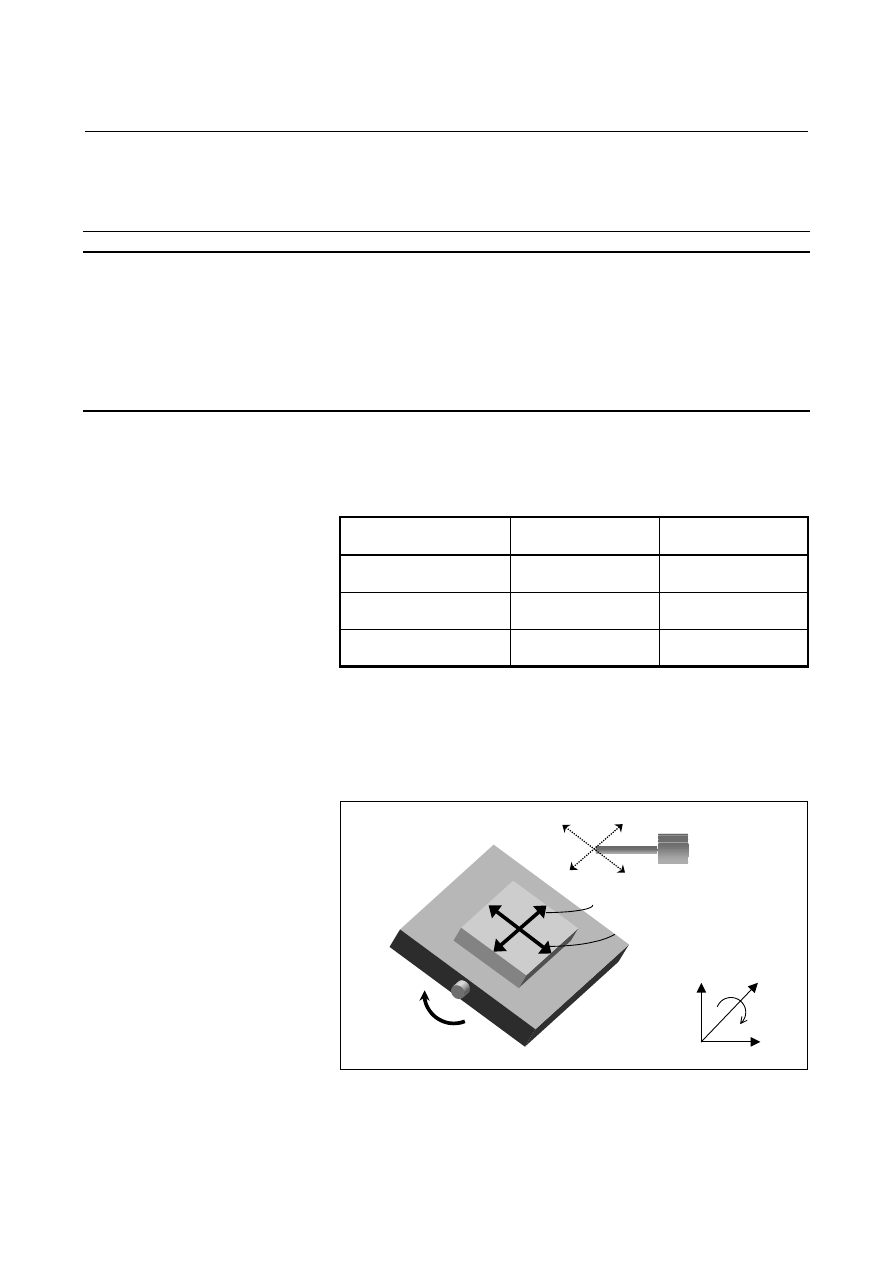
In the table horizontal direction handle feed, table horizontal direction 
JOG feed, and table horizontal direction incremental feed, the tool is 
moved in the table horizontal direction. 
If bit 1 (FLL) of parameter No. 12320 is set to 1, the tool or table is 
moved in the latitude or longitude direction determined by the 
table-based vertical direction vector. 
 

Explanation 
  - Table horizontal direction 

There are two table horizontal directions, which are perpendicular to 
the table vertical direction (see the previous section). 
 

Parameter No.19697 

Table horizontal 

direction 1 

Table horizontal 

direction 2 

1  (The reference tool 

direction is +X.) 

+Y direction 

+Z direction 

2  (The reference tool 

direction is +Y.) 

+Z direction 

+X direction 

3  (The reference tool 

direction is +Z.) 

+X direction 

+Y direction 

 
This table shows the table horizontal directions that may be taken 
when the angles of all the rotation axes for controlling the table are 0 
degree. 
As the rotation axes for controlling the table rotate, the table 
horizontal direction changes according to the rotation axis angle. 


B


B


Z


Y

X

Table horizontal direction 2

Table horizontal direction 1


B-63944EN/03

 OPERATION 

3.MANUAL OPERATION


- 1077 - 


(Example)  When the table rotation axis is the B-axis, and the table vertical direction 

is the Z-axis direction 


B


Z


Y

X

Table horizontal direction 2

Table horizontal 

direction 1 

X


Y

Z

B

B

Table vertical direction 


  - Latitude and longitude directions 

When bit 1 (FLL) of parameter No. 12320 is set to 1, the feed 
direction is defined as follows: 
Let a vector perpendicular to a plane formed by the table-based 
vertical direction vector (

T

r

) and normal axis direction vector (

P

r

(parameter No. 12321) be the table-based horizontal direction 1 
(longitude direction) vector (

1

r

R

).  When tool axis right-angle 

direction 1 is selected, a movement in the positive direction means a 
movement in this vector direction, and a movement in the negative 
direction means a movement in the direction opposite to the vector 
direction.  (Longitude direction feed) 
Equation:  

T

P

R

r

r

r

×

=

1


Let a vector perpendicular to the table-based vertical direction vector 
(

T

r

) and table-based horizontal direction 1 (longitude direction) vector 

(

1

r

R

) be the table-based horizontal direction 2 (latitude direction) 

vector (

2

R

r

).  When tool axis right-angle direction 2 is selected, a 

movement in the positive direction means a movement in this vector 
direction, and a movement in the negative direction means a 
movement in the direction opposite to the vector direction.    (Latitude 
direction) 
Equation:  

1

2

R

T

R

r

r

r

×

=


When table-based vertical direction vector (

T

r

) is parallel to the 

normal axis direction vector (

P

r

) (parameter No. 12321) (when the 

angle between them is not greater than the setting of parameter No. 
12322), tool axis right-angle direction 1 and tool axis right-angle 
direction 2 are assumed as follows: 


Parameter 

No. 12321

Normal axis 

direction 

Table-based 

horizontal direction 1 

Table-based 

horizontal direction 2

1   

+X

 direction

+Y

 direction


+Z

 direction


2   

+Y

 direction

+Z

 direction


+X

 direction


+Z

 direction

+X

 direction


+Y

 direction


3.MANUAL OPERATION

 OPERATION 

B-63944EN/03


- 1078 - 

If 0 is set in parameter No. 12321, the normal axis direction is set to 
the tool axis direction. 

If a value other than 0 to 3 is specified in parameter No. 12321, alarm 
PS5459 is issued. 


Table-based vertical 

direction: T 

Table-based horizontal 

direction 2 (latitude 

direction): R2 

Table-based horizontal 

direction 1 (longitude 

direction): R1 

Normal axis direction: P


  - Table-based horizontal direction feed in the tilted working plane command mode 

If bit 0 (TWD) of parameter No. 12320 is set to 1, the feed direction of 
the table-based horizontal direction feed in the tilted working plane 
command mode is defined as follows: 

Table-based horizontal direction 1:  X direction in the feature 
coordinate system of the tilted working plane command 
Table-based horizontal direction 2:  Y direction in the feature 
coordinate system of the tilted working plane command 


  - Table horizontal direction handle feed 

The table horizontal direction handle feed is enabled when the 
following four conditions are satisfied: 
<1>  Handle mode is selected. 
<2> Both the tool axis right-angle direction feed mode signal 

(RGHTH) and the table base signal (TB_BASE) are set to 1. 

<3> The state of the first manual handle feed axis selection signals 

(HS1A - HS1E) to make the table horizontal direction handle 
feed mode effective is set in parameter No.12311 or No.12312. 

<4>  The value of parameter No.12311 or No.12312 matches the first 

manual handle feed axis selection signals (HS1A - HS1E). 


    Amount of movement 

When the manual pulse generator is rotated, the tool is moved in the 
table horizontal direction by the amount of rotation. 
 

    Feedrate clamp 

The feedrate is clamped so that the speed of each moving axis dose 
not exceed the manual rapid traverse rate (parameter No.1424).  
Handle pulses generated while the clamp feedrate is exceeded are 
ignored. 
 

B-63944EN/03

 OPERATION 

3.MANUAL OPERATION


- 1079 - 

  - Table horizontal direction JOG feed/table horizontal direction incremental feed 

The table horizontal direction JOG feed or table horizontal direction 
incremental feed is enabled when the following three conditions are 
satisfied: 
<1>  JOG mode or incremental feed mode is selected. 
<2> Both the tool axis right-angle direction feed mode signal 

(RGHTH) and the table base signal (TB_BASE) are set to "1". 

<3>  The feed axis direction selection signal (+Jn, -Jn (where n = 1 to 

the number of controlled axes)) is set to "1" for the axis 
corresponding to the direction that is perpendicular to the 
direction specified by parameter No.19697. 
Ex.) No.19697 = 3 (+Z-axis direction); X-, Y-, and Z-axes are 

the 1st, 2nd, and 3rd axes respectively. 


+J1  : Table horizontal direction 1 + 


-J1  : Table horizontal direction 1 - 


+J2  : Table horizontal direction 2 + 


-J2  : Table horizontal direction 2 - 


    Feedrate 

The feedrate is the dry run rate (parameter No.1410).  The manual 
feedrate override feature is available. 
If bit 2 (JFR) of parameter No. 12320 is set to 1, the feedrate is the jog 
feedrate (parameter No. 1423) of a driven feed axis direction selection 
signal.    The manual feedrate override feature is available. 
 

    Feedrate clamp 

The feedrate is clamped so that the speed of each moving axis dose 
not exceed the manual rapid traverse rate (parameter No.1424). 
 

Note 

To perform a three-dimensional handle feed, the manual handle 
feed option is required.  To perform three-dimensional handle 
interrupt, the manual handle interrupt option is required. 

When a three-dimensional handle interrupt is performed, rotation 
axis command execution must not be in progress in automatic 
operation. 

3  When the manual reference position return mode is selected, 

three-dimensional manual feed is not enabled. 

When the offset value specified for the tool length offset function 
is used for tool center point rotation feed (when bit 2 (LOD) of 
parameter No. 19746 is set to 1), the controlled point should 
generally be shifted.    (Set bit 5 (SVC) of parameter No. 19665 
to 1.) 
In this case, specify the tool length with a radius value. 

3.MANUAL OPERATION

 OPERATION 

B-63944EN/03


- 1080 - 

3.10 

DISTANCE CODED LINEAR SCALE INTERFACE 


Overview 

The interval of each reference marks of distance coded linear scale are 
variable. Accordingly, if the interval is determined, the absolute 
position can be determined. The CNC measures the interval of 
reference marks by axis moving of short distance and determines the 
absolute position. Consequently the reference position can be 
established without moving to reference position. 


10.02

10.04

20.02

20.00

20.00

Reference mark 1 Reference mark 2Mark 1 

Mark 2 

Mark 1 


Fig. 3.10 (a)    Example of distance coded linear scale 

 
This is an optional function. 
 

3.10.1 

Procedure for Reference Position Establishment 


Procedure 

(1)  Select the JOG mode, and set the manual reference position 

return selection signal ZRN to "1".   

(2)  Set a direction selection signal(+J1,-J1,+J2,-J2,…) for a target 

axis. 

(3)  The axis is fed at a constant low speed (reference position return 

FL feedrate specified by parameter (No.1425) setting). 

(4)  When a reference mark is detected, the axis stops, then the axis is 

fed at a constant low speed again. 

(5)  Above (4) is executed repeatedly until two, three or four 

reference marks are detected.  And absolute position is 
determined and reference position establishment signal 
(ZRF1,ZRF2,ZRF3, …) turns to "1". 


(A number of reference marks is determined by bit 2 (DC2x) and 
1 (DC4x) of parameter No.1802.) 


Even when the direction selection signal (+J1, -J1, +J2, -J2,...) is set to 
"0" while steps (2) to (5) are being performed, the feedrate operation 
does not stop, and the operation for establishing a reference position is 
carried out continuously. 


B-63944EN/03

 OPERATION 

3.MANUAL OPERATION


- 1081 - 

The timing chart for this procedures is given below. 

JOG


ZRN


+J1


Reference mark


ZRF1


Feedrate


FL rate 

FL rate 

FL rate 


Fig. 3.10.1 (a)    Timing chart for reference position establishment 


  - Procedure for establishing a reference position through automatic operation 

If an automatic reference position return (G28) is specified before a 
reference position is not established, steps (3) to (5) above are 
performed automatically. 
After the reference position is established, the automatic reference 
position return is performed. 
 

  - Stopping the operation for establishing a reference position 

The operation for establishing a reference position is stopped if any of 
the following operations is performed in steps (3) to (5), described 
above. 

 Reset 


Setting the feed axis direction selection signal (+J1, -J1, +J2, -J2, 
etc.) to 0 

 
If any of the following operations is performed during the operation of 
automatic reference position return (G28) before a reference position 
is not established, the operation for establishing a reference position 
stops: 

 Reset 

  Performing feed hold during movement from an intermediate 

position 

 
If the operation for establishing a reference position is stopped by an 
operation other than a reset, the operation for establishing a reference 
position must be reset and resumed. 
 

3.MANUAL OPERATION

 OPERATION 

B-63944EN/03


- 1082 - 

3.10.2 

Reference Position Return 

 
(1)  When the reference position is not established and the axis 

moved by turning the feed axis direction signal 
(+J1,-J1,+J2,-J2,...) to "1" in REF mode, the reference position 
establishment procedure is executed. 

(2)  When the reference position is already established and the axis is 

moved by turning the feed axis direction signal 
(+J1,-J1,+J2,-J2,...) to "1" in REF mode, the axis is moved to the 
reference point without executing the reference position 
establishment procedure. 

(3)  When the reference position is not established and the reference 

position return command (G28) is executed, the reference 
position establishment procedure is executed. The next 
movement the axis depends on the setting of parameter RFS 
(No.1818#0). 

(4)  When the reference position is already established and the 

reference position command (G28) is executed, the movement of 
the axis depends on the setting of bit 1 (RF2) of parameter 
No.1818. 


3.10.3 

Distance Coded Rotary Encoder 

 
In case of setting a rotary axis, if bit 3 (DCRx) of parameter No.1815 
is set, the setting axis is regarded as being equipped with a distance 
coded rotary encoder. 
In case of distance coded rotary encoder, the marker interval may be 
different from parameter setting value. (a-b section of the following 
figure)  When the reference point return is executed through this 
section, it is not able to establish the reference point. Therefore, in 
case of distance coded rotary encoder, if the reference point return is 
started for B point from A point of below figure, the reference point is 
not established yet at B point. The reference point return is re-started 
for C point. The reference point return procedure is finished at C 
point. 

9.64 

9.98

9.96

19.66 

20.02

20.02

20.02

9.94

20.00

20.00

20.00

A

C

a


  When the reference point return procedure is executed, the 

coordinate value are rounded in 0 to 360 degree, even if Machine 
coordinate values are linear axis type. 

B-63944EN/03

 OPERATION 

3.MANUAL OPERATION


- 1083 - 


In case of distance coded rotary encoder, only the measurement 
by three points or four points is possible. (bit 2 (DC2) of 
parameter No.1802 is disregarded as 0.) 


3.10.4 

Axis Synchronization Control 


Requirements when this function is used with axis synchronization control 
axes 

When this function is used with axis synchronization control axes, the 
distance coded linear scale used for the master axis and that used for 
the slave axis must have reference marks placed at identical intervals. 
(Set identical values in parameters Nos. 1821 and 1882 for both the 
master and slave axes.) 
This function does not work unless the use of this function is specified 
for both the master and slave axes (bit 2 (DCL) of parameter No. 1815 
is 1). 
Also, in all parameters related to this function, except parameter No. 
1883, 1884 (distance from the scale zero point to reference position 1, 
2), set identical values for both the master and slave axes. 
If a parameter value for the master axis differs from the corresponding 
parameter value for the slave axis, alarm SV1051 is issued. 
 

NOTE 


When this function is used with axis 
synchronization control axes for which the 
operation mode is switched between 
synchronization operation and normal operation, 
this function is enabled only if the synchronization 
select signal (SYNC1, SYNC2, ...<Gn138>) is 1. 
(During establishment of a reference position, the 
synchronization select signal status must be 
maintained.) 


Reference position establishment with axis synchronization control axes 

With axis synchronization control axes, a reference position is 
established as follows. When a reference mark for the master or slave 
axis is detected, a stop takes place temporarily. Then, a feed operation 
is performed again at the reference position return FL feedrate. This 
sequence is repeated until a reference mark is detected three or four 
times for both the master and slave axes. Then the absolute position is 
calculated for both the master and slave axes, and the reference 
position establish signals ZRF1, ZRF2, ... <F120> are set to 1. 
After the reference position has been established by the above 
operation, a synchronization error is corrected. (Checking for 
excessive synchronization error alarm 2 is made even during reference 
position establishment.) 


Content      ..     138      139      140      141     ..