FANUC Series 30i/300i/300is-MODEL A. Machining Center System. User's manual - page 141
 

  Index      Manuals     FANUC Series 30i/300i/300is-MODEL A. Machining Center System. User's manual (B-63944EN/03)


Search            copyright infringement  


Content      ..     139      140      141      142     ..


FANUC Series 30i/300i/300is-MODEL A. Machining Center System. User's manual - page 141


3.MANUAL OPERATION

 OPERATION 

B-63944EN/03


- 1084 - 


Scale end


Reference mark


(1)

(2)

(3)

(a) 

(b) (c) 

Master axis 

Slave axis 

Start point 

End Point 

(Example of 3 points measurement system)


In the above example, the following sequence is executed. 
a.  When the reference mark (1) of the master axis is detected, both 

master axis and slave axis stop. 

b.  Both the axes begin to move again at a reference position return 

FL feedrate. 

c.  When the reference mark (a) of the slave axis is detected, both 

axes stop again. 

d.  Both the axes begin to move again at FL feedrate. 
e.  Both axes repeat the operation until all point ((2) -> (b) ->(3) -> 

(c)) are detected. 

f. 

When the slave axis detects the third reference mark (c), both the 
axes end the reference position establishment. 


NOTE 


In case of this function is used with axis 
synchronization control axes, if the value of 
parameters Nos. 1883 and 1884 for both the master 
and slave axes is 0, the reference position is not 
established. Also, the reference position establish 
signals ZRF1, ZRF2, ... <F120> are set to 0. 


3.10.5 

Axis Control by PMC 

 
In PMC axis control, if the reference position return command (axis 
control command code 05H) is issued for an axis having a distance coded 
linear scale, reference position return is performed according to the 
reference position return sequence for the distance coded linear    scale. 
Specifically, the following operations take place: 
 

Before reference 
position establishment

The reference position is established by detecting 
two, three or four reference marks. 
Movement to the reference position is not 
performed.


After reference 
position establishment

Positioning at the reference position is performed.

B-63944EN/03

 OPERATION 

3.MANUAL OPERATION


- 1085 - 


3.10.6 

Angular Axis Control 

 
There are the following limitations when the angular axis control is 
used. 
(a)  It is necessary to use the linear scale with the distance coded 

reference mark for both the perpendicular axis and the angular 
axis. 

(b)  When the reference point of the perpendicular axis is established, 

it is necessary to establish the reference point of the angular axis 
previously. When the reference point of the angular axis is not 
previously established, the alarm DS0020 is generated. 

(c)  During the reference point establishment operation of the angular 

axis, the command in the perpendicular axis is invalid in the 
manual reference point return. 


3.10.7 

Note 

 
(1)  In the case of the actual interval of reference marks is different 

from parameter setting value, the alarm DS1449 occurs. 

 
(2)  This function is disabled if any of the following conditions is 

satisfied: 


Either parameter No.1821 (mark-1 interval) or parameter 
No.1882 (mark-2 interval) is set to 0. 


The setting of parameter No.1821 is greater than or equal to 
the setting of parameter No.1882. 


The difference between the settings made for parameters 
1821 and 1882 is greater than or equal to twice either 
setting. 


The absolute-position detection function is enabled.(Bit 5 
(APCx) of parameter No.1815 is set to 1.) 


(3)  A difference of parameters Nos.1821 and 1882 must be more 

than 4. 
Example) 
 

When the scale, which is that mark1 interval is 20.000mm 
and mark2 interval is 20.004mm, is used on IS-B machine : 


When the detection unit of 0.001mm is selected, parameter 
No.1821 and No.1882 must be set "20000" and "20004", 
and the difference of them is "4". 


To use such a scale, please adjust the detection unit by 
modification of parameters No.1820 (CMR) and 
Nos.2084/2085(flexible feed gear) to make the difference of 
parameters Nos.1821 and 1882 more than 4 as following 
examples. 
(a) Set the detection unit=0.0001mm, and set 

No.1821=200000, No.1882=200040 

(b) Set the detection unit=0.0005mm, and set 

No.1821=40000, No.1882=40008 


3.MANUAL OPERATION

 OPERATION 

B-63944EN/03


- 1086 - 

NOTE 


When the detection unit is changed, parameters 
relating to the detection unit (such as the effective 
area and positional deviation limit) must also be 
changed accordingly. 

 
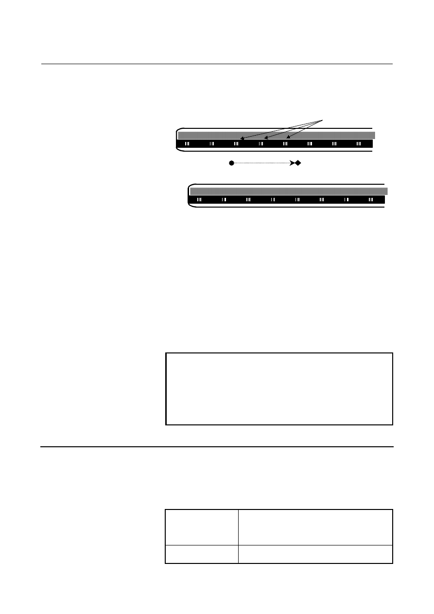
(4)  In this procedure, the axis does not stop until two, three or four 

reference marks are detected.    If this procedure is started at the 
position near the scale end, CNC can not detect three or four 
reference marks and the axis does not stop until over travel alarm 
occurs. Please care to start at the position that has enough 
distance from scale end. 


Scale end


Reference marks

Start point (Bad) 

Start point (Good)


(5)  When the axis used this function, the following function can not 

be used. 


Absolute position detection (absolute pulse coder) 


Three-dimensional error correction 

(6)  If axial movement is made in the direction opposite to that of 

reference position return, the movement is reversed to the 
direction of reference position return after three or four reference 
marks have been detected. Steps (3) to (5) of the basic procedure 
for establishing a reference position are carried out to establish 
the reference position. 

(7)  Straightness compensation function 
 

When the reference point establishment of moving axis is 
executed after the establishment of compensation axis, the 
compensation axis is moved by straightness compensation 
amount when the reference point of moving axis is established. 

(8)  The reference point establishment is not performed during 

synchronous control is activated. 

(9)  The reference point establishment is not performed during 

composite control is activated. 

(10) The reference point establishment is not performed during 

superimposed control is activated. 

B-63944EN/03

 OPERATION 

3.MANUAL OPERATION


- 1087 - 

3.11 

LINEAR SCALE WITH DISTANCE-CODED REFERENCE 
MARKS (SERIAL) 


Overview 

By using High-resolution serial output circuit for the linear scale with 
distance-coded reference marks (serial), the CNC measures the 
interval of referenced mark by axis moving of short distance and 
determines the absolute position. 
This function enables high-speed high-precision detection by using 
High-resolution serial output circuit. 
It is available that using maximum stroke 30 meters length. 
 

Explanation 

The linear scale with distance-coded reference marks (serial) is 
combined the irregular reference marked linear scale with the 
High-resolution serial output circuit, it can detect the accurate 
position. 

Reference mark signal 

10.02

10.04

10.06 

20

40

60 

0


The CNC measures the interval of referenced mark by axis moving of 
short distance and determines the absolute position, because of the 
interval of each reference mark is different with regular interval. 
It is not necessary that the axis is moved to the reference position for 
establishment of reference position. 
 
This function enables high-speed high-precision detection by using 
High-resolution serial output circuit. 
It is available that using maximum stroke 30 meters length. 
 

3.MANUAL OPERATION

 OPERATION 

B-63944EN/03


- 1088 - 

 - Connection 

It is available under linear motor system and full closed system. 


CNC 

Servo 

Amp 

Separate 

Detector 

Interface 

Unit 

Table 

High 

Resolution 

Serial Output 

Circuit C 

Full Closed System 

Linear scale with distance-coded 
reference marks (serial) 

Max. 30m 

Linear motor system

CNC 

Servo 

 Amp 

Linear motor 

Linear Motor 

Position Detection 

Circuit C 

Pole sensor

Linear scale with distance-coded 
reference marks (serial) 

Max. 30m 


B-63944EN/03

 OPERATION 

3.MANUAL OPERATION


- 1089 - 

  - Procedure for reference position establishment through manual operation 

(1)  Select the JOG mode, and set the manual reference position 

return selection signal ZRN to "1".   

(2)  Set a direction selection signal(+J1,-J1,+J2,-J2,…) for a target 

axis. 

(3)  The axis is fed at a constant low speed (reference position return 

FL feedrate specified by parameter No.1425 setting). 

(4)  When the absolute position of linear scale with distance-coded 

reference marks (serial) is detected, the axis stops. Then the 
absolute position of CNC is calculated and reference position 
establishment signal (ZRF1,ZRF2,ZRF3,…) turns to "1".   

 
The timing chart for this procedures is given below. 

FL rate 

JOG 

ZRN 

+J1 

Reference mark 

ZRF1

Feedrate 


  - Procedure for reference position establishment through automatic operation 

If an automatic reference position return (G28) is specified before a 
reference position is not established, steps (3) to (4) above are 
performed automatically. 
After the reference position is established, the automatic reference 
position return is performed by setting of parameter RFS No.1818#0. 
 

  - Stopping the operation for establishing a reference position 

The operation for establishing a reference position is stopped if any of 
the following operations is performed in steps (3) to (4), described 
above. 

 Reset 


Setting the feed axis direction selection signal (+J1, -J1, +J2, -J2, 
etc.) to 0 


Setting the Servo off signals (SVF1, SVF2, etc.) to 1 

If any of the following operations is performed during the operation of 
automatic reference position return (G28) before a reference position 
is not established, the operation for establishing a reference position 
stops: 

 Reset 

  Performing feed hold during movement from an intermediate 

position 


Setting the Servo off signals (SVF1, SVF2, etc.) to 1 

If the operation for establishing a reference position is stopped by an 
operation other than a reset, the operation for establishing a reference 
position must be reset and resumed. 
 

3.MANUAL OPERATION

 OPERATION 

B-63944EN/03


- 1090 - 

  - Establishing a reference position and moving to the reference position 

By following operation, establishing a reference position and moving 
to the reference position is performed. 


Moving through manual 

operation in REF mode 

Moving through automatic operation by 

automatic reference position return (G28) 

The reference 
position is not 
established. 

Establishing the reference 
position 

Firstly, moving to the intermediate position, and 
establishing the reference position. 
Secondly, whether moving to the reference 
position or not is performed by setting bit 0 
(RFS) of parameter No.1818. 

The reference 
position is 
established. 

Moving to the reference 
position 

Whether moving to the intermediate position and 
the reference position or not is performed by 
setting bit 1 (RF2) of parameter No.1818. 


  - Feed axis synchronization control 

In case of using the axis synchronization control, please confirm the 
following items. 

  When this function is used with axis synchronization control 

axes, the linear scale with distance-coded reference marks (serial) 
used for the master axis and that used for the slave axis must 
have reference marks placed at identical intervals. 


The master axis scale and the slave axis scale should be installed 
in parallel direction. (The zero positions should be faced the 
same direction.) 


To the parameters, which relate to this function (except No.1883, 
No.1884), the same value must be set for the master axis and for 
the slave axis. 

  The linear scale with distance-coded reference marks (serial) 

should be applied for the master axis and the slave axis. 
If either of the master axis or the slave axis is not the linear scale 
with distance-coded reference marks (serial), alarm DS0018 
occurs when reference position establishment is tried. 

  During operating the establishment of reference position, the 

state of signal for selecting synchronized axis(SYNCn<Gn138> 
or SYNCJn<Gn140>) should be kept. 

 
Procedure for reference position establishment by axis 

synchronization control is as follows. 


Both of axes (master axis and slave axis) are fed on the reference 
position return FL feedrate until distance coded scales of both 
axes detect the absolute position.   


Then absolute position of both axes are calculated and Reference 
Position Establishment Signals (ZRF1,ZRF2,...) turn to "1". 


B-63944EN/03

 OPERATION 

3.MANUAL OPERATION


- 1091 - 

  - Angular axis control 

In case of using the angular axis  control, please confirm the 
following items. 

  It is necessary to use the linear scale with distance-coded 

reference marks (serial)    for both the perpendicular axis and the 
angular axis. 
If not, the alarm DS0019 occurs when reference position 
establishment is commanded. 

  When the reference point establishment of angular and 

perpendicular axes are tried, please set bit 2 (AZR) of parameter 
No. 8200 to '0' and input signal NOZAGC <G063.5> to '0'. 
If not, the alarm DS0019 occurs when reference position 
establishment is commanded. 


When the reference point of the perpendicular axis is established, 
it is necessary to establish the reference point of the angular axis 
previously. When the reference point of the angular axis is not 
previously established, the alarm DS0020 occurs. 

  On angular axis control, if you use automatic setting of 

parameter No.1883,1884 on reference point establishment (bit 2 
(DATx) of parameter No.1819 = 1), please establish reference 
point of perpendicular axis after reference point establishment 
and return of angular axis. 

 
In manual reference position return, the perpendicular axis cannot be 
specified while the angular axis reference point is being established.   
The perpendicular axis, if specified, is ignored. 


Content      ..     139      140      141      142     ..