FANUC Series 30i/300i/300is-MODEL A. Machining Center System. User's manual - page 114
 

  Index      Manuals     FANUC Series 30i/300i/300is-MODEL A. Machining Center System. User's manual (B-63944EN/03)


Search            copyright infringement  


Content      ..     112      113      114      115     ..


FANUC Series 30i/300i/300is-MODEL A. Machining Center System. User's manual - page 114


22.5-AXIS MACHINING FUNCTION

 PROGRAMMING 

B-63944EN/03


- 868 - 

 - Multiple G68.3 

After the tool axis direction is changed in G68.3 mode, by specifying 
G68.3, a new feature coordinate system where the tool axis direction 
is the +Z-axis direction can be specified. 
 

    Example of operation 

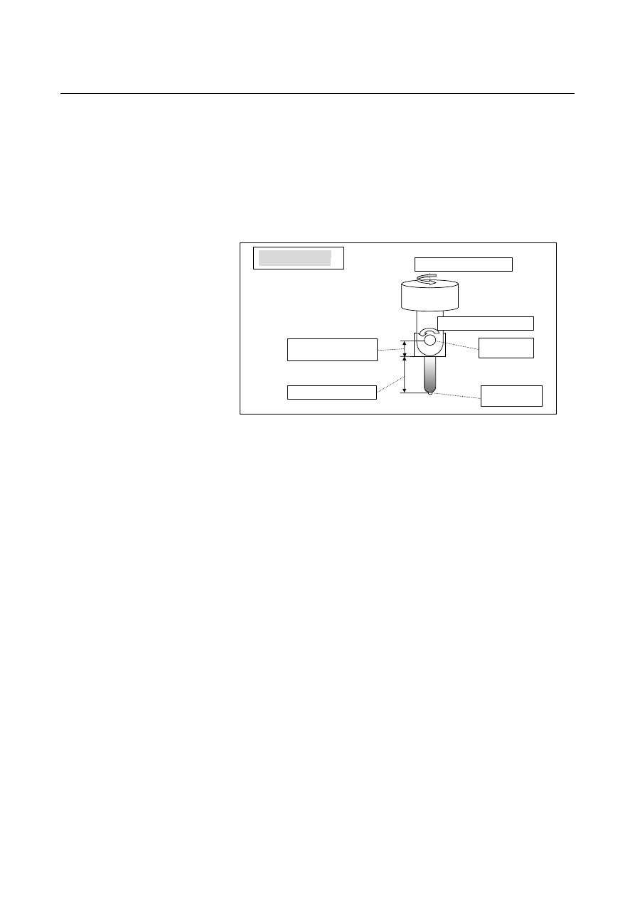
An example of operation on a machine of tool rotation type is given 
below. 
The machine configuration is "AC type reference tool axis Z-axis". 


A:  2nd rotation axis (slave)

C:    1st rotation axis (master)


Control point 

Tool holder offset value 
  = Parameter No. 19666 

Tool length offset = H01


AC type tool axis Z-axis


(Axes are intersecting.) 

Tool center point


Sample program 2 

O0200 ; 
N1 G55 ; 
N2 G01 A90.0 F1000 ; 
N3 G68.3 X0 Y0 Z0 R0; 

N4 X10.0 Y0 Z0 ; 
N5 C90.0; 
N6 G68.3 X10.0 Y0 Z0 ; 

N7 G69 ; 


B-63944EN/03

 PROGRAMMING 

22.5-AXIS MACHINING FUNCTION


- 869 - 


N3 command

N4 command

N6 command

N5 command

X

Machine operation by sample program 2 

Xc

Yc 

Zc

Xc 

Yc 

Zc 

Feature coordinate system Xc-Yc-Zc

X

Xc

Yc 

Zc 

X

Xc

Yc

Zc

X


N3 block: Sets a feature coordinate system according to the tool 

direction. 

N4 block:  Specifies coordinates in the feature coordinate system. 
N5 block:  Changes the tool direction. 
N6 block: Sets a feature coordinate system according to the tool 

direction. 


22.5-AXIS MACHINING FUNCTION

 PROGRAMMING 

B-63944EN/03


- 870 - 

22.3.3 

Tilted Working Plane command with Guidance 


Overview 

With the conventional tilted working plane command, a tilted working 
plane can be specified based on Eulerian angle and tool axis direction. 
This function enables a tilted working plane to be specified based on 
the following methods: 


Tilted working plane command based on roll-pitch-yaw 


Tilted working plane command based on three points 


Tilted working plane command based on two vectors 


Tilted working plane command based on projection angles 

The user can select most suitable commands for various types of 
machining. 
 
With the guidance screen function, a tilted working plane command 
block can be created by entering tilted working plane data on the 
screen.  A complicate tilted working plane command block can be 
created easily. 
 
The guidance screen function can be enabled by setting bit 1 (GGD) 
of parameter No. 11304 to 1. 
 
The tilted working plane command with guidance is an optional 
function. 


B-63944EN/03

 PROGRAMMING 

22.5-AXIS MACHINING FUNCTION


- 871 - 

22.3.3.1 

Tilted working plane command based on roll-pitch-yaw 


Overview 

With the tilted working plane command, coordinate system conversion 
by rotation about the X-axis, Y-axis, and Z-axis of a workpiece 
coordinate system in this order can be used (roll-pitch-yaw). 
The order of rotary axes can be specified using address Q. 

Xc 

Zc 

Yc 

(1) 

(2) 

(3) 


22.5-AXIS MACHINING FUNCTION

 PROGRAMMING 

B-63944EN/03


- 872 - 

Format 

Format


G68.2 P1 Qq X_ Y_ Z_ I

α

 J

β

 K

γ

Tilted working plane command


G69 ; 

Cancel tilted working plane command (M series). 

G69.1; 

Cancel tilted working plane command (T series).


Explanation of symbols 

: Order in which axes are rotated 

X_ Y_ Z_ : Origin of a feature coordinate system 

: Angle of rotation about the X-axis (roll angle) 

: Angle of rotation about the Y-axis (pitch angle) 

: Angle of rotation about the Z-axis (yaw angle) 

 
The values of address Q and the order in which axes are rotated are 
shown below.   


First rotation 

axis 

Second rotation 

axis 

Third rotation 

axis 

Q 123 

X axis 

Y axis 

Z axis 

Q 132 

X axis 

Z axis 

Y axis 

Q 213 

Y axis 

X axis 

Z axis 

Q 231 

Y axis 

Z axis 

X axis 

Q 312 

Z axis 

X axis 

Y axis 

Q 321 

Z axis 

Y axis 

X axis 


 CAUTION 

1  When address Q is omitted, the X-axis, Y-axis, and 

Z-axis are rotated in this order. 
(equivalent to Q123) 

2  When address Q is set to a value other than the 

above, alarm PS5457 is issued. 


Explanation 

Suppose that the coordinate system is rotated about (1) the X-axis, (2) 
the Y-axis, and (3) the Z-axis in this order. 
A "workpiece coordinate system" rotated by angle 

α

 about the X-axis 

is "coordinate system 1". 
"Coordinate system 1" rotated by angle 

β

 about the Y-axis is 

"coordinate system 2".  "Coordinate system 2" rotated by angle 

γ


about the Z-axis then shifted by (X

0

,Y

0

,Z

0

) from the workpiece 

coordinate system origin is a "feature coordinate system". 
 

B-63944EN/03

 PROGRAMMING 

22.5-AXIS MACHINING FUNCTION


- 873 - 


Conversion from the workpiece 
coordinate system X-Y-Z to 
coordinate system 1 X’-Y’-Z’ 

x

z

y

y’

z’

α

α

x

z

y

y’

z’

x’’

z’’

y’’

β

β

β

γ

x

z

y

x’’

z’’

y’’

γ

γ

xc

yc

zc

Conversion from coordinate system
1 X’-Y’-Z’ to coordinate system 2 
X"-Y"-Z" 

Conversion from coordinate system 2 
X"-Y"-Z" to the feature coordinate 
system Xc-Yc-Zc 


22.5-AXIS MACHINING FUNCTION

 PROGRAMMING 

B-63944EN/03


- 874 - 

G68.2 P1 Q123 X200.0 Y0 Z50.0 I30.0 J0 K90.0 ; 
G53.1 ; 
    : 

Example 

The example of a program when feature coordinate system like the 
figure below is used is shown below. 


Feature coordinate system origin  :  (200.0, 0, 50.0) 


Order in which axes are rotated 

:  X axis 

 Y axis 

 Z axis 


Angle of rotation about the X-axis :  30 degrees 


Angle of rotation about the Y-axis :  0 degree 


Angle of rotation about the Z-axis  :  90 degrees 

 
Example of a program 


X

Z

30

°

Xc 

Zc 

Yc

Workpiece coordinate system X-Y-Z 

Feature coordinate system

Xc-Yc-Zc 

200.0

50.0

B-63944EN/03

 PROGRAMMING 

22.5-AXIS MACHINING FUNCTION


- 875 - 

22.3.3.2 

Tilted working plane command based on three points 


Overview 

With the tilted working plane command, a tilted working plane can be 
specified by specifying three points in a feature coordinate system. 


X

Y

Z

P3 

P2 

P1

Xc

Zc

Yc


Format 


Format


G68.2 P2 Q0 X x

0

 Y y

0

 Z z

0   

R

α

 ; 

G68.2 P2 Q1 X x

1

 Y y

1

 Z z

1   

;  

G68.2 P2 Q2 X x

2

 Y y

2

 Z z

2   

;  

G68.2 P2 Q3 X x

3

 Y y

3

 Z z

3   

;  Tilted working plane command 

 
G69 ;  Cancel tilted working plane command (M series). 
G69.1;  Cancel tilted working plane command (T series). 

Explanation of symbols 

Q0 X x

0

 Y y

0

 Z z

0

 : Amount of shift from the first point to the origin of a 

feature coordinate system 


  By default, this value is 0. 

Q1 X x

1

 Y y

1

 Z z

1

  : First point. (origin of a feature coordinate system)

Q2 X x

2

 Y y

2

 Z z

2

 : Second point. 

Q3 X x

3

 Y y

3

 Z z

3

 : Third point. 

R  : Angle of rotation about the Z-axis of a feature coordinate system 
    By default, this value is 0. 
    Any block in the G68.2 P2 command can be specified.   


Content      ..     112      113      114      115     ..