FANUC Series 30i/300i/300is-MODEL A. Machining Center System. User's manual - page 112
 

  Index      Manuals     FANUC Series 30i/300i/300is-MODEL A. Machining Center System. User's manual (B-63944EN/03)


Search            copyright infringement  


Content      ..     110      111      112      113     ..


FANUC Series 30i/300i/300is-MODEL A. Machining Center System. User's manual - page 112


22.5-AXIS MACHINING FUNCTION

 PROGRAMMING 

B-63944EN/03


- 852 - 

  - Composite type machine 
 Basic 

operation 

This function is also available for a composite type machine in which 
the tool head rotates on the tool rotation axis and the table rotates on 
the table rotation axis. 
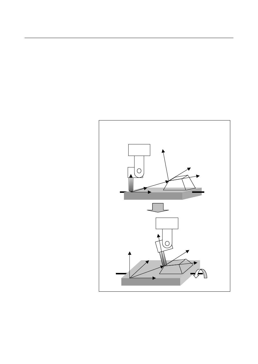
The feature coordinate system Xc-Yc-Zc is set in the workpiece 
coordinate system based on the coordinate system origin shift (xo, yo, 
zo) and the Euler's angle. 
Given the A-axis and B-axis shown in Fig. 22.3 (j), control is 
performed in such a way that the A-axis rotates until Zc comes in the 
X-Z plane and the B-axis is controlled so that the tool axis is oriented 
toward the +Z-axis direction of the feature coordinate system. 


X

Y

Z

A


X

Y

Z

A

(xo, yo, zo)

Xc


Yc


Zc

Xc'


Yc'


Zc'

    Tool axis direction control for a composite type machine 

B


Fig. 22.3 (j)    Composite type machine 


B-63944EN/03

 PROGRAMMING 

22.5-AXIS MACHINING FUNCTION


- 853 - 

  - Feature coordinate system with the table rotated by G53.1 (tool axis direction 

control) 

The composite type machine shown in Fig. 22.3 (j) is explained as an 
example. 
If the table rotates by the tool axis direction control command (G53.1), 
the feature coordinate system (called the first feature coordinate 
system), which is set in the workpiece coordinate system by the tilted 
working plane command (G68.2), rotates as much as the table rotates. 
The feature coordinate system that has rotated is called the second 
feature coordinate system. 
Once G53.1 is specified, the subsequent machining commands are 
assumed to be specified in the second feature coordinate system.  
(See Fig. 22.3 (k).) 
In the composite type machine, the specified feature coordinate 
system (the first feature coordinate system) may differ from the 
feature coordinate system to be used for machining (the second feature 
coordinate system). 

X

Y

Z

Xc'

Yc'

Zc'

  G53.1 command

X

Y

Z

Xc'

Yc'

Zc'

G01 Y10.0 F1000

command after G53.1

Second feature coordinate

system

Xc'-Yc'-Zc'

Second feature coordinate

system

Xc'-Yc'-Zc'


Fig. 22.3 (k)    Resetting of the feature coordinate system 

22.5-AXIS MACHINING FUNCTION

 PROGRAMMING 

B-63944EN/03


- 854 - 

  - Rotation direction of the table rotation axis 

The composite type machine shown in Fig. 22.3 (j) is explained as an 
example. 
Set parameter No.19684 to 1 if the rotation direction of the rotation 
table corresponding to the positive-direction move command is 
clockwise when viewed from the positive direction of the rotation 
center axis on which the table rotation axis rotates.  If the rotation 
direction is counterclockwise, set parameter No.19684 to 0. 
Let's take sample program 4 of O400 as an example, where the 
movement of the table is specified by G53.1. 
If parameter No.19684 is set to 1, control is performed in such a way 
that the table is rotated to A-45.0. 
If parameter No.19684 is set to 0, control is performed in such a way 
that the table is rotated to A45.0. 
Example) 

O400 (Sample Program4) ; 
N1 G68.2 X100.0 Y100.0 Z0 I180.0 J45.0 K0 ; 
N2 G53.1 ; 
N3 . . . ; 


X


Y


A

Xc

Yc

Zc

Yc

Xc

Zc

CCW CW


Rotation to A-45.0 

CCW


Rotation to A45.0 

CCW


Yc

Xc

Zc

Positive rotation direction when 
parameter No.19684 = 0


Positive rotation direction when 
parameter No.19684


= 1


G53.1 command

G53.1 command


Fig. 22.3 (l)    Rotation direction of the table rotation axis 

B-63944EN/03

 PROGRAMMING 

22.5-AXIS MACHINING FUNCTION


- 855 - 

  - Table rotation type machine 
 Basic 

operation 

This function is also usable for a table rotation type machine with two 
table rotation axes. 
The feature coordinate system Xc-Yc-Zc is set in the workpiece 
coordinate system based on the coordinate system origin shift (xo, yo, 
zo) and the Euler's angle. 
Given the A-axis and C-axis shown in Fig. 22.3 (m), the A-axis and 
C-axis rotate until Zc comes in the X-Z plane and the tool axis is 
directed toward the +Z-axis direction of the feature coordinate system. 
 

A

C

Xc

Yc

Zc

Yc'

Xc'

    Tool axis direction control for a table rotation type machine

X

Y

Z

A

X

Y

Z

Zc'

C


Fig. 22.3 (m)    Table rotation type machine 


22.5-AXIS MACHINING FUNCTION

 PROGRAMMING 

B-63944EN/03


- 856 - 

  - Feature coordinate system with the table rotated by G53.1 (tool axis direction 

control) 

The table rotation type machine shown in Fig. 22.3 (m) is explained as 
an example. 
If the table rotates by the tool axis direction control command (G53.1), 
the feature coordinate system (called the first feature coordinate 
system), which is set in the workpiece coordinate system by the tilted 
working plane command (G68.2), rotates as much as the table rotates. 
The feature coordinate system that has rotated is called the second 
feature coordinate system. 
Once G53.1 is specified, the subsequent machining commands are 
assumed to be specified in the second feature coordinate system.  
(See Fig. 22.3 (n).) 
In the table rotation type machine, the specified feature coordinate 
system (the first feature coordinate system) may differ from the 
feature coordinate system to be used for machining (the second feature 
coordinate system). 
 

  G53.1 command

G01 X10.0 F1000

command after G53.1

Yc'

Xc'

X

Y

Z

Zc'

Yc'

Xc'

X

Y

Z

Zc'

Second feature coordinate

system

Xc'-Yc'-Zc'

Second feature coordinate

system

Xc'-Yc'-Zc'


Fig. 22.3 (n)    Resetting of the feature coordinate system 

B-63944EN/03

 PROGRAMMING 

22.5-AXIS MACHINING FUNCTION


- 857 - 

  - Angle of the rotary axis 

When tool axis direction control (G53.1) has been performed, more 
than two pairs of "computed angles" of the rotary axes usually exist. 
The "computed angle" is the candidate angle at which the rotary axis 
is to be controlled in the tool axis direction specified by G53.1. 
The "output angle" is determined from the "computed angle" based on 
the "output judgment conditions" described below. 
When the upper and lower limits of the movement range of rotary 
axes are specified by parameters No. 19741 to No. 19744 at this time, 
a calculated angle that makes the two axes fall within the movement 
range is selected.   

"Output judgment conditions" 

Tool rotation type or table rotation type machine 

<1>  The "output angles" are represented by the computed rotary axis angle 

pair whose master axis (first rotary axis) moving angle is smaller. 


 When the master axis moving angle is the same 


<2>  The "output angles" are represented by the computed rotary axis angle 

pair whose slave axis (second rotary axis) moving angle is smaller. 


 When the slave axis moving angle is the same 


<3>  The "output angles" are represented by the computed rotary axis angle 

pair whose master axis (first rotary axis) angle is nearer to 0 degree 
(multiple of 360 degrees). 


 When the master axis angle is equally near to 0 degree 


<4>  The "output angles" are represented by the computed rotary axis angle 

pair whose slave axis (second rotary axis) angle is nearer to 0 degree 
(multiple of 360 degrees). 

Composite type machine 

<1>  The "output angles" are represented by the computed rotary axis angle 

pair whose table (second rotary axis) moving angle is smaller. 


 When the table moving angle is the same 


<2>  The "output angles" are represented by the computed rotary axis angle 

pair whose tool (first rotary axis) moving angle is smaller. 


 When the tool moving angle is the same 


<3>  The "output angles" are represented by the computed rotary axis angle 

pair whose table (second rotary axis) angle is nearer to 0 degree (multiple 
of 360 degrees). 


 When the master axis angle is equally near to 0 degree 


<4>  The "output angles" are represented by the computed rotary axis angle 

pair whose tool (first rotary axis) angle is nearer to 0 degree (multiple of 
360 degrees). 


22.5-AXIS MACHINING FUNCTION

 PROGRAMMING 

B-63944EN/03


- 858 - 

The process of judging whether the moving angle is smaller or larger 
as the output judgement condition is called "movement judgement." 
 
The "movement judgement" process is explained below. 
When the "computed angle" is within the range between 0 and 360 
degrees, it is called the "basic computed angle." 
Usually, two pairs of "basic computed angles" exist. 
For example, assume that the machine has rotary axis A (master) and 
rotary axis B (slave) and that there are two pairs of basic computed 
angles as follows: 
(A 

θ

1 degree; B 

φ

1 degree) 

(A 

θ

2 degrees; B 

φ

2 degrees)   where 

θ


θ

2 and 

φ


φ

2. 

The "computed angle" is obtained from either of the following 
expressions:  "basic computed angle" + 360 degrees 

×

 N or "basic 

computed angle" - 360 degrees 

×

 N. 

The current position of rotary axis A (master) is PA, and that of rotary 
axis B (slave) is 0 degree. 
Based on the PA angle, the "movement judgement" process is done as 
follows. 
 

  Computed angle A

-360 

×

 (N + 1) degrees

θ

1 - 360 

×

 N

-360 

×

 N degrees

θ

2 - 360 

×

 N

θ

2 - 360 

×

 (N + 1)

θ

1 - 360 

×

 (N - 1)

(*1)

0 degree

360 degrees

θ

2 - 360

θ

1

θ

2

θ

1 + 360

(*2)

360 

×

 (N + 1) degrees

θ

1 + 360 

×

 N

360 

×

 N degrees

θ

2 + 360 

×

 N

θ

2 + 360 

×

 (N - 1)

θ

1 + 360 

×

 (N + 1)

(*3)


"Movement judgment" 


B-63944EN/03

 PROGRAMMING 

22.5-AXIS MACHINING FUNCTION


- 859 - 

 
When the PA angle is (*1): 
The output angle is:    (A 

θ

2 - 360 × (N + 1) degrees; B 

φ

2 degrees). 

Namely, 

θ

2 - 360 × (N + 1) degrees is adopted that is nearer to the 

computed angle of A, and 

φ

2, which is the same group as 

θ

2, is 

adopted as the computed angle of B. 
 
When the PA angle is (*2): 
The output angle is:    (A 

θ

1 degrees; B 

φ

1 degrees). 

Namely, 

θ

1 degrees is adopted that is nearer to the computed angle of 

A, and 

φ

1, which is the same group as 

θ

1, is adopted as the computed 

angle of B. 
 
When the PA angle is (*3): 
The output angle is:    (A 

θ

2 + 360 × N degrees; B 

φ

2 degrees). 

Namely, 

θ

2 + 360 × N degrees is adopted that is nearer to the 

computed angle of A, and 

φ

2, which is the same group as 

θ

2. is 

adopted as the computed angle of B. 
 
When the moving angle of rotary axis A (master) is the same, a 
"movement judgement" is made for rotary axis B (slave) according to 
the "output judgment conditions." 
If the "output angle" of rotary axis A is determined by the "movement 
judgement" for rotary axis A, the computed angle representing the 
"smaller moving angle" is adopted as the "output angle" of rotary axis 
B. 
Similarly, if the "output angle" of rotary axis B is determined by the 
"movement judgement" for rotary axis B, the computed angle 
representing the "smaller moving angle" is adopted as the "output 
angle" of rotary axis A. 
 

 CAUTION 

1  To use the rotary axis roll-over function, set 

parameter No. 1260 (amount of rotary axis 
movement per rotation) to 360 degrees. 

2  A stroke limit before movement is applied to the 

rotary axis subject to tool axis direction control. 

3  If the setting of the lower limit (parameters No. 

19742 and No. 19744) is greater than that of the 
upper limit (parameters No. 19741 and No. 19743), 
alarm PS5459 is issued. 

4  If there is no calculated angle that falls within the 

movement range because the movement range is 
too small, alarm PS5459 is issued. 

5  When the parameters that specify the upper limit 

and lower limit of the movement range are set to 0, 
no movement range is assumed to be specified.   


Content      ..     110      111      112      113     ..