FANUC Series 30i/300i/300is-MODEL A. Machining Center System. User's manual - page 115
 

  Index      Manuals     FANUC Series 30i/300i/300is-MODEL A. Machining Center System. User's manual (B-63944EN/03)


Search            copyright infringement  


Content      ..     113      114      115      116     ..


FANUC Series 30i/300i/300is-MODEL A. Machining Center System. User's manual - page 115


22.5-AXIS MACHINING FUNCTION

 PROGRAMMING 

B-63944EN/03


- 876 - 


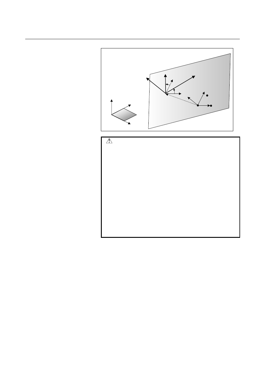
Coordinate system origin shift 

Xc 

Yc

Zc

Workpiece 
coordinate system 
X-Y-Z 

Feature coordinate system Xc-Yc-Zc

X

Y

Z

α

P1 

P3 

P2 


 CAUTION 

1  Three G68.2P2 commands (Q1, Q2, and Q3) 

determine a tilted plane.    If the G68.2P2 
commands are interrupted, alarm PS5457 is 
issued.  

2  When any of the following conditions is met or 

address Q is set to a value other than the above, 
alarm PS5457 is issued. 

  When two or more points are duplicate (the 

plane is not determined.) 

  When three points are placed on a line (the 

plane is not determined.) 

  When the distance between a line passing two 

of the three points and the remaining point is 
smaller than the setting of parameter No. 11220 
(the plane is unstable.) 


B-63944EN/03

 PROGRAMMING 

22.5-AXIS MACHINING FUNCTION


- 877 - 

Explanation 
  - Determination of a feature coordinate system 

Three entered points are named P1, P2, and P3 in the order of entry. 
The P1-to-P2 direction is defined as the X-axis of a feature coordinate 
system.  Among the directions that are on the plane containing the 
three points and are normal to the X-axis of the feature coordinate 
system, the direction that makes a smaller angle with the P1

P3 

vector is defined as the Y-axis of the feature coordinate system.    The 
Z-axis of the feature coordinate system is defined according to the 
right-handed system. 


Feature coordinate 
system 
Xc

Yc

Zc 

P1 

P3 

P2 

Xc 

Yc 
(Yc1) 

Zc 

Workpiece 
coordinate system 
X

Y

Z  

β


α


Yc2 

On the plane containing three points, there are two directions normal to 
Xc: Yc1 and Yc2.    Angles 

α

 and 

β

 formed relative to the P1

P3 vector 

satisfy 

α

β

, so that Yc1 is selected as Yc.


  - Origin of the feature coordinate system 

The origin of the feature coordinate system is the first specified point 
P1. 
By setting an origin shift amount (G68.2 P2 Q0 X_Y_Z_), the origin 
of the feature coordinate system is shifted by (X,Y,Z) from P1.  
Specify (X,Y,Z) in the feature coordinate system. 
 

  - Angular displacement R 

The angular displacement R is positive for clockwise rotation viewed 
in the Z-axis direction in the feature coordinate system. 
 

22.5-AXIS MACHINING FUNCTION

 PROGRAMMING 

B-63944EN/03


- 878 - 

G68.2 P2 Q1 X200.0 Y0 Z50.0 ; 
G68.2 P2 Q2 X200.0 Y100.0 Z50.0 ; 
G68.2 P2 Q3 X26.795 Y0 Z150.0 ; 
G53.1 ; 
  . . . 

Example 

The example of a program when feature coordinate system like the 
figure below is used is shown below. 


First point (origin of a feature coordinate system) 


:  (200.0, 0, 50.0) 


Second point  :  (200.0, 100.0, 50.0) 


Third point 

:  (26.795, 0, 150.0) 

 
Example of a program 


Z

30

°

Xc 

Zc 

Yc

Workpiece coordinate system X-Y-Z 

Feature coordinate system Xc-Yc-Zc

200.0

50.0

First point 

Second point

Third point

B-63944EN/03

 PROGRAMMING 

22.5-AXIS MACHINING FUNCTION


- 879 - 

22.3.3.3 

Tilted working plane command based on two vectors 


Overview 

With the tilted working plane command, a tilted working plane can be 
specified by specifying an X-axis direction vector and a Z-axis 
direction vector in the feature coordinate system. 


X

Y

Z

Xc

Zc

Yc

V1 

V2


Format 

Format 

G68.2 P3 Q1 X_ Y_ Z_ I

α

1

 J

β

1

 K

γ

G68.2 P3 Q2 I

α

2

 J

β

2

 K

γ

2


Tilted working plane command 

 
G69 ;  Cancel tilted working plane command (M series). 
G69.1;  Cancel tilted working plane command (T series). 

Explanation of symbols


X_ Y_ Z_ 

: Origin of a feature coordinate system (specifiable in 

the Q1 block) 

Q1 I

α

1

 J

β

1

 K

γ

1

  : Feature coordinate system X-axis direction relative to 

the workpiece coordinate system (first vector) 

Q2 I

α

2

 J

β

2

 K

γ

2

  : Feature coordinate system Z-axis direction relative to 

the workpiece coordinate system (second vector) 


 CAUTION 

1  The two G68.2P3 commands (Q1 and Q2) determine a tilted 

plane.    The G68.2P3 commands are interrupted, alarm 
PS5457 is issued. 

2  If the angle between the two vectors is 5 degrees or more off 

the 90 degrees, alarm PS5457 is issued.   

3  If (I, J, K) is set to a 0 vector, alarm PS5457 is issued.   


22.5-AXIS MACHINING FUNCTION

 PROGRAMMING 

B-63944EN/03


- 880 - 

Explanation 
  - Determination of a feature coordinate system 

The first vector is defined as the X-axis of the feature coordinate 
system, and the second vector is defined as the Z-axis of the feature 
coordinate system.  The Y-axis of the feature coordinate system is 
defined according to the right-handed system. 


Xc 

Zc

Yc (Yc1) 

V1

V2

Yc2

There are two vectors normal to the Xc-axis and Zc-axis.   
However, Yc1 is defined as the Yc-axis of the feature 
coordinate system according to the right-handed system. 


  - When the first and second vectors are not normal 

When the first vector and second vector are not normal, the 
orthographical vector from the second vector to plane P normal to the 
first vector is defined as the Z-axis of the feature coordinate system. 


Xc (first vector) 

Zc  

Second vector


Plane P normal to the first vector


B-63944EN/03

 PROGRAMMING 

22.5-AXIS MACHINING FUNCTION


- 881 - 

G68.2 P3 Q1 X200.0 Y0 Z50.0 I0 J1.0 K0 ; 
G68.2 P3 Q2 I100.0 J0 K173.205 ; 
G53.1 ; 
  . . . 

Example 

The example of a program when feature coordinate system like the 
figure below is used is shown below. 


Origin of a feature coordinate system 

:  (200.0, 0, 50.0) 

X-axis direction of a feature coordinate system  :  (0, 1.0, 0) 

(First vector) 


Z-axis direction of a feature coordinate system  :  (100.0, 0, 173.205) 

(Second vector )   

 
Example of a program 


X

Z

30

°

Xc 

Zc 

Yc

Workpiece coordinate system X-Y-Z 

Feature coordinate system

Xc-Yc-Zc 

200.0

50.0

First vector

Second vector

22.5-AXIS MACHINING FUNCTION

 PROGRAMMING 

B-63944EN/03


- 882 - 

22.3.3.4 

Tilted working plane command based on projection angles 


Overview 

With the tilted working plane command, a tilted working plane can be 
specified based on projection angles. 
A plane determined by vector A and vector B produced by rotating the 
X-axis vector and Y-axis vector of the workpiece coordinate system is 
defined to be a tilted working plane. 

X

Y

-

α


β

γ


Xc 

Yc

B


Format 


Format 

G68.2 P4 X_ Y_ Z_


I

α

 J

β

 K

γ

;  Tilted working plane command

 
G69 ;  Cancel tilted working plane command (M series). 
G69.1;  Cancel tilted working plane command (T series). 

Explanation of symbols 

X_ Y_ Z_ : Origin of a feature coordinate system 

α


: Angle by which the X-axis vector is rotated about the 

Y-axis of the workpiece coordinate system 

β


: Angle by which the Y-axis vector is rotated about the 

X-axis of the workpiece coordinate system 

γ


: Angle of rotation about the Z-axis of the feature coordinate 

system 


B-63944EN/03

 PROGRAMMING 

22.5-AXIS MACHINING FUNCTION


- 883 - 

Explanation 
  - Determination of a feature coordinate system 

The X-axis direction vector of the workpiece coordinate system 
rotated by 

α

 about the Y-axis of the workpiece coordinate system is 

defined as vector A.  The Y-axis direction vector of the workpiece 
coordinate system rotated by 

β

 about the X-axis of the workpiece 

coordinate system is defined to be vector B. 
The direction normal to plane P containing vector A and vector B 
(direction of the outer product of A 

×

 B) is defined to be the Z-axis 

direction of the feature coordinate system. 
Vector A rotated by 

γ

 about the Z-axis of the feature coordinate 

system is defined to be the X-axis direction of the feature coordinate 
system.  The Y-axis of the feature coordinate system is defined 
according to the right-handed system. 


X

Y

Z

-

α


β

A

B

Zc

Plane P


By the third command angle 

α

 and second command angle 

β

, the 

Z-axis of the feature coordinate system are determined. 


X

Y

Z

A

B

Yc

γ


Plane P

Zc

Xc 


Content      ..     113      114      115      116     ..