FANUC Series 30i/300i/300is-MODEL A. Machining Center System. User's manual - page 81
 

  Index      Manuals     FANUC Series 30i/300i/300is-MODEL A. Machining Center System. User's manual (B-63944EN/03)


Search            copyright infringement  


Content      ..     79      80      81      82     ..


FANUC Series 30i/300i/300is-MODEL A. Machining Center System. User's manual - page 81


17.REAL-TIME CUSTOM MACRO

 PROGRAMMING 

B-63944EN/03


- 604 - 

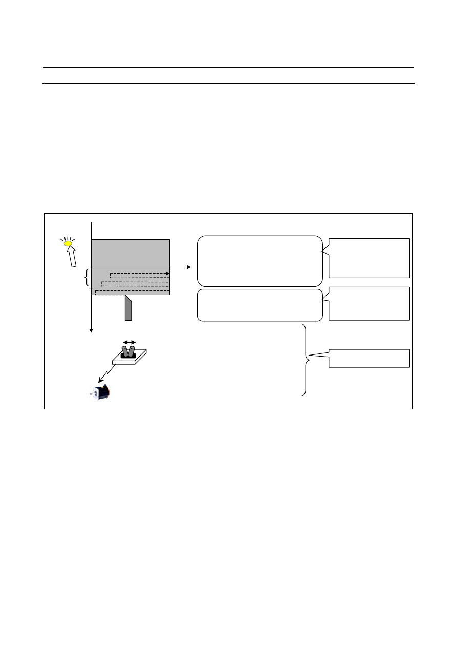
Sample program 

The sample program below exercises the following three control 
operations at the same time. 
(1)  A cutting operation is performed on the X-axis and Z-axis. 
(2)  On each rising edge of the X signal 5.2, 20 is fed on the 

peripheral axis A. 

(3)  When the workpiece coordinate on the X-axis (#100101) is equal 

to or less than 50, the Y signal 2.3 is set to 1. 

 
The operation of (1) is coded in the main NC statement. 
The operation of (2) is coded in the first modal RTM command (//1). 
The operation of (3) is coded in the second modal RTM command 
(//2). 


O0001 ; 
G90 G00 X100 Z100; 
 
//1 ZWHILE[1] ZDO ; 
ZEDGE [#IOX[5,2] EQ 1 ] ZDO ; 
G91 G00 A20. ; 
ZEND ; 
ZEND ; 
 
 
//2 ZWHILE[1] ZDO ; 
ZEDGE [ #100101 LE 50.0 ] #IOY[2,3] = 1 ; 
ZEND ; 
 
#100=100 ; 
WHILE [ #100 GT 0 ]) DO1 
G91 G01 Z-#100 F200. ; 
Z#100. ; 
#100 = #100 - 10 ; 
X-10. F100; 
END1 
M02 ; 

Workpiece 


                    50 
(Y signal is 
turned on 
when tool 
enters this 
range.)


Z

RTM command (2) 
operation 
(On each rising edge of 
X5.2, 20 is fed on peripheral
axis A.) 

RTM command (3) 
operation 
(When X coordinate is 50 or 
less, Y signal 2.3 is set to 1.)

Command for cutting on 
X-axis and Z-axis 

Peripheral axis A 

Signal switch 
(Address X5.2) 

Signal lamp 
(Address 
Y2.3) 


B-63944EN/03

 PROGRAMMING 

17.REAL-TIME CUSTOM MACRO


- 605 - 

17.5 

MACRO CALL 

 
A series of RTM statements can be formed into a subprogram, which 
can be called from the main program. 
 
When G65 is specified in an RTM command, the real time macro 
specified in address P is called. 


Explanation 
 - Calling 

In address P after G65, specify the program number of a real time 
custom macro to be called. 
 

NOTE 

1  In argument P of G65, only a constant value can 

be used.    No value can be specified through a 
variable.   

  Example:     
  // G65 P9010 ;      Correct      
  // G65 P#RV[0] ;    Incorrect 
2  The inclusion of another NC command (such as 

G01 X100.0 G65 Pp) is not allowed.    If another 
NC command is included, PS0127 alarm is issued. 

3  The G65 block for calling a real time macro does 

not make a single block stop. 

4  On the other hand, a real time macro program 

called by real time macro calling makes a single 
block stop. 


P  :  Number of real time macro program to be called

O0001 ; 
 : 
 : 
//1 G65 P9010 ; 
G04 P2000 ; 
 : 
 : 
M30 ; 

O9010 ; 
 : 
 : 
 : 
 : 
 : 
 : 
M99 ; 

G65


P p ; 

The execution of real time macro //1 including O9010 starts simultaneously 
with the G04 block of main program O0001. 

Code real time macro
statements. 

17.REAL-TIME CUSTOM MACRO

 PROGRAMMING 

B-63944EN/03


- 606 - 

  - Call destination real time program 

In a called real time macro program, only an RTM statement can be 
coded. 
 
In a called real time macro program, no additional RTM command 
may be executed.  (The RTM command symbol ‘//’ may not be 
coded.)    For example, do not execute the following program: 
 
O0001 ; 

O9010 ; 

// G65 P9010 ; 

// #RV[0]=1 ; 

M02 ; 

M99 ; 

 
Code M99 in the last block only. 
For example, do not execute the following program: 
 
O0001 ; 

O9010 ; 

// G65 P9010 ; 

ZEDGE [#RV[0] EQ 1] M99 ; 

M02 ; 

G91 G00 X50. ; 

 M99 

 
When executing an RTM statement in a subprogram, code an NC 
statement before the M99 block for returning to the calling program. 
 
O0001 ; 

O9010 ; 

G65 P9010 ; 

// #RV[0] = 20 ; Real time macro statement 

M02 ; 

G04 ;                  NC statement 

 M99 


 - Format 

Specify G65 at the start of a block. 
 

  - Call nesting level 

Macro call nesting is not allowed. 
 

  - Differences from macro call using a custom macro 

Macro call using a real time custom macro and macro call using a 
custom macro differs as described below. 


In macro call using a custom macro, an argument (data to be 
passed to a macro) and the number of repetitions can be specified.   
In macro call using a real time custom macro, such information 
cannot be specified. 


With a real time custom macro, other types of macro call (macro 
call using G66, G66.1, G, and M code) and subprogram call are 
not allowed. 


B-63944EN/03

 PROGRAMMING 

17.REAL-TIME CUSTOM MACRO


- 607 - 

17.6 

OTHERS 

 
If an axis control command is followed by a macro command in an 
RTM command, the execution of the macro command starts when the 
axis control command is completed or deceleration starts. 
If deceleration on the X-axis starts upon completion of distribution 
according to the axis control command of (1), for example, the macro 
command of (2) is executed.  If acceleration/deceleration is not 
applied on the X-axis, (2) is executed upon completion of distribution 
on the X-axis. 
// ZDO ; 
G91 G00 X30 ; 

(1) Axis control command of the RTM statement 

#RV[0] = 1 ; 

(2) Macro command of the RTM statement 

ZEND ; 
 
If an RTM command is executed in a custom macro WHILE DO to 
END loop, and the same RTM is looked ahead while the RTM 
command is being executed, a PS alarm may be issued. 
For example, if the command below is executed, a PS alarm is issued. 
 
WHILE [1] DO1 ; 
// #RV[0] = #RV[0] + 1 ; 
#100=#100+1 ; 
END1 ; 
 
In this example, insert G04 ; block between a #100=#100+1; and 
END1;. 
 

17.REAL-TIME CUSTOM MACRO

 PROGRAMMING 

B-63944EN/03


- 608 - 

17.7 

AXIS CONTROL COMMAND 

 
In an RTM statement, a G code for specifying a movement can be 
specified.  For axis control, the PMC axis control interface is used.   
The specifications differ from the specifications for the G code used 
with an NC statement. 
 

Format 

// ZDO ; 
G_ 

IP

 _ F_ ; 

    : 
ZEND ; 

 
For an axis control command, ZDO...ZEND of multi-statement 
structure is used for coding even if a single statement (single RTM 
statement) is used. 
 

 CAUTION 


Do not specify an NC statement for an axis to be 
controlled with an RTM statement.    Moreover, do 
not exercise axis control with an RTM statement on 
an axis to be controlled with an NC statement. 


NOTE 

1  In one block, only one axis may be specified.    Do 

not specify two or more axes in the same block. 

2  In the three-dimensional coordinate conversion 

mode, the polygon mode, etc., an RTM statement 
concerning that axis cannot be specified. 


Explanation 
 - Setting 

For an axis control command in an RTM statement, the interface of a 
PMC axis control group set by a parameter beforehand is used. 
For an axis to be controlled with an RTM statement, set a group to be 
used with parameter No. 8010.    Then, set bit 0 (XRT) of parameter 
No. 8011 for the axis to 1. 
 

NOTE 


An axis for which bit 0 (XRT) of parameter No. 
8011 is set to 1 is dedicated to real time custom 
macros, so that such an axis cannot be used with 
PMC axis control. 


B-63944EN/03

 PROGRAMMING 

17.REAL-TIME CUSTOM MACRO


- 609 - 

  - Relationship with PMC axis control 

Axis control based on an RTM statement uses the PMC axis control 
interface.    So, the specifications for a move command in each block 
within an RTM statement are generally equivalent to the specifications 
for the PMC axis control command. 
For the detailed specifications and restrictions related to axis control, 
refer to the specifications of PMC axis control as well. 
 

NOTE 

1  An axis used with an RTM statement must not be 

specified from PMC axis control. 

2  A PMC axis control group used with an RTM 

statement must not be specified from PMC axis 
control. 


  - Operation command code 

The table below indicates the G codes that can be specified in an RTM 
statement. 
The    mark in the table indicates modal G codes when an RTM 
command starts. 

Code Group 

Meaning 

G00 Positioning 
G01 

01 

Feed at specified feedrate 

G28 

Reference position return 

G53 

00 

Machine coordinate system selection 

G90 Absolute 

command 

NOTE 1


G91 

03 

Incremental command 

NOTE 2


G94 

Feed per minute 

G95 

05 

Feed per revolution 


NOTE 

1  The absolute command (G90) is valid for machine 

coordinate system selection (G53) only. 

2  The incremental command (G91) is valid for 

positioning (G00), linear interpolation (G01), and 
reference position return (G28) only. 

3  In T series G code system A as well, not G98/G99 

but G90/G91 are valid with an RTM command. 


 - Modal information 

Basically, modal information such as F and modal G codes in an RTM 
statement is independent in an NC statement and each RTM statement. 
Modal information in an RTM statement is initialized when the 
execution of the RTM statement is started (when a block specified 
with // is executed). 
The initial value of modal information in an RTM statement is as 
follows: 
 

State of the G codes marked with        in the operation command 
code list 

 F 

code 

F0 

17.REAL-TIME CUSTOM MACRO

 PROGRAMMING 

B-63944EN/03


- 610 - 


 CAUTION 


With the G codes (inch input/metric input) of group 
06, the same information as the modal information 
of an NC statement is used in an RTM statement.   
Do not change the modal information of group 06 
with an NC statement in a block after the first RTM 
statement coded in a program. 


NOTE 


With an RTM command, bit 0 (G01), bit 3 (G91), 
and bit 4 (FPM) of parameter No. 3402 are invalid 
when the power is turned on or in the cleared 
state. 


Example 1) 
 

Modal information can be controlled independently in an NC 
statement and each RTM statement. 

O0001 ; 


G90 G01 X100. Y100. F500. ; 

(1) 


//1 ZDO ; 


Z50. ; 

(2) 


G01 Z100. F100. ; 

(3) 


ZEND ; 


//2 ZDO ; 


G01 A30. F200. ; 

(4) 


A50. ; 

(5) 


ZEND ; 


X200. ; 

(6) 


:  


The modal information of command (2) is G00, G91, and G94, 
regardless of the modal information (G90 G01 set in (1)) of the 
NC statement. 


The modal information of command 

(5)

 is G01, G91, G94, and 

F200..  This modal information is not affected by the modal 
information (command (1)) of the NC statement and the modal 
information (commands (2) and

 (3)

) in the RTM statement with 

modal ID=1. 


The modal information of command 

(6)

 is not affected by the 

modal information (commands 

(2)

 to (5)) in the RTM statement, 

so that the modal information is G01, G90, and F500.. 


B-63944EN/03

 PROGRAMMING 

17.REAL-TIME CUSTOM MACRO


- 611 - 

Example 2) 
 

Modal information is initialized when the execution of each 
RTM command is started.    Even if the same program includes 
RTM commands with the same ID, the modal information of the 
RTM command executed first is not inherited by the RTM 
command executed next. 

O0001 ; 


G90 G01 X100. Y100. F500. ; 


//1 ZDO ; 


G01 Z100. F3000. ; 

(1) 


ZEND ; 


X200. ; 


//1 ZDO ; 


Z200. ; 

(2) 


ZEND ; 


X300. ; 


:  


The modal information of command (2) is G91 and G00, 
regardless of command 

(1)


  - Single block stop 

If an NC statement is placed in the single block stop state, for example, 
by the single block stop signal SBK, the axis control command of an 
RTM statement also comes to a single block stop. 
However, the automatic operation start signal STL is turned off when 
all conditions on the NC statement side are satisfied, even if the axis 
control command of an RTM statement is not terminated. 
If an RTM command consists of multiple statements and an axis 
control command is coded in multiple blocks, only the block of the 
RTM statement that is currently executing an axis command can be 
brought to a single block stop by setting the group-by-group single 
block stop signal (ESBKg) for PMC axis control corresponding to the 
axis to 1. 
 

 - Feed hold 

Even when an NC statement enters the automatic operation halt state, 
the axis control command of an RTM statement does not stop 
immediately but stops at the time of termination of the block currently 
being executed.    To stop also the axis control command of an RTM 
statement immediately when the NC statement enters the automatic 
operation halt state, control the temporary stop signal (ESTPg) for 
PMC axis control of the related group by monitoring the automatic 
operation halt in-progress signal (SPL). 


Content      ..     79      80      81      82     ..