FANUC Series 30i/300i/300is-MODEL A. Machining Center System. User's manual - page 79
 

  Index      Manuals     FANUC Series 30i/300i/300is-MODEL A. Machining Center System. User's manual (B-63944EN/03)


Search            copyright infringement  


Content      ..     77      78      79      80     ..


FANUC Series 30i/300i/300is-MODEL A. Machining Center System. User's manual - page 79


17.REAL-TIME CUSTOM MACRO

 PROGRAMMING 

B-63944EN/03


- 588 - 

17.2 

VARIABLES 


Overview 

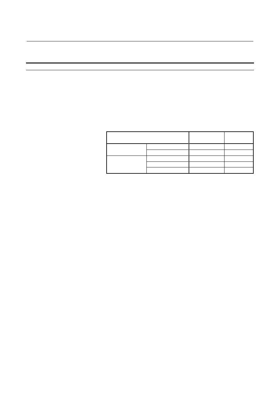
With real time custom macros, the following variables can be handled: 
 
- System variables dedicated to real time custom macros 
- Variables (RTM variables) dedicated to real time custom macros 
- System variables for some custom macros   
 
The RTM variables mean the variables dedicated to real time custom 
macros. 

List of usable variables 

 Real 

time 

custom macro 

Custom 

macro 

System variables 

Usable 

Unusable 

Real time custom 
macro variables 

RTM variables 

Usable 

Unusable 

System variables 

Partially usable 

Usable 

Common variables 

Unusable 

Usable 

Custom macro 
variables 

Local variables 

Unusable 

Usable 

 
The variables (system variables and RTM variables) dedicated to real 
time custom macros are the variables specific to the real time custom 
macro function.  Those variables cannot be used with the custom 
macro function. 
 

B-63944EN/03

 PROGRAMMING 

17.REAL-TIME CUSTOM MACRO


- 589 - 

17.2.1 

Variables Dedicated To Real Time Custom Macros 

 
These variables are dedicated to real time custom macros.  The 
variables are classified as system variables and RTM variables. 
 

17.2.1.1 

System variables 

 
System variables dedicated to real time custom macros 


Format 

#IOp [m, n]  Bit-by-bit read/write 
#IOpB [m]  Byte-by-byte read/write 
#IOpW [m]  Word-by-word read/write 
#IOpD [m]  Double word-by-double word read/write 

p :  Signal type (X, G, F, Y, D, R) 
m :  Signal byte address 
n :  (Used for bit-by-bit read/write only)    Signal address bit 

number (0 to 7) 

 
PMC interface signals are read and written.  Bit-by-bit and 
byte-by-byte read/write operations are possible. 
The following signals can be used: 

Variable name

Signal type 

Read 

Write 

#IOX 

#IOXB 

#IOXW 

#IOXD 

X Possible 

Impossible 

#IOG 

#IOGB 

#IOGW 

#IOGD 

G Impossible 

Possible 

#IOF 

#IOFB 

#IOFW 

#IOFD 

F Possible 

Impossible 

#IOY 

#IOYB 

#IOYW 

#IOYD 

Y Impossible 

Possible 

#IOD 

#IODB 

#IODW 

#IODD 

D Possible 

Possible 

#IOR 

#IORB 

#IORW 

#IORD 

R Possible 

Possible 

 
For the valid signal address range, see the specifications of the PMC 
as well. 
 
When writing to a signal, make the variable unprotected on the PMC 
signal protection screen (described later) beforehand. 
 

17.REAL-TIME CUSTOM MACRO

 PROGRAMMING 

B-63944EN/03


- 590 - 

Specify an address by using m and n. 
Example: 
 

#IOF[1, 3] 


F1.3 bit type 


#IOG[1, 5]   

G1.5 bit type 


#IOFB[32]   

F32 byte type 


#IOGB[12]   

G12 byte type 

 
Read/write operations are performed in the same as for an ordinary 
macro statement. 
Example: 
 

#RV[0]=#IOFB[32] 

Assigns F32 to #RV[0]. 


#IOG[99.3] = 1 


Sets G99.3 to 1. 

 
If a signal at a nonexistent address is specified, a PS alarm is issued. 
 

 CAUTION 

1  Controls handling other signals, such as a ladder 

or macro executor, must not write to a signal 
address being written to by an RTM statement.   
Ensure that a single control writes to the same byte 
signal address. 


For example, when the G000.0 signal is written to 
by an RTM statement, do not write to the G000.7 
signal from a ladder. 

2  Ensure that the same F signal is not read from by 

an RTM statement and written to by the NC 
simultaneously. 

3  Ensure that the same G signal is not written to by 

an RTM statement and read from by the NC 
simultaneously. 

4  For word-by-word read/write, specify an 

even-numbered address and for double 
word-by-double word read/write, specify an 
address that is a multiple of four. 


NOTE 


The system variables described above are not 
supported for a multi-path PMC. 


  - PMC signal protection 

Whether to enable a write to a signal handled by an RTM statement 
can be set.  This function protects against a malfunction due to 
incorrect coding. 
 
On the PMC signal protection screen, set whether to enable a write to 
a signal. 
If an RTM statement makes an attempt to write to a signal 
write-protected on the PMC signal protection screen, a PS alarm is 
issued at the time of execution. 
 

B-63944EN/03

 PROGRAMMING 

17.REAL-TIME CUSTOM MACRO


- 591 - 

Set whether to enable a write to each address of Y and G on a 
byte-by-byte basis. 
For each of addresses D and R, set a write-enabled range. 
 
For the unwritable signals (X, F), the screen is not displayed. 
 
Before changing an address on the PMC signal protection range 
specification screen, perform a clear operation first and then input a 
new address. 
 

 - Input/output 

A value set for PMC signal protection can be input/output. 
 

 - Input/output format 

After punching PMC signal protection, one file(DIDOENBL.TXT) is 
created. 
Please execute input/output operation in EDIT mode. 
The output format is as follows: 
L Specification 

method 


0: Byte specification 


1: Range specification 

Q  Alphabetic signal address 
 

0: G, 2: Y, 5: R, 9: D 

K  (for use in range specification only) Index number (0 to 9) 

Address number for byte specification 


Start address number for range specification 

Protection value for byte specification 


0: Not writable 

 1: 

Writable 


End address number 


for range specification 

 
Example of output 


L0Q2R0000P0 
L0Q2R0001P1 

L0Q2R0127P1 

L0Q0R0000P1 
L0Q0R0001P1 

L0Q0R0767P0 
L0Q0R1000P1 

L0Q0R1767P0 

L1Q5K0R0002P0014 

L1Q9K9R0032P0127 
M02 


Byte 
specification 

G0 to G767 protect 
information 

G1000 to G1767 protect 
information 

Y0 to Y127 protect 
information 

R2 to R14 are writable 
(Index 0) 
D32 to D127 are writable 
(Index 9) 

Range 
specification 

17.REAL-TIME CUSTOM MACRO

 PROGRAMMING 

B-63944EN/03


- 592 - 

17.2.1.2 

Real time macro variables    (RTM variables) 

 
The real time macro variables (RTM variables) are variables dedicated 
to real time custom macros. 
The RTM variables are classified as volatile real time macro variables 
(volatile RTM variables) and nonvolatile real time macro variables 
(nonvolatile RTM variables). 
 
The data of a nonvolatile RTM variable is preserved even when the 
power is turned off. 
The data of a volatile RTM variable is cleared to 0 when the power is 
turned off. 


Format 

#RV [ m ]      Volatile RTM variable 

m:  Volatile RTM variable number (0 to 99) 

#RVS [ n ]    Nonvolatile RTM variable 

n:  Nonvolatile RTM variable number (0 to 31) 


NOTE 

1  RTM variables can be used with an RTM statement 

only. RTM variables cannot be used with an NC 
statement and macro statement. 

2  No RTM variable assumes a "null" value. 
3  Volatile RTM variables are cleared to 0 by a reset. 

On the other hand, nonvolatile RTM variables are 
not cleared to 0 by a reset. 


Explanation 
 - Input/output 

RTM variables can be input/output in a specified format. 
Both nonvolatile RTM variables and volatile RTM variables can be 
input/output. 
 

 - Input/output format 

After punching RTM variables, one file(RTMMACRO.TXT) is 
created. 
The output format is described below. 
The value of an RTM variable is output in hexadecimal as a 
double-precision floating-point data bit image. 
When a nonvolatile RTM variable is output, G10L87 is followed by 
an RTM variable number and a variable value. 
When a volatile RTM variable is output, G10L88 is followed by an 
RTM variable number and a variable value. 
 

B-63944EN/03

 PROGRAMMING 

17.REAL-TIME CUSTOM MACRO


- 593 - 

Example of output 


G10L87P0(3FE0000000000000) 
G10L87P1(4000000000000000) 

G10L87P30(4010000000000000) 
G10L87P31(4014000000000000) 
 
G10L88P0(4008000000000000) 
G10L88P1(3FD9999999800000) 

G10L88P98(3FF0000000000000) 
G10L88P99(4010000000000000) 
M02 


Execute input/output operation in EDIT mode. 


Nonvolatile RTM variable 

Volatile RTM variable 

17.REAL-TIME CUSTOM MACRO

 PROGRAMMING 

B-63944EN/03


- 594 - 

17.2.2 

Custom Macro Variables 

 
With real time custom macros, a part of the custom macro variables 
(part of the system variables) can be handled. 
 

17.2.2.1 

System variables 

 
With real time custom macros, position-related information among the 
system variables of the custom macros can be handled. 
 

  - Position information #100001 to #100182 (Attribute:    Read only) 
 

Block 

end 

position 

    #100001 

to 

#100032 

  Current position (machine coordinate system) 

#100051 to #100082 

  Current position (workpiece coordinate system)  #100101 to #100132 
 

Skip 

position    

  #100151 

to 

#100182 

By readying the values of system variables #100001 to #100182, the 
end position of the previous block, the current positions (machine 
coordinate system and workpiece coordinate system), and skip signal 
position can be found. 
 

Variable No.

Position information 

Coordinate system 

#100001 
#100002 

#100032 

Block end position on 1st axis 
Block end position on 2nd axis 
                      : 
Block end position on 32nd axis 

Workpiece coordinate 
system 

#100051 
#100052 

#100082 

Current position on 1st axis 
Current position on 2nd axis 
                      : 
Current position on 32nd axis 

Machine coordinate 
system 

#100101 
#100102 

#100132 

Current position on 1st axis 
Current position on 2nd axis 
                      : 
Current position on 32nd axis 

Workpiece coordinate 
system 

#100151 
#100152 

#100182 

Skip position on 1st axis 
Skip position on 2nd axis 
                      : 
Skip position on 32nd axis 

Workpiece coordinate 
system 


NOTE 

1  The value of a variable with a number greater than 

the number of controlled axes is undefined. 

2  The end position (ABSIO) of a skip (G31) block is 

the skip signal ON position if the skip signal is 
turned on.    If the skip signal is not turned on, the 
block end point is undefined. 

3  As block end position information #100001 to 

#100032, the end positions read in advance are 
obtained instead of the end positions of the block 
currently being executed. 


B-63944EN/03

 PROGRAMMING 

17.REAL-TIME CUSTOM MACRO


- 595 - 

  - Servo positional deviation #100251 to #100282 (Attribute:    Read only) 

By reading the values of system variables #100251 to #100282, the 
servo positional deviation on each axis can be found. 
 

Variable No. 

Position information 

#100251 
#100252 

#100282 

Servo positional deviation on 1st axis 
Servo positional deviation on 2nd axis 
                      : 
Servo positional deviation on 32nd axis 


NOTE 


The value of a variable with a number greater than 
the number of controlled axes is undefined. 


  - Remaining travel distance #100801 to #100832 (Attribute:    Read only) 

By reading the values of system variables #100801 to #100832, the 
remaining travel distance on each axis can be read. 
 

Variable No. 

Position information 

#100801 
#100802 

#100832 

Travel distance on 1st axis 
Travel distance on 2nd axis 
                      : 
Travel distance on 32nd axis 


NOTE 

1  The value of a variable with a number greater than 

the number of controlled axes is undefined. 

2  System variables not described here are unusable. 
3  The name of a system variable cannot be 

specified. 
Do not specify a command as indicated below. 
    //1 #RV[0]=[#_ABSOT[1]] ; 


17.2.2.2 

Local variables 

 
The local variables(#1 to #33) cannot be used. 


Content      ..     77      78      79      80     ..