FANUC Robot M-710iC MECHANICAL UNIT. OPERATOR'S MANUAL (B-82274EN/09) - page 3
3.BASIC SPECIFICATIONS
B-82274EN/09
108
(deg)
72(deg)
J5-axis rotation center
Motion range of
J5-axis roation center
-108(deg)
-72(deg)
J5-axis rotation center
Range of motion when J1=±90(deg)
Range of motion when
-180(deg)≦J1≦-108(deg)
-72(deg)≦J1≦
72(deg)
108(deg)≦J1≦ 180(deg)
Motion range of
J5-axis rotation center
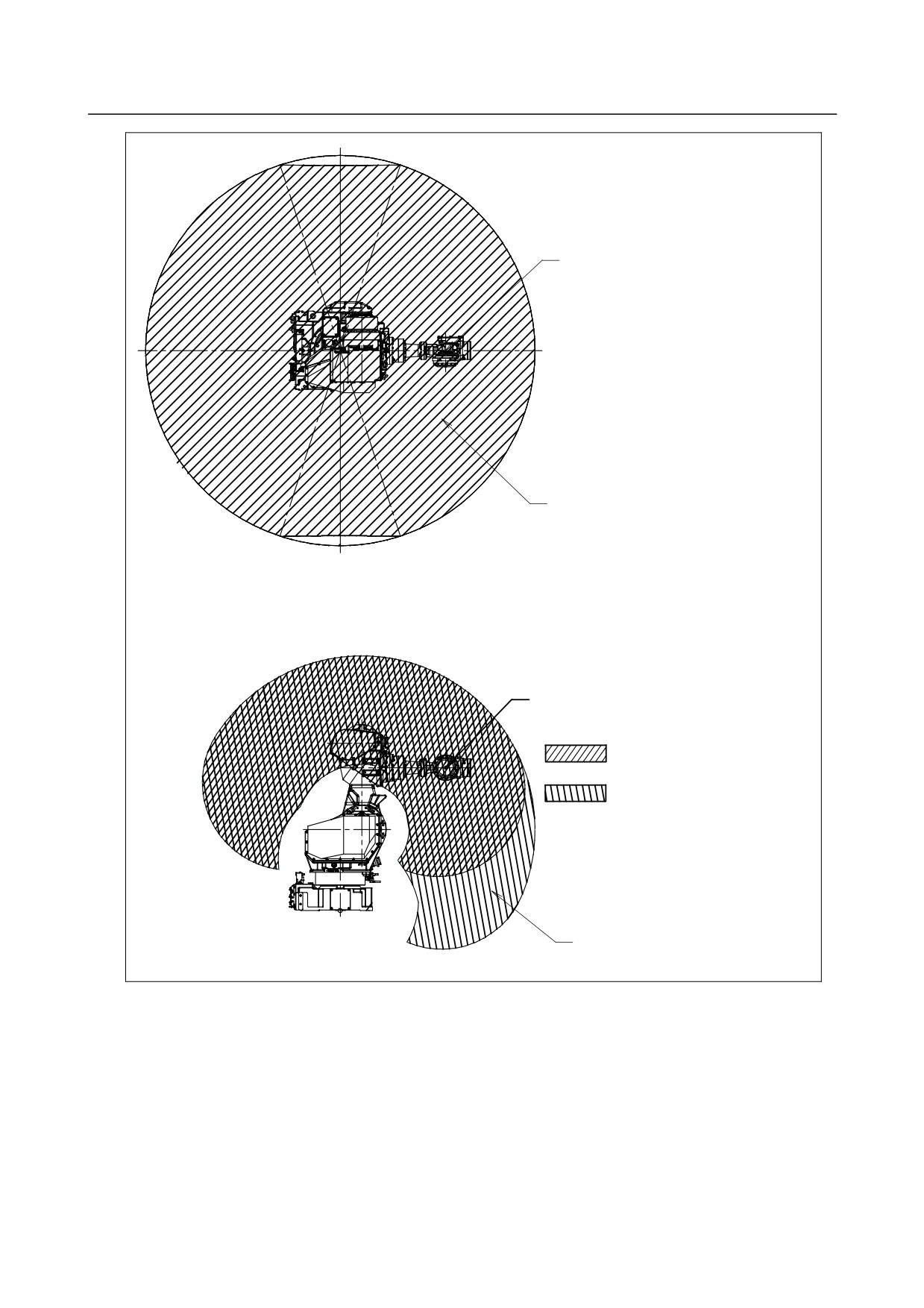
Fig.3.6 (l) Motion range for mounted angle range (2) (M-710iC/50S)
- 40 -
B-82274EN/09
4.MECHANICAL COUPLING TO THE ROBOT
4 MECHANICAL COUPLING TO THE ROBOT
4.1
MECHANICAL COUPLING OF END EFFECTOR TO WRIST
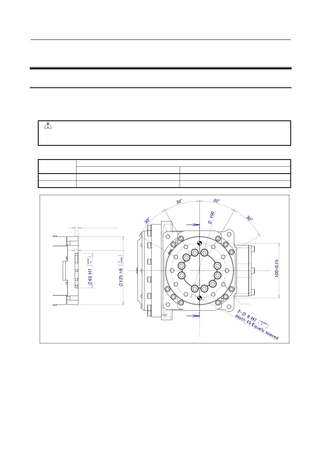
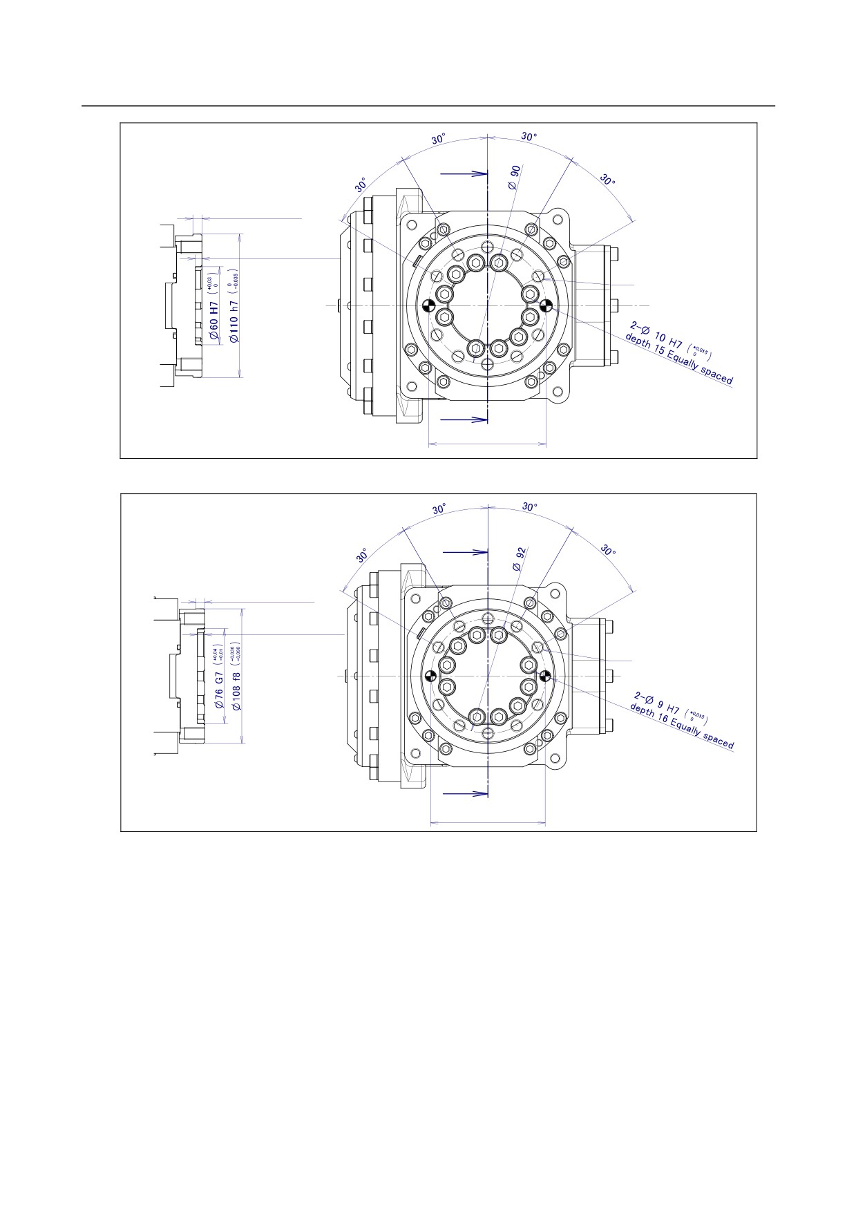
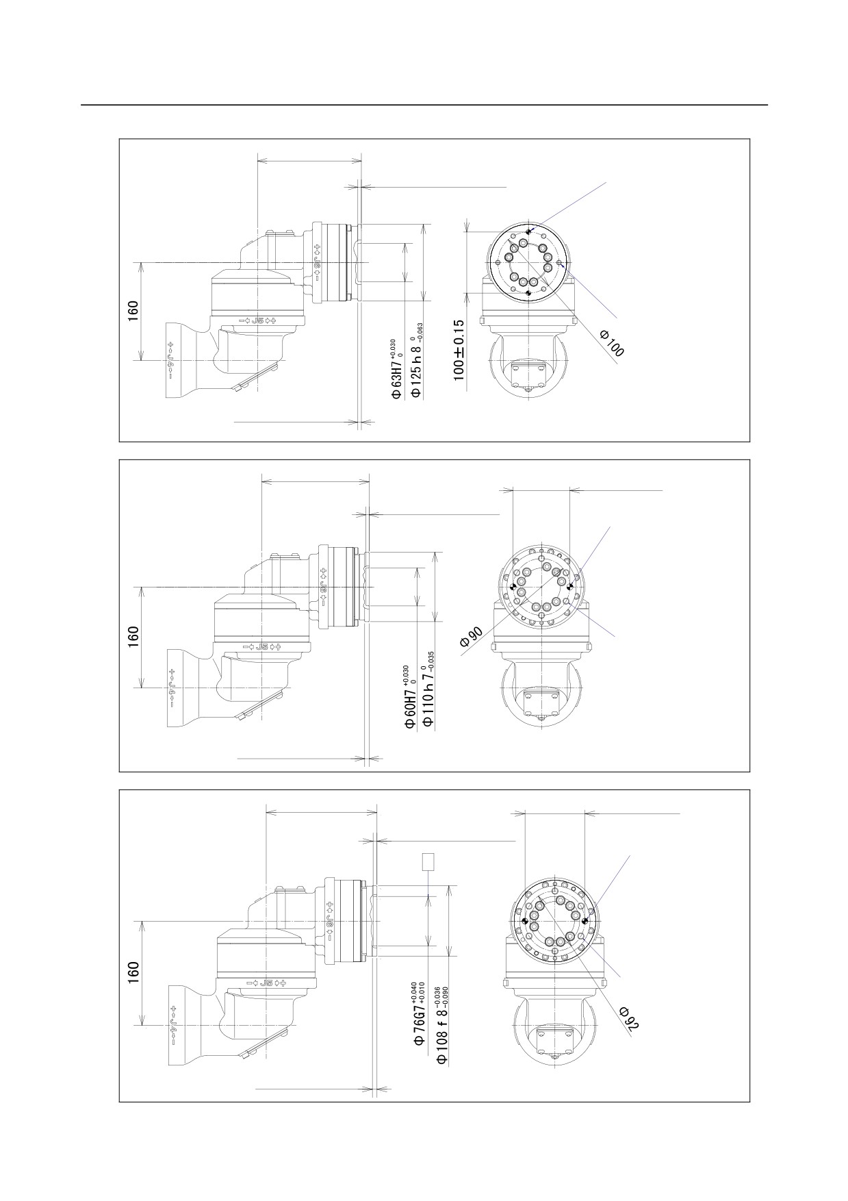
Fig. 4.1 (a) to (f) are the diagrams for installing end effectors on the wrist. Select screws and positioning
pins of a length that matches the depth of the tapped and pin holes. Fasten the bolt for fixing the end
effector with following torque.
CAUTION
Notice the tooling coupling depth to wrist flange should be shorter than the
flange coupling length.
Table 4.1 Hexagon socket head bolt
(Steel: strength rating of 12.9)
Nominal
Tightening torque N・m (kgf・cm)
diameter
Upper limit
Lower limit
M8
32 (330)
23 (230)
M10
66 (670)
46 (470)
㪍㩿O㪈㪉㪌㪿㪏㩷㫃㪼㫅㪾㫋㪿㪀
㪘
㪍 㪂㪇㪅㪊㩿O㪍㪊㪟㪎㩷㫃㪼㫅㪾㫋㪿㪀
㪈㪇㪄㪤㪏㩷㪻㪼㫇㫋㪿㩷㪈㪍
㪘
㪪㪼㪺㫋㫀㫆㫅㩷㪘㪄㪘
Fig. 4.1 (a) ISO flange, ISO rust protection flange (M-710iC/50, /70,/50H,/50S)
- 41 -
4.MECHANICAL COUPLING TO THE ROBOT
B-82274EN/09
㪘
㪎㩿O㪈㪈㪇㪿㪎㩷㫃㪼㫅㪾㫋㪿㪀
㪌 㪂㪇㪅㪊㩿O㪍㪇㪟㪎㩷㫃㪼㫅㪾㪿㪀
㪈㪇㪄㪤㪈㪇㩷㪻㪼㫇㫋㪿㩷㪈㪍
㪘
㪪㪼㪺㫋㫀㫆㫅㩷㪘㪄㪘
㪐㪇u㪇㪅㪈㪌
Fig. 4.1 (b) FANUC flange (M-710iC/50, /70, /50H ,/50S)
㪘
㪎㩿O㪈㪇㪏㪽㪏㩷㫃㪼㫅㪾㫋㪿㪀
㪍 㪂㪇㪅㪊㩿O㪎㪍㪞㪎㩷㫃㪼㫅㪾㫋㪿㪀
㪈㪇㪄㪤㪈㪇㩷㪻㪼㫇㫋㪿㩷㪈㪍
㪘
㪪㪼㪺㫋㫀㫆㫅㩷㪘㪄㪘
㪐㪉u㪇㪅㪈㪌
Fig. 4.1 (c) Special flange (M-710iC/50, /70, /50H, /50S)
- 42 -
B-82274EN/09
4.MECHANICAL COUPLING TO THE ROBOT
䎔䎚䎓
䎎䎓䎑䎖
䎙
䎃䎓 (Φ63H7)
2-Φ8H7䎃䎓䎑䎓䎔䎘
㪻㪼㫇㫋㪿㩷㪈㪌
㪍㪄㪤㪏
㪻㪼㫇㫋㪿㩷㪈㪍
㪼㫈㫌㪸㫃㫃㫐㩷㫊㫇㪼㪺㫀㪽㫀㪼㪻
6(Φ125h8)
Fig. 4.1 (d) ISO flange
(M-710iC/50E)
䎔䎚䎓
䎜䎓䏳䎓䎑䎔䎘
䎘䎃䎓䎑䎖 䎋䕎䎙䎓䎫䎚䎌
2-Φ10H7
䎓
㪻㪼㫇㫋㪿㩷㪈㪌
㪼㫈㫌㪸㫃㫃㫐㩷㫊㫇㪼㪺㫀㪽㫀㪼㪻
㪍㪄㪤㪈㪇
㪻㪼㫇㫋㪿㩷㪈㪍
㪼㫈㫌㪸㫃㫃㫐㩷㫊㫇㪼㪺㫀㪽㫀㪼㪻
7(Φ110h7)
Fig. 4.1 (e) FANUC flange (M-710iC/50E)
䎔䎚䎓
䎜䎕䏳䎓䎑䎔䎘
䎙䎃䎓䎑䎖(Φ76G7)
2-Φ9H7
䎓
䎻
㪻㪼㫇㫋㪿㩷㪈㪍
㪼㫈㫌㪸㫃㫃㫐㩷㫊㫇㪼㪺㫀㪽㫀㪼㪻
6-M10
㪻㪼㫇㫋㪿㩷㪈㪍
㪼㫈㫌㪸㫃㫃㫐㩷㫊㫇㪼㪺㫀㪽㫀㪼㪻
7(Φ108f8)
Fig. 4.1 (f) Special flange (M-710iC/50E)
- 43 -
4.MECHANICAL COUPLING TO THE ROBOT
B-82274EN/09
4.2
EQUIPMENT MOUNTING FACE
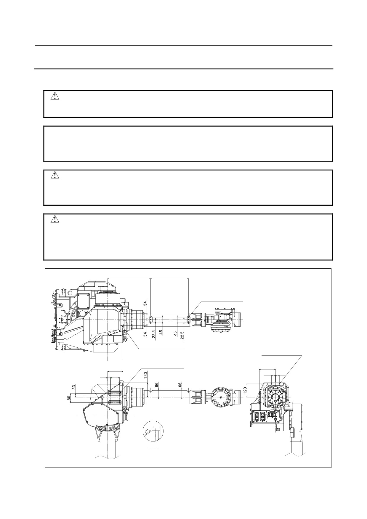
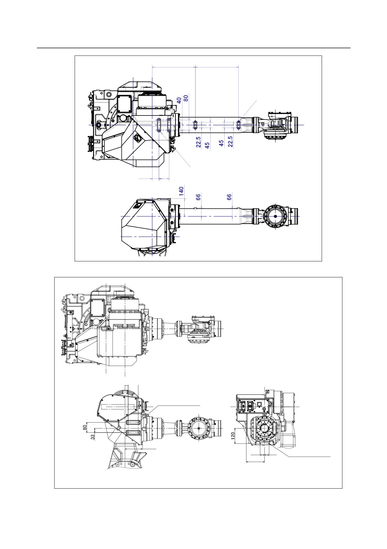
As shown in Fig. 4.2 (a) and (b) tapped holes are provided to install equipment to the robot.
CAUTION
Never perform additional machining operations such as drilling or tapping on the
robot body. This can seriously affect the safety and functions of the robot.
NOTE
Note that the use of a tapped hole not shown in the following figure is not
assured. Please do not tighten both with the tightening bolts used for mechanical
unit.
CAUTION
Equipments should be installed so that mechanical unit cable does not interfere.
If equipments interfere, the mechanical unit cable might be disconnected, and
unexpected troubles might occur.
CAUTION
・ Do not put load on J3 arm. (There is no problem for putting load on J3 casing.)
・ If equipment is installed to J3 arm, it is dangerous because it rotate with J3 arm.
(except M-710iC/50H)
・ If you put load on J3 arm, unavoidably, treat it as wrist load.
䎖䎛䎙
䎖䎗䎓
6-M8 Depth 12
(On J3 arm)
2-M8 Depth 16
(On J3 casing)
䎕䎐䎰䎛䎃䎧䏈䏓䏗䏋䎃䎔䎕
䎔䎕䎚
(On J3 casing)
4-M8 Depth 12
䎔䎗䎘
䎔䎖䎛
(On J3 casing)
䎖䎘
䎖䎘
䎕䎘
䎛䎓
䎤
䎔䎛
DETAIL A
Fig. 4.2 (a) Equipment mounting surfaces (M-710iC/50, /70, /50E)
- 44 -
B-82274EN/09
4.MECHANICAL COUPLING TO THE ROBOT
㪊㪋㪇
㪊㪋㪇
㪍㪄㪤㪏㩷㪛㪼㫇㫋㪿㩷㪈㪉
㩿㪦㫅㩷㪡㪊㩷㪸㫉㫄㪀
㪋㪄㪤㪏㩷㪛㪼㫇㫋㪿㩷㪈㪉
㩿㪦㫅㩷㪡㪊㩷㪺㪸㫊㫀㫅㪾㪀
㪌㪋
㪏㪇
Fig. 4.2 (b) Equipment mounting surfaces (M-710iC/50H)
䎕䎘 䎛䎓
4-M8 Depth 12
(On J3 casing)
䎔䎖䎛
䎖䎘
䎖䎘
2-M8 Depth 12
䎔䎗䎘
(On J3 casing)
Fig. 4.2 (c) Equipment mounting surfaces (M-710iC/50S)
- 45 -
4.MECHANICAL COUPLING TO THE ROBOT
B-82274EN/09
4.3
LOAD SETTING
NOTE
Set load condition parameter before robot runs. Do not operate the robot in over
payload. Don’t exceed allowable payload including connection cables and its
swing. Operation in over payload may occur troubles such as reducer life
reduction.
The motion performance screens include the MOTION PERFORMANCE screen, MOTION PAYLOAD
SET screen, and MOTION ARMLOAD SET screen. These screens are used to specify payload
information and equipment information on the robot.
1
Click the [MENUS] key to display the screen menu.
2
Select “6 SYSTEM” from the next page.
3
Click F1 ([TYPE]).
4
Select “MOTION.” The MOTION PERFORMANCE screen appears.
MOTION PERFORMANCE
JOINT
10 %
Group1
No. PAYLOAD[kg]
Comment
1
50.00
[
]
2
0.00
[
]
3
0.00
[
]
4
0.00
[
]
5
0.00
[
]
6
0.00
[
]
7
0.00
[
]
8
0.00
[
]
9
0.00
[
]
10
0.00
[
]
Active PAYLOAD number = 0
[ TYPE ] GROUP DETIAL ARMLOAD SETTND>
IDENT
>
5
Ten different pieces of payload information can be set using condition No. 1 to 10 on this screen.
Place the cursor on one of the numbers, and click F3 (DETAIL). The MOTION PAYLOAD SET
screen appears.
MOTION PAYLOAD SET
JOINT
100 %
Group1
1 Schedule No [
1]:
[ Comment
]
2 PAYLOAD
[ kg ]
50.00
3 PAYLOAD CENTER X [ cm ]
-26.00
4 PAYLOAD CENTER Y [ cm ]
0.00
5 PAYLOAD CENTER Z
[ cm ]
15.00
6 PAYLOAD INERTIA X [kgfcms^2 ]
4.307
7 PAYLOAD INERTIA Y [kgfcms^2 ]
6.699
8 PAYLOAD INERTIA Z
[kgfcms^2 ]
4.318
[ TYPE ] GROUP NUMBER DEFAULT HELP
- 46 -
B-82274EN/09
4.MECHANICAL COUPLING TO THE ROBOT
㪯
㪚㪼㫅㫋㪼㫉㩷㫆㪽㩷㫉㫆㪹㫆㫋
㪯
㪽㫃㪸㫅㪾㪼
㫐
㪱
㫄㪸㫊㫊㩷㫄㩿㫂㪾㪀
㫏㪾㩿㪺㫄㪀
㪉
㪚㪼㫅㫋㪼㫉㩷㫆㪽
㪚㪼㫅㫋㪼㫉㩷㫆㪽
㪾㫉㪸㫍㫀㫋㫐
㪾㫉㪸㫍㫀㫋㫐
㪠㫑㩷㩿㫂㪾㪽䊶㪺㫄䊶㫊㪉㪀
㫐㩷㩿㪺㫄㪀㪾
㪠㫏㩷㩿㫂㪾㪽䊶㪺㫄䊶㫊㪉㪀
㫑㪾㩿㪺㫄㪀
Fig. 4.3 Standard tool coordinate
6
Set the payload, gravity center position, and inertia around the gravity center on the MOTION
PAYLOAD SET screen. The X, Y, and Z directions displayed on this screen correspond to the
respective standard tool coordinates (with no tool coordinate system set up). When values are
entered, the following message appears:
“Path and Cycletime will change. Set it?” Respond to
the message with F4 ([YES]) or F5 ([NO]).
7
Clicking F3 ([NUMBER]) will bring you to the MOTION PAYLOAD SET screen for another
condition
8
Press the previous page key to return to the list screen. Press F5 SETIND, and enter a desired load
setting condition number.
9
On the list screen, pressing F4 ARMLOAD brings you to the device-setting screen.
MOTION ARMLOAD SET
JOINT
100 %
Group1
1 ARM LOAD AXIS #1 [ kg ]
0.00
2 ARM LOAD AXIS #3 [ kg ]
15.00
[ TYPE ] GROUP
DEFAULT HELP
10
Specify the mass of the loads on the J2 base and J3 casing. When you enter
ARM LOAD AXIS #1[kg] (Mass of the load on the J2 base) and ARM LOAD AXIS #3[kg] (Mass
of the load on the J3 arm), the confirmation message “Path and Cycletime will change. Set it?”
appears. Select F4 YES or F5 NO. Once the mass of a device is entered, it is put in effect by
turning the power off and on again.
- 47 -
5.PIPING AND WIRING TO THE END EFFECTOR
B-82274EN/09
5 PIPING AND WIRING TO THE END
EFFECTOR
WARNING
・ Use mechanical unit cables that have required user interface.
・ Don’t add user cable or hose to inside of mechanical unit.
・ Please do not obstruct the movement of the mechanical unit cable when cables are
added to outside of mechanical unit.
・ Please do not perform remodeling (Adding a protective cover and fix an outside cable
more) obstructing the behavior of the outcrop of the cable.
・ Please do not interfere with the other parts of mechanical unit when equipment is
installed in the robot.
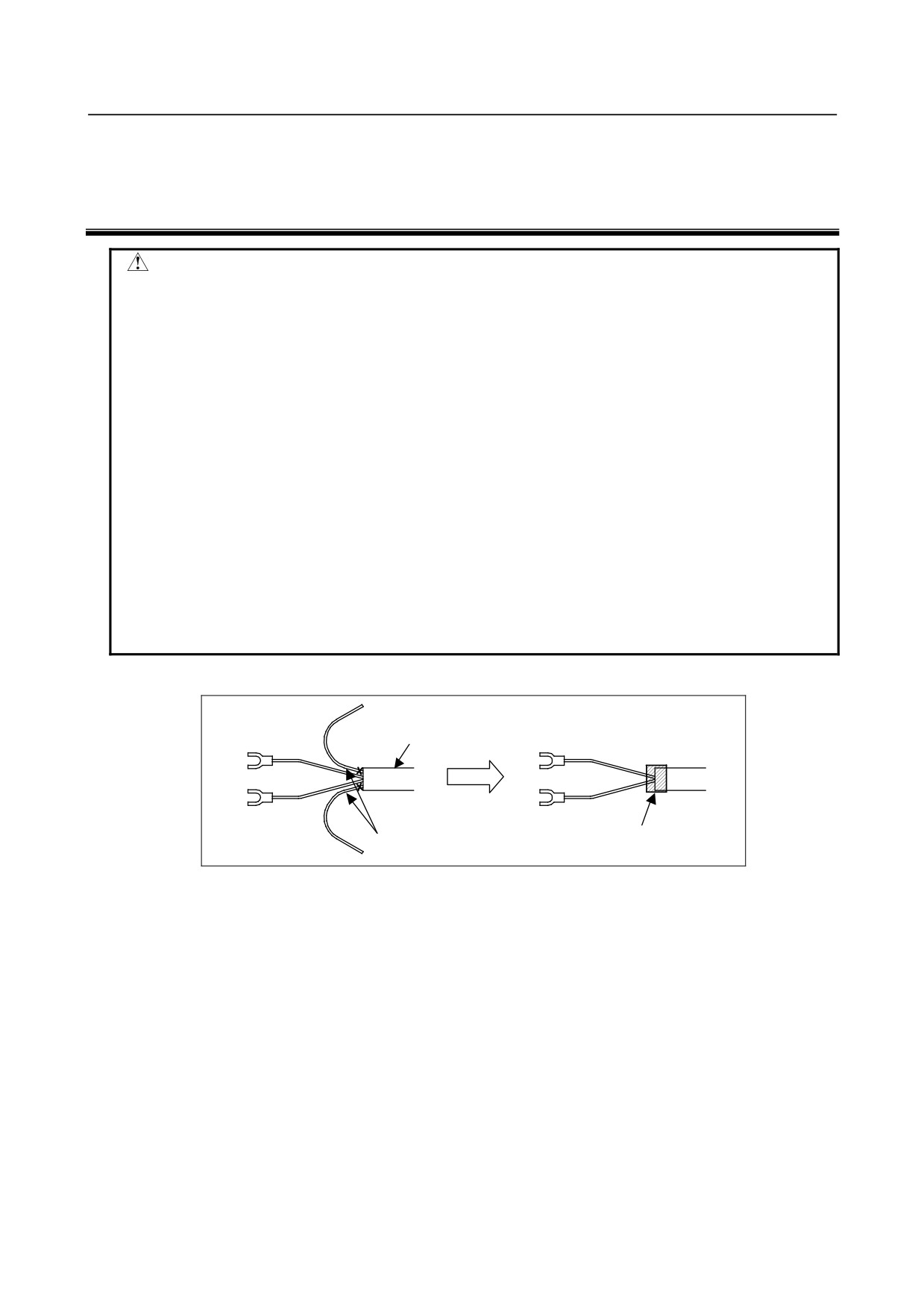
・ Cut unnecessary length of wire rod. Make insulation processing like winding acetate
tape.
・ If you can not prevent electrostatic charge of work and end effector, keep away an
end effector (a hand) cable from an end effector and a work as much as possible,
when wiring it. When they come to close unavoidable, make insulation processing
between them.
・ Be sure to seal connectors of hand side and robot side and terminal parts of cables,
to prevent water from entering the mechanical unit. Also, attach cover to unused
connector.
・ Check looseness of connector and wound of coating of cables routinely.
When these attentions are not kept, unexpected troubles might occur.
㪜㫅㪻㩷㪼㪽㪽㪼㪺㫋㫆㫉㩷㩿㪿㪸㫅㪻㪀㩷㪺㪸㪹㫃㪼㩷
㪚㫌㫋㩷㫌㫅㫅㪼㪺㪼㫊㫊㪸㫉㫐㩷㫃㪼㫅㪾㫋㪿㩷㫆㪽㩷㫌㫅㫌㫊㪼㪻㩷㫎㫀㫉㪼㩷㫉㫆㪻㩷 㪠㫅㫊㫌㫃㪸㫋㫀㫆㫅㩷㫇㫉㫆㪺㪼㫊㫊㫀㫅㪾㩷
Fig.5 Treatment method of end effector (hand) cable
- 48 -
B-82274EN/09
5.PIPING AND WIRING TO THE END EFFECTOR
5.1
AIR SUPPLY (OPTION)
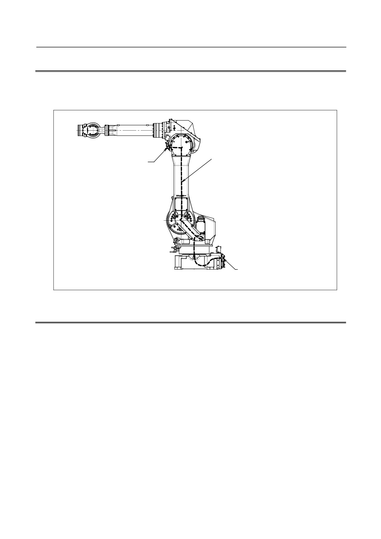
Robot has air inlet and air outlet on the side of the J1 base and the front of the J3 casing. The connector is
a Rc1/2 female (ISO).
As couplings are not supplied, it will be necessary to prepare couplings, which suit to the hose size.
㪘㫀㫉㩷㫋㫌㪹㪼㬍㪈㩷㫆㫉㩷㪉
㪪㫀㪾㫅㪸㫃㩷㪸㫀㫉㩷㫃㫀㫅㪼㩷䋺㩷㫇㪸㫅㪼㫃㩷㫌㫅㫀㫆㫅㩷㪯㩷㪈㩷㫆㫉
㪦㫌㫋㫊㫀㪻㪼㩷㪻㫀㪸㫄㪼㫋㪼㫉䇭㪈㪉㫄㫄
㪛㫌㪸㫃㩷㪸㫀㫉㩷㫃㫀㫅㪼㩷䋺䇭㫇㪸㫅㪼㫃㩷㫌㫅㫀㫆㫅㩷㪯㩷㪉
㪠㫅㫊㫀㪻㪼㩷㪻㫀㪸㫄㪼㫋㪼㫉䇭㪏㫄㫄
䇭㪩㪺㪈㪆㪉㩷㪽㪼㫄㪸㫃㪼㩷䋨㪘㫀㫉㩷㫆㫌㫋㫃㪼㫋㩷㫊㫀㪻㪼䋩
㪪㫀㪾㫅㪸㫃㩷㪸㫀㫉㩷㫃㫀㫅㪼㩷䋺㩷㫇㪸㫅㪼㫃㩷㫌㫅㫀㫆㫅㩷㪯㩷㪈㩷㫆㫉
㪛㫌㪸㫃㩷㪸㫀㫉㩷㫃㫀㫅㪼㩷䋺䇭㫇㪸㫅㪼㫃㩷㫌㫅㫀㫆㫅㩷㪯㩷㪉
䇭㪩㪺㪈㪆㪉㩷㪽㪼㫄㪸㫃㪼㩷䋨㪘㫀㫉㩷㫀㫅㫃㪼㫋㩷㫊㫀㪻㪼䋩
Fig. 5.1 Air supply (option)
5.2
AIR PIPING (OPTION)
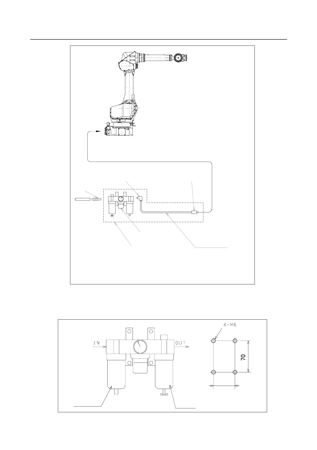
Fig. 5.2 (a) shows how to connect air hose to the robot. If the air control set is specified as an option, the
air hose between the mechanical unit and the air control set is provided. A tap holes shown in 5.3 figure
(b) are necessary for the installation of three points of air sets. Please prepare by customer.
- 49 -
5.PIPING AND WIRING TO THE END EFFECTOR
B-82274EN/09
㪜㫃㪹㫆㫎㩷㫅㫀㫇㫇㫃㪼㩷㪩㪊㪆㪏
㪪㫋㫉㪸㫀㪾㪿㫋㩷㫅㫀㫇㫇㫃㪼㩷㪩㪈㪆㪉
㪩㪊㪆㪏
㪘㫀㫉㩷㫋㫌㪹㪼
㪘㫀㫉㩷㪺㫆㫅㫋㫉㫆㫃㫃㩷㫊㪼㫋
㪘㫃㫃㩷㫃㪼㫅㪾㫋㪿㩷㪊㫄㩷
㪦㫌㫋㪼㫉㩷㪈㪉㫄㫄㩷
㪠㫅㩷㪻㫆㫋㫋㪼㪻㩷㫃㫀㫅㪼
㪠㫅㫊㫀㪻㪼㩷㪏㫄㫄
㪦㫇㫋㫀㫆㫅㪸㫃㩷㫇㪸㫉㫋㫊
㪥㪦㪫㪜㪀㩷㪧㫀㫇㪼㩷㫌㫊㪼㪻㩷㫀㫅㩷㫋㪿㪼㩷㫄㪼㪺㪿㪸㫅㫀㪺㪸㫃㩷㫌㫅㫀㫋㩷㪿㪸㫊㩷㪸㫅㩷㫆㫌㫋㪼㫉
㩷㩷㩷㩷㩷㩷㩷㩷㩷㩷㪻㫀㪸㫄㪼㫋㪼㫉㩷㫆㪽㩷㪈㪉㫄㫄㩷㪸㫅㪻㩷㪸㫅㩷㫀㫅㫅㪼㫉㩷㪻㫀㪸㫄㪼㫋㪼㫉㩷㫆㪽㩷㪏㫄㫄㪅
㩷㩷㩷㩷㩷㩷㩷㩷㩷㩷㪰㫆㫌㩷㪺㪸㫅㩷㫌㫊㪼㩷㪸㩷㪻㫀㪽㪽㪼㫉㪼㫅㫋㩷㫊㫀㫑㪼㩷㫇㫀㫇㪼㩷㫆㫌㫋㫊㫀㪻㪼㩷㫋㪿㪼㩷㫄㪼㪺㪿㪸㫅㫀㪺㪸㫃
㩷㩷㩷㩷㩷㩷㩷㩷㩷㩷㫌㫅㫀㫋㪅
Fig. 5.2 (a) Air piping (option)
Air control set
Fill the lubricator having three air components to the specified level with turbine oil#90 to # 140. The
machine tool builder is required to prepare mounting bolts.
㪍㪋㩷
Air filter
Lubricator
Fig. 5.2 (b) Air control set (option)
- 50 -
B-82274EN/09
5.PIPING AND WIRING TO THE END EFFECTOR
NOTE
The capacity values of the robot is determined as follows.
These values must not be exceeded.
Supply air pressure
0.49 to 0.69MPa(5 to 7kgf/cm2)
Air pressure
Setting: 0.49MPa(5kgf/cm2)
Amount of consumption
Maximum instantaneous amount 150Nl/min (0.15Nm3/min)
5.3
INTERFACE FOR OPTION CABLE (OPTION)
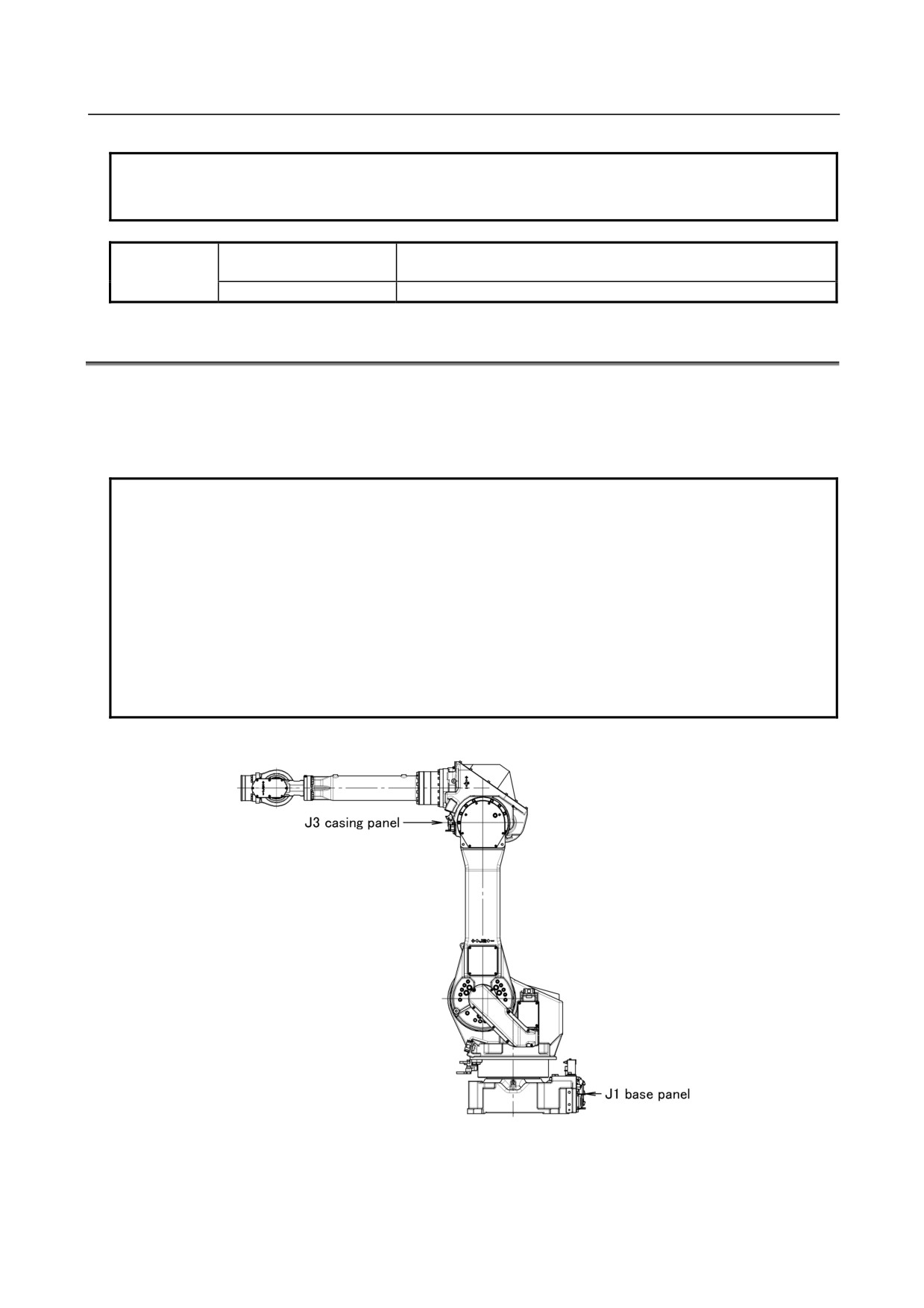
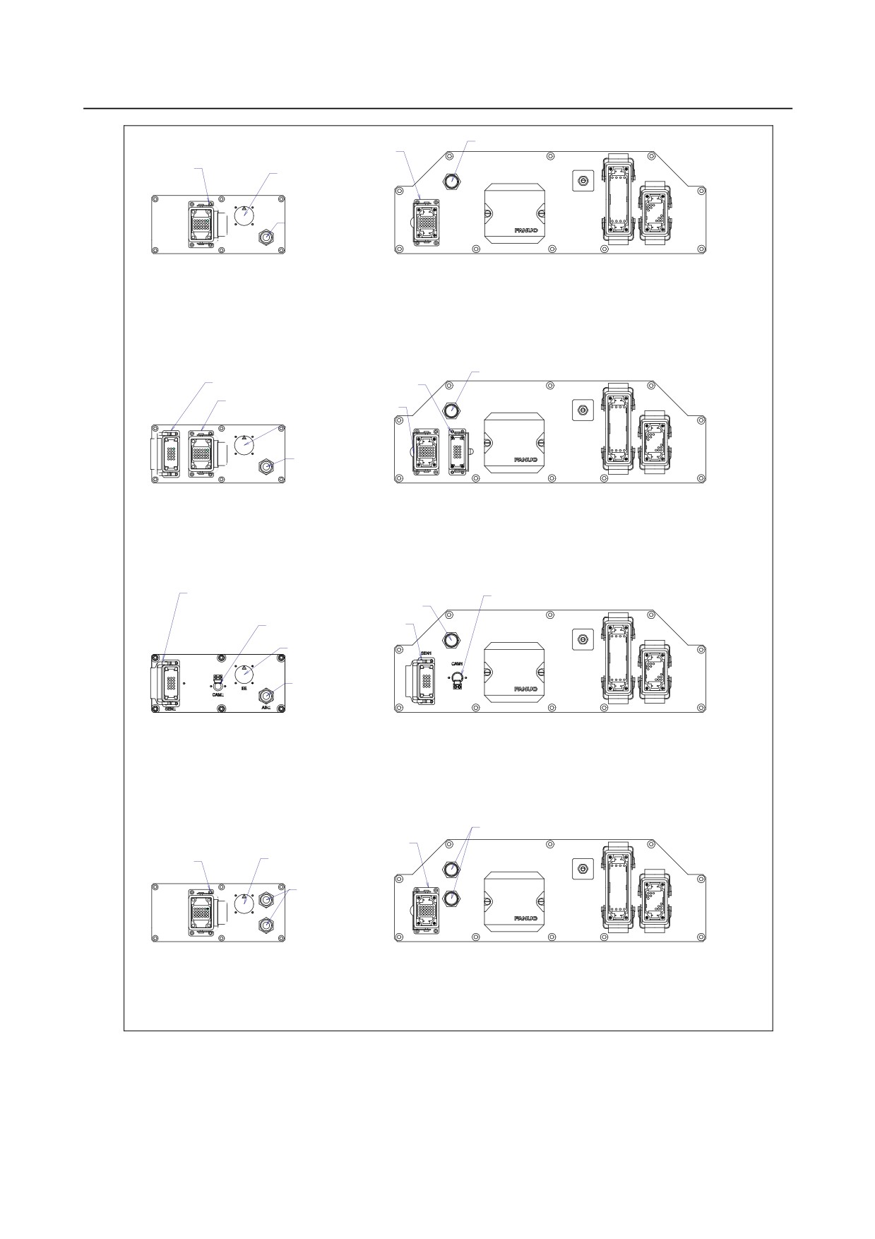
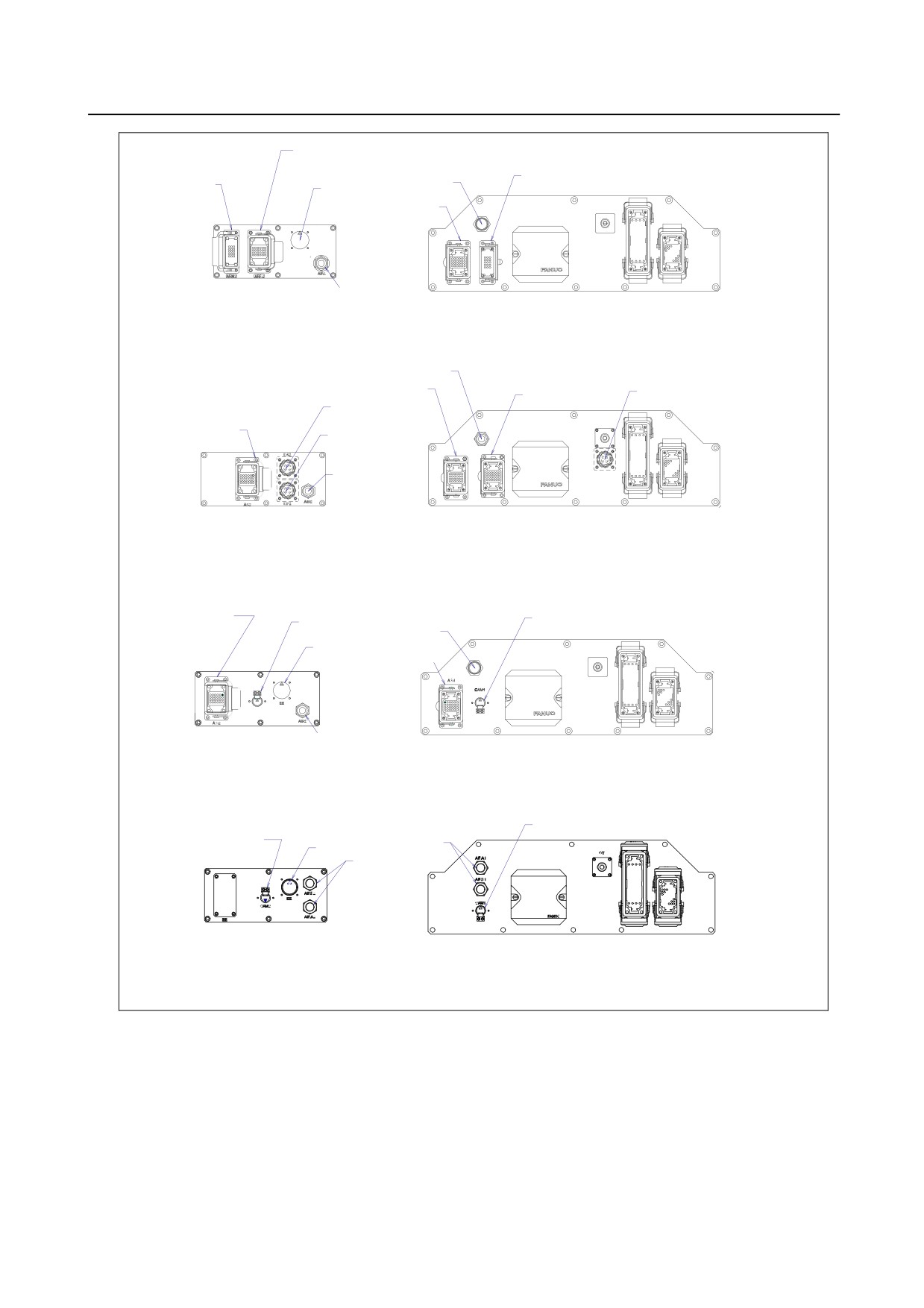
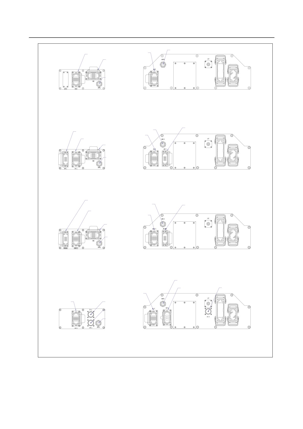
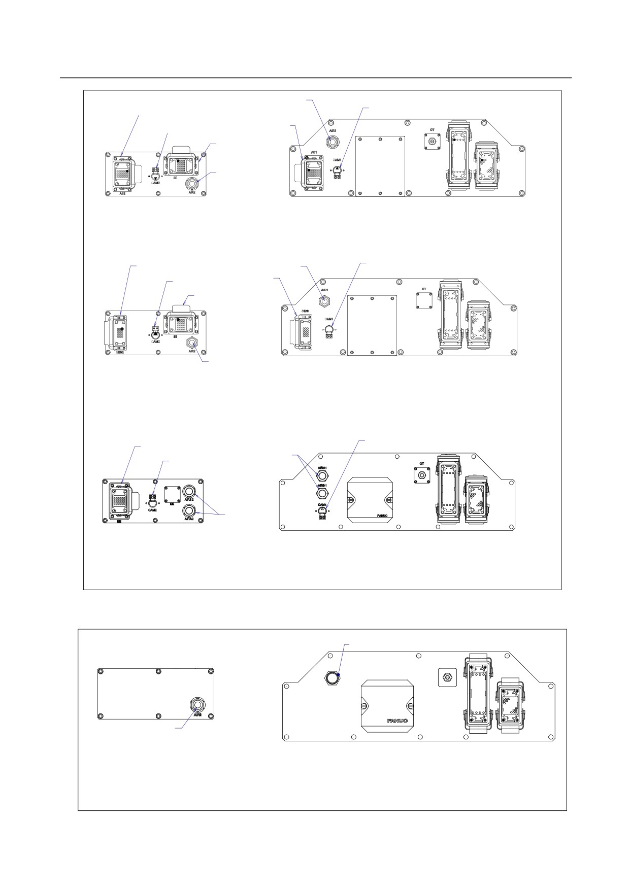
Fig. 5.3 (a) to (f) show the position of the option cable interface.
EE interface (RI/RO), user cable (signal line and power line), DeviceNet cable (signal and power line),
Additional axis motor cable, (Pulsecoder/power, brake), camera cable, 3DL sensor, force sensor are
prepared as options.
NOTE
Each option cable is written like below on connector panel
EE interface : EE
User cable (signal) : AS
User cable (power) : AP
Devicenet cable (signal) : DS
Devicenet cable (power) : DP
Additional axis motor cable (Pulsecoder) : ARP
Additional axis motor cable (power,brake) : ARM
Camera cable : CAM
3DL sensor cable : SEN
Fig. 5.3 (a) Position of the option cable interface (option)
- 51 -
5.PIPING AND WIRING TO THE END EFFECTOR
B-82274EN/09
䋨㪘㫀㫉㩷㫀㫅㫃㪼㫋䋩
㪬㫊㪼㫉㩷㪺㪸㪹㫃㪼㩷㩿㫊㫀㫅㪾㪸㫃㪀
㫀㫅㫋㪼㫉㪽㪸㪺㪼
㪬㫊㪼㫉㩷㪺㪸㪹㫃㪼㩷㩿㫊㫀㫅㪾㪸㫃㪀
A IR1
OT
㫀㫅㫋㪼㫉㪽㪸㪺㪼
㪜㪜㩷㫀㫅㫋㪼㫉㪽㪸㪺㪼
㩿㪩㪠㪆㪩㪦㪀
AS1
䋨㪘㫀㫉㩷㫆㫌㫋㫃㪼㫋䋩
EE
AS2
AIR2
㪡㪊㩷㪺㪸㫊㫀㫅㪾㩷㪺㫆㫅㫅㪼㪺㫋㫆㫉㩷㫇㫃㪸㫋㪼㩷㩿㫆㫌㫋㫇㫌㫋㩷㫊㫀㪻㪼㪀
㪡㪈㩷㪹㪸㫊㪼㩷㪺㫆㫅㫅㪼㪺㫋㫆㫉㩷㫇㫃㪸㫋㪼㩷㩿㫀㫅㫇㫌㫋㩷㫊㫀㪻㪼㪀
㪮㫀㫋㪿㩷㫌㫊㪼㫉㩷㪺㪸㪹㫃㪼㩷㩿㫊㫀㪾㫅㪸㫃㪀㩷㪸㫅㪻㩷㪸㫀㫉㩷㬍㪈
㪪㫇㪼㪺㪅㩷㫆㪽㩷㫄㪼㪺㪿㪸㫅㫀㪺㪸㫃㩷㫌㫅㫀㫋㩷㪺㪸㪹㫃㪼
㪘㪇㪌㪙㪄㪈㪈㪉㪌㪄㪟㪉㪇㪉㩷㩿㪤㪄㪎㪈㪇㫀㪚㪆㪌㪇㪃㩷㪆㪎㪇㪃㩷㪆㪌㪇㪜㪀
㪘㪇㪌㪙㪄㪈㪈㪉㪌㪄㪟㪌㪇㪉㩷㩿㪤㪄㪎㪈㪇㫀㪚㪆㪌㪇㪟㪀
㪘㪇㪌㪙㪄㪈㪈㪉㪌㪄㪟㪉㪉㪉㩷㩿㪤㪄㪎㪈㪇㫀㪚㪆㪌㪇㪪㪀
䋨㪘㫀㫉㩷㫀㫅㫃㪼㫋䋩
㪬㫊㪼㫉㩷㪺㪸㪹㫃㪼㩷㩿㫇㫆㫎㪼㫉㪀
㪬㫊㪼㫉㩷㪺㪸㪹㫃㪼㩷㩿㫊㫀㫅㪾㪸㫃㪀
㫀㫅㫋㪼㫉㪽㪸㪺㪼
㫀㫅㫋㪼㫉㪽㪸㪺㪼
AIR1
OT
㪬㫊㪼㫉㩷㪺㪸㪹㫃㪼㩷㩿㫊㫀㫅㪾㪸㫃㪀
㫀㫅㫋㪼㫉㪽㪸㪺㪼
㪬㫊㪼㫉㩷㪺㪸㪹㫃㪼㩷㩿㫊㫀㫅㪾㪸㫃㪀
㫀㫅㫋㪼㫉㪽㪸㪺㪼
㪜㪜㩷㫀㫅㫋㪼㫉㪽㪸㪺㪼
AS1
AP1
㩿㪩㪠㪆㪩㪦㪀
EE
䋨㪘㫀㫉㩷㫆㫌㫋㫃㪼㫋䋩
AP2
AS2
AIR2
㪡㪊㩷㪺㪸㫊㫀㫅㪾㩷㪺㫆㫅㫅㪼㪺㫋㫆㫉㩷㫇㫃㪸㫋㪼㩷㩿㫆㫌㫋㫇㫌㫋㩷㫊㫀㪻㪼㪀
㪡㪈㩷㪹㪸㫊㪼㩷㪺㫆㫅㫅㪼㪺㫋㫆㫉㩷㫇㫃㪸㫋㪼㩷㩿㫀㫅㫇㫌㫋㩷㫊㫀㪻㪼㪀
㪮㫀㫋㪿㩷㫌㫊㪼㫉㩷㪺㪸㪹㫃㪼㩷㩿㫊㫀㪾㫅㪸㫃㪆㫇㫆㫎㪼㫉㪀
㪪㫇㪼㪺㪅㩷㫆㪽㩷㫄㪼㪺㪿㪸㫅㫀㪺㪸㫃㩷㫌㫅㫀㫋㩷㪺㪸㪹㫃㪼
㪘㪇㪌㪙㪄㪈㪈㪉㪌㪄㪟㪉㪇㪋㩷㩿㪤㪄㪎㪈㪇㫀㪚㪆㪌㪇㪃㩷㪆㪎㪇㪃㩷㪌㪇㪜㪀
㪘㪇㪌㪙㪄㪈㪈㪉㪌㪄㪟㪌㪇㪋㩷㩿㪤㪄㪎㪈㪇㫀㪚㪆㪌㪇㪟㪀
㪘㪇㪌㪙㪄㪈㪈㪉㪌㪄㪟㪉㪉㪋㩷㩿㪤㪄㪎㪈㪇㫀㪚㪆㪌㪇㪪㪀
㪝㫆㫉㪺㪼㩷㫊㪼㫅㫊㫆㫉㪃㩷㪊㪛㪣㩷㫊㪼㫅㫊㫆㫉
㪚㪸㫄㪼㫉㪸㩷㪺㪸㪹㫃㪼
㫀㫅㫋㪼㫉㪽㪸㪺㪼
㫀㫅㫋㪼㫉㪽㪸㪺㪼
䋨㪘㫀㫉㩷㫀㫅㫃㪼㫋䋩
㪚㪸㫄㪼㫉㪸㩷㪺㪸㪹㫃㪼
㪝㫆㫉㪺㪼㩷㫊㪼㫅㫊㫆㫉㪃㩷㪊㪛㪣㩷㫊㪼㫅㫊㫆㫉
AIR1
OT
㫀㫅㫋㪼㫉㪽㪸㪺㪼
㫀㫅㫋㪼㫉㪽㪸㪺㪼
㪜㪜㩷㫀㫅㫋㪼㫉㪽㪸㪺㪼
㩿㪩㪠㪆㪩㪦㪀
䋨㪘㫀㫉㩷㫆㫌㫋㫃㪼㫋䋩
㪡㪊㩷㪺㪸㫊㫀㫅㪾㩷㪺㫆㫅㫅㪼㪺㫋㫆㫉㩷㫇㫃㪸㫋㪼㩷㩿㫆㫌㫋㫇㫌㫋㩷㫊㫀㪻㪼㪀
㪡㪈㩷㪹㪸㫊㪼㩷㪺㫆㫅㫅㪼㪺㫋㫆㫉㩷㫇㫃㪸㫋㪼㩷㩿㫀㫅㫇㫌㫋㩷㫊㫀㪻㪼㪀
㪮㫀㫋㪿㩷㪽㫆㫉㪺㪼㩷㫊㪼㫅㫊㫆㫉㩷㪃㩷㪊㪛㪣㩷㫊㪼㫅㫊㫆㫉㩷㩷㪸㫅㪻㩷㪺㪸㫄㪼㫉㪸㩷㪺㪸㪹㫃㪼
㪪㫇㪼㪺㪅㩷㫆㪽㩷㫄㪼㪺㪿㪸㫅㫀㪺㪸㫃㩷㫌㫅㫀㫋㩷㪺㪸㪹㫃㪼
㪘㪇㪌㪙㪄㪈㪈㪉㪌㪄㪟㪋㪇㪋㩷㩿㪤㪄㪎㪈㪇㫀㪚㪆㪌㪇㪃㩷㪆㪎㪇㪃㩷㪆㪌㪇㪜㪀
㪘㪇㪌㪙㪄㪈㪈㪉㪌㪄㪟㪋㪉㪉㩷㩿㪤㪄㪎㪈㪇㫀㪚㪆㪌㪇㪪㪀
䋨㪘㫀㫉㩷㫀㫅㫃㪼㫋䋩
㪬㫊㪼㫉㩷㪺㪸㪹㫃㪼㩷㩿㫊㫀㫅㪾㪸㫃㪀
㫀㫅㫋㪼㫉㪽㪸㪺㪼
AIRA1
OT
㪜㪜㩷㫀㫅㫋㪼㫉㪽㪸㪺㪼
㪬㫊㪼㫉㩷㪺㪸㪹㫃㪼㩷㩿㫊㫀㫅㪾㪸㫃㪀
㫀㫅㫋㪼㫉㪽㪸㪺㪼
㩿㪩㪠㪆㪩㪦㪀
AS1
AIRB1
䋨㪘㫀㫉㩷㫆㫌㫋㫃㪼㫋䋩
AIRB2
EE
AS2
AIRA2
㪡㪊㩷㪺㪸㫊㫀㫅㪾㩷㪺㫆㫅㫅㪼㪺㫋㫆㫉㩷㫇㫃㪸㫋㪼㩷㩿㫆㫌㫋㫇㫌㫋㩷㫊㫀㪻㪼㪀
㪡㪈㩷㪹㪸㫊㪼㩷㪺㫆㫅㫅㪼㪺㫋㫆㫉㩷㫇㫃㪸㫋㪼㩷㩿㫀㫅㫇㫌㫋㩷㫊㫀㪻㪼㪀
㪮㫀㫋㪿㩷㫌㫊㪼㫉㩷㪺㪸㪹㫃㪼㩷㩿㫊㫀㪾㫅㪸㫃㪀㩷㪸㫅㪻㩷㪸㫀㫉㩷㬍㪉
㪪㫇㪼㪺㪅㩷㫆㪽㩷㫄㪼㪺㪿㪸㫅㫀㪺㪸㫃㩷㫌㫅㫀㫋㩷㪺㪸㪹㫃㪼
㪘㪇㪌㪙㪄㪈㪈㪉㪌㪄㪟㪉㪇㪏㩷㩿㪤㪄㪎㪈㪇㫀㪚㪆㪌㪇㪃㩷㪆㪎㪇㪃㩷㪆㪌㪇㪜㪀
Fig. 5.3 (b) Interface for option cable 1/2
- 52 -
B-82274EN/09
5.PIPING AND WIRING TO THE END EFFECTOR
㪘㪻㪻㫀㫋㫀㫆㫅㪸㫃㩷㪸㫏㫀㫊㩷㫄㫆㫋㫆㫉㩷㪺㪸㪹㫃㪼
㩿㪧㫌㫃㫊㪼㪺㫆㪻㪼㫉㪀
㫀㫅㫋㪼㫉㪽㪸㪺㪼
㪘㪻㪻㫀㫋㫀㫆㫅㪸㫃㩷㪸㫏㫀㫊㩷㫄㫆㫋㫆㫉㩷㪺㪸㪹㫃㪼
㪘㪻㪻㫀㫋㫀㫆㫅㪸㫃㩷㪸㫏㫀㫊㩷㫄㫆㫋㫆㫉㩷㪺㪸㪹㫃㪼
䋨㪘㫀㫉㩷㫀㫅㫃㪼㫋䋩
㩿㫇㫆㫎㪼㫉㪃㩷㪹㫉㪸㫂㪼㪀
㩿㫇㫆㫎㪼㫉㪃㩷㪹㫉㪸㫂㪼㪀
㪜㪜㩷㫀㫅㫋㪼㫉㪽㪸㪺㪼
㫀㫅㫋㪼㫉㪽㪸㪺㪼
㫀㫅㫋㪼㫉㪽㪸㪺㪼
㩿㪩㪠㪆㪩㪦㪀
㪘㪻㪻㫀㫋㫀㫆㫅㪸㫃㩷㪸㫏㫀㫊㩷㫄㫆㫋㫆㫉㩷㪺㪸㪹㫃㪼
AIR1
OT
㩿㪧㫌㫃㫊㪼㪺㫆㪻㪼㫉㪀
㫀㫅㫋㪼㫉㪽㪸㪺㪼
ARP1
ARM1
EE
䋨㪘㫀㫉㩷㫆㫌㫋㫃㪼㫋䋩
㪡㪊㩷㪺㪸㫊㫀㫅㪾㩷㪺㫆㫅㫅㪼㪺㫋㫆㫉㩷㫇㫃㪸㫋㪼㩷㩿㫆㫌㫋㫇㫌㫋㩷㫊㫀㪻㪼㪀
㪡㪈㩷㪹㪸㫊㪼㩷㪺㫆㫅㫅㪼㪺㫋㫆㫉㩷㫇㫃㪸㫋㪼㩷㩿㫀㫅㫇㫌㫋㩷㫊㫀㪻㪼㪀
㪮㫀㫋㪿㩷㪸㪻㪻㫀㫋㫀㫆㫅㪸㫃㩷㪸㫏㫀㫊㩷㫄㫆㫋㫆㫉㩷㪺㪸㪹㫃㪼㩷㩿㪧㫌㫃㫊㪼㪺㫆㪻㪼㫉㪆㫇㫆㫎㪼㫉㪀
㪪㫇㪼㪺㪅㩷㫆㪽㩷㫄㪼㪺㪿㪸㫅㫀㪺㪸㫃㩷㫌㫅㫀㫋㩷㪺㪸㪹㫃㪼
㪘㪇㪌㪙㪄㪈㪈㪉㪌㪄㪟㪉㪇㪐㩷㩿㪤㪄㪎㪈㪇㫀㪚㪆㪌㪇㪃㩷㪆㪎㪇㪃㩷㪆㪌㪇㪜㪀
㪘㪇㪌㪙㪄㪈㪈㪉㪌㪄㪟㪉㪉㪐㩷㩿㪤㪄㪎㪈㪇㫀㪚㪆㪌㪇㪪㪀
䋨㪘㫀㫉㩷㫀㫅㫃㪼㫋䋩
㪬㫊㪼㫉㩷㪺㪸㪹㫃㪼㩷㩿㫊㫀㫅㪾㪸㫃㪀
㪛㪼㫍㫀㪺㪼㫅㪼㫋㩷㪺㪸㪹㫃㪼
㫀㫅㫋㪼㫉㪽㪸㪺㪼
㪛㪼㫍㫀㪺㪼㫅㪼㫋㩷㪺㪸㪹㫃㪼
㩿㫇㫆㫎㪼㫉㫃㪀㩷㫀㫅㫋㪼㫉㪽㪸㪺㪼
㩿㫊㫀㪾㫅㪸㫃㪀㩷㫀㫅㫋㪼㫉㪽㪸㪺㪼
㪛㪼㫍㫀㪺㪼㫅㪼㫋㩷㪺㪸㪹㫃㪼
㩿㫊㫀㪾㫅㪸㫃㪀㩷㫀㫅㫋㪼㫉㪽㪸㪺㪼
AIR1
OT
㪬㫊㪼㫉㩷㪺㪸㪹㫃㪼㩷㩿㫊㫀㫅㪾㪸㫃㪀
㫀㫅㫋㪼㫉㪽㪸㪺㪼
㪛㪼㫍㫀㪺㪼㫅㪼㫋㩷㪺㪸㪹㫃㪼
㩿㫇㫆㫎㪼㫉㪀㩷㫀㫅㫋㪼㫉㪽㪸㪺㪼
AS1
DP1
䋨㪘㫀㫉㩷㫆㫌㫋㫃㪼㫋䋩
DS1
㪡㪊㩷㪺㪸㫊㫀㫅㪾㩷㪺㫆㫅㫅㪼㪺㫋㫆㫉㩷㫇㫃㪸㫋㪼㩷㩿㫆㫌㫋㫇㫌㫋㩷㫊㫀㪻㪼㪀
㪡㪈㩷㪹㪸㫊㪼㩷㪺㫆㫅㫅㪼㪺㫋㫆㫉㩷㫇㫃㪸㫋㪼㩷㩿㫀㫅㫇㫌㫋㩷㫊㫀㪻㪼㪀
㪮㫀㫋㪿㩷㫌㫊㪼㫉㩷㪺㪸㪹㫃㪼㩿㫊㫀㪾㫅㪸㫃㪀㩷㪃㪻㪼㫍㫀㪺㪼㫅㪼㫋㩷㪺㪸㪹㫃㪼㩷㩿㫊㫀㪾㫅㪸㫃㪆㫇㫆㫎㪼㫉㪀
㪪㫇㪼㪺㪅㩷㫆㪽㩷㫄㪼㪺㪿㪸㫅㫀㪺㪸㫃㩷㫌㫅㫀㫋㩷㪺㪸㪹㫃㪼
㪘㪇㪌㪙㪄㪈㪈㪉㪌㪄㪟㪉㪈㪇㩷㩿㪤㪄㪎㪈㪇㫀㪚㪆㪌㪇㪃㩷㪆㪎㪇㪃㩷㪆㪌㪇㪜㪀
㪬㫊㪼㫉㩷㪺㪸㪹㫃㪼㩷㩿㫊㫀㫅㪾㪸㫃㩷㫌㫊㪸㪹㫃㪼㩷㫋㫆㩷㪽㫆㫉㪺㪼㩷
㪚㪸㫄㪼㫉㪸㩷㪺㪸㪹㫃㪼
㫊㪼㫅㫊㫆㫉㩷㪸㫅㪻㩷㪊㪛㪣㩷㫊㪼㫅㫊㫆㫉㪀
㪚㪸㫄㪼㫉㪸㩷㪺㪸㪹㫃㪼
㫀㫅㫋㪼㫉㪽㪸㪺㪼
㫀㫅㫋㪼㫉㪽㪸㪺㪼
㫀㫅㫋㪼㫉㪽㪸㪺㪼
䋨㪘㫀㫉㩷㫀㫅㫃㪼㫋䋩
㪜㪜㩷㫀㫅㫋㪼㫉㪽㪸㪺㪼
㩿㪩㪠㪆㪩㪦㪀
䎤䎬䎵䎔
䎲䎷
㪬㫊㪼㫉㩷㪺㪸㪹㫃㪼㩷㩿㫊㫀㫅㪾㪸㫃㩷㫌㫊㪸㪹㫃㪼㩷㫋㫆㩷㪽㫆㫉㪺㪼㩷
㫊㪼㫅㫊㫆㫉㩷㪸㫅㪻㩷㪊㪛㪣㩷㫊㪼㫅㫊㫆㫉㪀
㫀㫅㫋㪼㫉㪽㪸㪺㪼
䋨㪘㫀㫉㩷㫆㫌㫋㫃㪼㫋䋩
㪡㪊㩷㪺㪸㫊㫀㫅㪾㩷㪺㫆㫅㫅㪼㪺㫋㫆㫉㩷㫇㫃㪸㫋㪼㩷㩿㫆㫌㫋㫇㫌㫋㩷㫊㫀㪻㪼㪀
㪡㪈㩷㪹㪸㫊㪼㩷㪺㫆㫅㫅㪼㪺㫋㫆㫉㩷㫇㫃㪸㫋㪼㩷㩿㫀㫅㫇㫌㫋㩷㫊㫀㪻㪼㪀
㪮㫀㫋㪿㩷㫌㫊㪼㫉㩷㪺㪸㪹㫃㪼㩿㫊㫀㪾㫅㪸㫃㩷㫌㫊㪸㪹㫃㪼㩷㫋㫆㩷㪽㫆㫉㪺㪼㩷㫊㪼㫅㫊㫆㫉㩷㪸㫅㪻㩷㪊㪛㪣㩷㫊㪼㫅㫊㫆㫉㪀㩷㪸㫅㪻㩷㪺㪸㫄㪼㫉㪸㩷㪺㪸㪹㫃㪼
㪪㫇㪼㪺㪅㩷㫆㪽㩷㫄㪼㪺㪿㪸㫅㫀㪺㪸㫃㩷㫌㫅㫀㫋㩷㪺㪸㪹㫃㪼
㪘㪇㪌㪙㪄㪈㪈㪉㪌㪄㪟㪋㪇㪊㩷㩿㪤㪄㪎㪈㪇㫀㪚㪆㪌㪇㪃㩷㪆㪎㪇㪃㩷㪆㪌㪇㪜㪀
㪘㪇㪌㪙㪄㪈㪈㪉㪌㪄㪟㪋㪉㪈㩷㩿㪤㪄㪎㪈㪇㫀㪚㪆㪌㪇㪪㪀
㪚㪸㫄㪼㫉㪸㩷㪺㪸㪹㫃㪼
㫀㫅㫋㪼㫉㪽㪸㪺㪼
㪚㪸㫄㪼㫉㪸㩷㪺㪸㪹㫃㪼
䋨㪘㫀㫉㩷㫀㫅㫃㪼㫋䋩
㫀㫅㫋㪼㫉㪽㪸㪺㪼
㪜㪜㩷㫀㫅㫋㪼㫉㪽㪸㪺㪼
㩿㪩㪠㪆㪩㪦㪀
䋨㪘㫀㫉㩷㫆㫌㫋㫃㪼㫋䋩
㪡㪊㩷㪺㪸㫊㫀㫅㪾㩷㪺㫆㫅㫅㪼㪺㫋㫆㫉㩷㫇㫃㪸㫋㪼㩷㩿㫆㫌㫋㫇㫌㫋㩷㫊㫀㪻㪼㪀
㪡㪈㩷㪹㪸㫊㪼㩷㪺㫆㫅㫅㪼㪺㫋㫆㫉㩷㫇㫃㪸㫋㪼㩷㩿㫀㫅㫇㫌㫋㩷㫊㫀㪻㪼㪀
㪮㫀㫋㪿㩷㪺㪸㫄㪼㫉㪸㩷㪺㪸㪹㫃㪼㩷㪸㫅㪻㩷㪘㪠㪩㪯㪉
㪪㫇㪼㪺㪅㩷㫆㪽㩷㫄㪼㪺㪿㪸㫅㫀㪺㪸㫃㩷㫌㫅㫀㫋㩷㪺㪸㪹㫃㪼
㪘㪇㪌㪙㪄㪈㪈㪉㪌㪄㪟㪋㪇㪌㩷㩿㪤㪄㪎㪈㪇㫀㪚㪆㪌㪇㪃㩷㪆㪎㪇㪃㩷㪆㪌㪇㪜㪀
Fig. 5.3 (c) Interface for option cable 2/2
- 53 -
5.PIPING AND WIRING TO THE END EFFECTOR
B-82274EN/09
䋨㪘㫀㫉㩷㫀㫅㫃㪼㫋䋩
㪬㫊㪼㫉㩷㪺㪸㪹㫃㪼㩷㩿㫊㫀㫅㪾㪸㫃㪀
㪬㫊㪼㫉㩷㪺㪸㪹㫃㪼㩷㩿㫊㫀㫅㪾㪸㫃㪀
㫀㫅㫋㪼㫉㪽㪸㪺㪼
㫀㫅㫋㪼㫉㪽㪸㪺㪼
㪜㪜㩷㫀㫅㫋㪼㫉㪽㪸㪺㪼
㩿㪩㪠㪆㪩㪦㪀
䋨㪘㫀㫉㩷㫆㫌㫋㫃㪼㫋䋩
㪡㪊㩷㪺㪸㫊㫀㫅㪾㩷㪺㫆㫅㫅㪼㪺㫋㫆㫉㩷㫇㫃㪸㫋㪼㩷㩿㫆㫌㫋㫇㫌㫋㩷㫊㫀㪻㪼㪀
㪡㪈㩷㪹㪸㫊㪼㩷㪺㫆㫅㫅㪼㪺㫋㫆㫉㩷㫇㫃㪸㫋㪼㩷㩿㫀㫅㫇㫌㫋㩷㫊㫀㪻㪼㪀
㪮㫀㫋㪿㩷㫌㫊㪼㫉㩷㪺㪸㪹㫃㪼㩷㩿㫊㫀㪾㫅㪸㫃㪀㩷㪸㫅㪻㩷㪸㫀㫉㩷㬍㪈
㪪㫇㪼㪺㩷㫆㪽㩷㫄㪼㪺㪿㪸㫅㫀㪺㪸㫃㩷㫌㫅㫀㫋㩷㪺㪸㪹㫃㪼
㪘㪇㪌㪙㪄㪈㪈㪉㪌㪄㪟㪉㪇㪉㩷㩿㪤㪄㪎㪈㪇㫀㪚㪆㪌㪇㪃㩷㪆㪎㪇㪀
㪘㪇㪌㪙㪄㪈㪈㪉㪌㪄㪟㪉㪉㪉㩷㩿㪤㪄㪎㪈㪇㫀㪚㪆㪌㪇㪪㪀
㪬㫊㪼㫉㩷㪺㪸㪹㫃㪼㩷㩿㫊㫀㫅㪾㪸㫃㪀
䋨㪘㫀㫉㩷㫀㫅㫃㪼㫋䋩
㫀㫅㫋㪼㫉㪽㪸㪺㪼
㪬㫊㪼㫉㩷㪺㪸㪹㫃㪼㩷㩿㫊㫀㫅㪾㪸㫃㪀
㫀㫅㫋㪼㫉㪽㪸㪺㪼
㪬㫊㪼㫉㩷㪺㪸㪹㫃㪼㩷㩿㫊㫀㫅㪾㪸㫃㪀
㪬㫊㪼㫉㩷㪺㪸㪹㫃㪼㩷㩿㫊㫀㫅㪾㪸㫃㪀
㫀㫅㫋㪼㫉㪽㪸㪺㪼
㫀㫅㫋㪼㫉㪽㪸㪺㪼
㪜㪜㩷㫀㫅㫋㪼㫉㪽㪸㪺㪼
㩿㪩㪠㪆㪩㪦㪀
䋨㪘㫀㫉㩷㫆㫌㫋㫃㪼㫋䋩
㪡㪊㩷㪺㪸㫊㫀㫅㪾㩷㪺㫆㫅㫅㪼㪺㫋㫆㫉㩷㫇㫃㪸㫋㪼㩷㩿㫆㫌㫋㫇㫌㫋㩷㫊㫀㪻㪼㪀
㪡㪈㩷㪹㪸㫊㪼㩷㪺㫆㫅㫅㪼㪺㫋㫆㫉㩷㫇㫃㪸㫋㪼㩷㩿㫀㫅㫇㫌㫋㩷㫊㫀㪻㪼㪀
㪮㫀㫋㪿㩷㫌㫊㪼㫉㩷㪺㪸㪹㫃㪼㩷㩿㫊㫀㪾㫅㪸㫃㪆㫇㫆㫎㪼㫉㪀
㪪㫇㪼㪺㪅㩷㫆㪽㩷㫄㪼㪺㪿㪸㫅㫀㪺㪸㫃㩷㫌㫅㫀㫋㩷㪺㪸㪹㫃㪼
㪘㪇㪌㪙㪄㪈㪈㪉㪌㪄㪟㪉㪇㪋㩷㩿㪤㪄㪎㪈㪇㫀㪚㪆㪌㪇㪃㩷㪆㪎㪇㪀
㪘㪇㪌㪙㪄㪈㪈㪉㪌㪄㪟㪉㪉㪋㩷㩿㪤㪄㪎㪈㪇㫀㪚㪆㪌㪇㪪㪀
㪘㪻㪻㫀㫋㫀㫆㫅㪸㫃㩷㪸㫏㫀㫊㩷㫄㫆㫋㫆㫉㩷㪺㪸㪹㫃㪼
㩿㫇㫆㫎㪼㫉㪃㩷㪹㫉㪸㫂㪼㪀
㫀㫅㫋㪼㫉㪽㪸㪺㪼
䋨㪘㫀㫉㩷㫀㫅㫃㪼㫋䋩
㪘㪻㪻㫀㫋㫀㫆㫅㪸㫃㩷㪸㫏㫀㫊㩷㫄㫆㫋㫆㫉㩷㪺㪸㪹㫃㪼
㩿㫇㫆㫎㪼㫉㪃㩷㪹㫉㪸㫂㪼㪀
㪘㪻㪻㫀㫋㫀㫆㫅㪸㫃㩷㪸㫏㫀㫊㩷㫄㫆㫋㫆㫉㩷㪺㪸㪹㫃㪼
㫀㫅㫋㪼㫉㪽㪸㪺㪼
㩿㪧㫌㫃㫊㪼㪺㫆㪻㪼㫉㪀
㫀㫅㫋㪼㫉㪽㪸㪺㪼
㪘㪻㪻㫀㫋㫀㫆㫅㪸㫃㩷㪸㫏㫀㫊㩷㫄㫆㫋㫆㫉㩷㪺㪸㪹㫃㪼
㩿㪧㫌㫃㫊㪼㪺㫆㪻㪼㫉㪀
㫀㫅㫋㪼㫉㪽㪸㪺㪼
㪜㪜㩷㫀㫅㫋㪼㫉㪽㪸㪺㪼
㩿㪩㪠㪆㪩㪦㪀
䋨㪘㫀㫉㩷㫆㫌㫋㫃㪼㫋䋩
㪡㪊㩷㪺㪸㫊㫀㫅㪾㩷㪺㫆㫅㫅㪼㪺㫋㫆㫉㩷㫇㫃㪸㫋㪼㩷㩿㫆㫌㫋㫇㫌㫋㩷㫊㫀㪻㪼㪀
㪡㪈㩷㪹㪸㫊㪼㩷㪺㫆㫅㫅㪼㪺㫋㫆㫉㩷㫇㫃㪸㫋㪼㩷㩿㫀㫅㫇㫌㫋㩷㫊㫀㪻㪼㪀
㪮㫀㫋㪿㩷㪸㪻㪻㫀㫋㫀㫆㫅㪸㫃㩷㪸㫏㫀㫊㩷㫄㫆㫋㫆㫉㩷㪺㪸㪹㫃㪼㩷㩿㪧㫌㫃㫊㪼㪺㫆㪻㪼㫉㪆㫇㫆㫎㪼㫉㪀
㪪㫇㪼㪺㪅㩷㫆㪽㩷㫄㪼㪺㪿㪸㫅㫀㪺㪸㫃㩷㫌㫅㫀㫋㩷㪺㪸㪹㫃㪼
㪘㪇㪌㪙㪄㪈㪈㪉㪌㪄㪟㪉㪇㪐㩷㩿㪤㪄㪎㪈㪇㫀㪚㪆㪌㪇㪃㩷㪆㪎㪇㪀
㪘㪇㪌㪙㪄㪈㪈㪉㪌㪄㪟㪉㪉㪐㩷㩿㪤㪄㪎㪈㪇㫀㪚㪆㪌㪇㪪㪀
䋨㪘㫀㫉㩷㫀㫅㫃㪼㫋䋩
㪛㪼㫍㫀㪺㪼㫅㪼㫋㩷㪺㪸㪹㫃㪼
㪛㪼㫍㫀㪺㪼㫅㪼㫋㩷㪺㪸㪹㫃㪼
㩿㫇㫆㫎㪼㫉㪀㩷㫀㫅㫋㪼㫉㪽㪸㪺㪼
㩿㫊㫀㪾㫅㪸㫃㪀㩷㫀㫅㫋㪼㫉㪽㪸㪺㪼
㪬㫊㪼㫉㩷㪺㪸㪹㫃㪼㩷㩿㫊㫀㫅㪾㪸㫃㪀
㫀㫅㫋㪼㫉㪽㪸㪺㪼
㪬㫊㪼㫉㩷㪺㪸㪹㫃㪼㩷㩿㫊㫀㫅㪾㪸㫃㪀
㪛㪼㫍㫀㪺㪼㫅㪼㫋㩷㪺㪸㪹㫃㪼
㫀㫅㫋㪼㫉㪽㪸㪺㪼
㩿㫊㫀㪾㫅㪸㫃㪀㩷㫀㫅㫋㪼㫉㪽㪸㪺㪼
㪛㪼㫍㫀㪺㪼㫅㪼㫋㩷㪺㪸㪹㫃㪼
㩿㫇㫆㫎㪼㫉㪀㩷㫀㫅㫋㪼㫉㪽㪸㪺㪼
䋨㪘㫀㫉㩷㫆㫌㫋㫃㪼㫋䋩
㪡㪊㩷㪺㪸㫊㫀㫅㪾㩷㪺㫆㫅㫅㪼㪺㫋㫆㫉㩷㫇㫃㪸㫋㪼㩷㩿㫆㫌㫋㫇㫌㫋㩷㫊㫀㪻㪼㪀
㪡㪈㩷㪹㪸㫊㪼㩷㪺㫆㫅㫅㪼㪺㫋㫆㫉㩷㫇㫃㪸㫋㪼㩷㩿㫀㫅㫇㫌㫋㩷㫊㫀㪻㪼㪀
㪮㫀㫋㪿㩷㫌㫊㪼㫉㩷㪺㪸㪹㫃㪼㩿㫊㫀㪾㫅㪸㫃㪀㩷㪃㪻㪼㫍㫀㪺㪼㫅㪼㫋㩷㪺㪸㪹㫃㪼㩷㩿㫊㫀㪾㫅㪸㫃㪆㫇㫆㫎㪼㫉㪀
㪪㫇㪼㪺㪅㩷㫆㪽㩷㫄㪼㪺㪿㪸㫅㫀㪺㪸㫃㩷㫌㫅㫀㫋㩷㪺㪸㪹㫃㪼
㪘㪇㪌㪙㪄㪈㪈㪉㪌㪄㪟㪉㪈㪇㩷㩿㪤㪄㪎㪈㪇㫀㪚㪆㪌㪇㪃㩷㪆㪎㪇㪀
Fig. 5.3 (d) Interface for option cable
(When Severe dust/liquid protection package is specified) 1/2
- 54 -
B-82274EN/09
5.PIPING AND WIRING TO THE END EFFECTOR
䋨㪘㫀㫉㩷㫀㫅㫃㪼㫋䋩
㪚㪸㫄㪼㫉㪸㩷㪺㪸㪹㫃㪼
㪬㫊㪼㫉㩷㪺㪸㪹㫃㪼㩷㩿㫊㫀㫅㪾㪸㫃㪀
㫀㫅㫋㪼㫉㪽㪸㪺㪼
㫀㫅㫋㪼㫉㪽㪸㪺㪼
㪬㫊㪼㫉㩷㪺㪸㪹㫃㪼㩷㩿㫊㫀㫅㪾㪸㫃㪀
㪚㪸㫄㪼㫉㪸㩷㪺㪸㪹㫃㪼
㫀㫅㫋㪼㫉㪽㪸㪺㪼
㫀㫅㫋㪼㫉㪽㪸㪺㪼
㪜㪜㩷㫀㫅㫋㪼㫉㪽㪸㪺㪼
㩿㪩㪠㪆㪩㪦㪀
䋨㪘㫀㫉㩷㫆㫌㫋㫃㪼㫋䋩
㪡㪊㩷㪺㪸㫊㫀㫅㪾㩷㪺㫆㫅㫅㪼㪺㫋㫆㫉㩷㫇㫃㪸㫋㪼㩷㩿㫆㫌㫋㫇㫌㫋㩷㫊㫀㪻㪼㪀
㪡㪈㩷㪹㪸㫊㪼㩷㪺㫆㫅㫅㪼㪺㫋㫆㫉㩷㫇㫃㪸㫋㪼㩷㩿㫀㫅㫇㫌㫋㩷㫊㫀㪻㪼㪀
㪮㫀㫋㪿㩷㫌㫊㪼㫉㩷㪺㪸㪹㫃㪼㩿㫊㫀㪾㫅㪸㫃㪀㩷㪸㫅㪻㩷㪺㪸㫄㪼㫉㪸㩷㪺㪸㪹㫃㪼
㪪㫇㪼㪺㪅㩷㫆㪽㩷㫄㪼㪺㪿㪸㫅㫀㪺㪸㫃㩷㫌㫅㫀㫋㩷㪺㪸㪹㫃㪼
㪘㪇㪌㪙㪄㪈㪈㪉㪌㪄㪟㪋㪇㪊㩷㩿㪤㪄㪎㪈㪇㫀㪚㪆㪌㪇㪃㩷㪆㪎㪇㪀
㪘㪇㪌㪙㪄㪈㪈㪉㪌㪄㪟㪋㪉㪈㩷㩿㪤㪄㪎㪈㪇㫀㪚㪆㪌㪇㪪㪀
㪚㪸㫄㪼㫉㪸㩷㪺㪸㪹㫃㪼
㪝㫆㫉㪺㪼㩷㫊㪼㫅㫊㫆㫉㪃㩷㪊㪛㪣㩷㫊㪼㫅㫊㫆㫉
䋨㪘㫀㫉㩷㫀㫅㫃㪼㫋䋩
㫀㫅㫋㪼㫉㪽㪸㪺㪼
㫀㫅㫋㪼㫉㪽㪸㪺㪼
㪝㫆㫉㪺㪼㩷㫊㪼㫅㫊㫆㫉㪃㩷㪊㪛㪣㩷㫊㪼㫅㫊㫆㫉
㪚㪸㫄㪼㫉㪸㩷㪺㪸㪹㫃㪼
㫀㫅㫋㪼㫉㪽㪸㪺㪼
㫀㫅㫋㪼㫉㪽㪸㪺㪼
㪜㪜㩷㫀㫅㫋㪼㫉㪽㪸㪺㪼
㩿㪩㪠㪆㪩㪦㪀
䋨㪘㫀㫉㩷㫆㫌㫋㫃㪼㫋䋩
㪡㪊㩷㪺㪸㫊㫀㫅㪾㩷㪺㫆㫅㫅㪼㪺㫋㫆㫉㩷㫇㫃㪸㫋㪼㩷㩿㫆㫌㫋㫇㫌㫋㩷㫊㫀㪻㪼㪀
㪡㪈㩷㪹㪸㫊㪼㩷㪺㫆㫅㫅㪼㪺㫋㫆㫉㩷㫇㫃㪸㫋㪼㩷㩿㫀㫅㫇㫌㫋㩷㫊㫀㪻㪼㪀
㪮㫀㫋㪿㩷㪽㫆㫉㪺㪼㩷㫊㪼㫅㫊㫆㫉㩷㪃㩷㪊㪛㪣㩷㫊㪼㫅㫊㫆㫉㩷㩷㪸㫅㪻㩷㪺㪸㫄㪼㫉㪸㩷㪺㪸㪹㫃㪼
㪪㫇㪼㪺㪅㩷㫆㪽㩷㫄㪼㪺㪿㪸㫅㫀㪺㪸㫃㩷㫌㫅㫀㫋㩷㪺㪸㪹㫃㪼
㪘㪇㪌㪙㪄㪈㪈㪉㪌㪄㪟㪋㪇㪋㩷㩿㪤㪄㪎㪈㪇㫀㪚㪆㪌㪇㪃㩷㪆㪎㪇㪀
㪘㪇㪌㪙㪄㪈㪈㪉㪌㪄㪟㪋㪉㪉㩷㩿㪤㪄㪎㪈㪇㫀㪚㪆㪌㪇㪪㪀
㪚㪸㫄㪼㫉㪸㩷㪺㪸㪹㫃㪼
㪜㪜㩷㫀㫅㫋㪼㫉㪽㪸㪺㪼
㫀㫅㫋㪼㫉㪽㪸㪺㪼
㩿㪩㪠㪆㪩㪦㪀
䋨㪘㫀㫉㩷㫀㫅㫃㪼㫋䋩
㪚㪸㫄㪼㫉㪸㩷㪺㪸㪹㫃㪼
㫀㫅㫋㪼㫉㪽㪸㪺㪼
䋨㪘㫀㫉㩷㫆㫌㫋㫃㪼㫋䋩
㪡㪊㩷㪺㪸㫊㫀㫅㪾㩷㪺㫆㫅㫅㪼㪺㫋㫆㫉㩷㫇㫃㪸㫋㪼㩷㩿㫆㫌㫋㫇㫌㫋㩷㫊㫀㪻㪼㪀
㪡㪈㩷㪹㪸㫊㪼㩷㪺㫆㫅㫅㪼㪺㫋㫆㫉㩷㫇㫃㪸㫋㪼㩷㩿㫀㫅㫇㫌㫋㩷㫊㫀㪻㪼㪀
㪮㫀㫋㪿㩷㪺㪸㫄㪼㫉㪸㩷㪺㪸㪹㫃㪼㩷㪸㫅㪻㩷㪘㪠㪩㪯㪉
㪪㫇㪼㪺㪅㩷㫆㪽㩷㫄㪼㪺㪿㪸㫅㫀㪺㪸㫃㩷㫌㫅㫀㫋㩷㪺㪸㪹㫃㪼
㪘㪇㪌㪙㪄㪈㪈㪉㪌㪄㪟㪋㪇㪌㩷㩿㪤㪄㪎㪈㪇㫀㪚㪆㪌㪇㪃㩷㪆㪎㪇㪃㩷㪆㪌㪇㪜㪀
Fig. 5.3 (e) Interface for option cable
(When Severe dust/liquid protection package is specified) 2/2
㩿㪘㫀㫉㩷㫀㫅㫃㪼㫋㪀
䎤䎬䎵䎔
䎲䎷
㩿㪘㫀㫉㩷㫆㫌㫋㫃㪼㫋㪀
㪡㪊㩷㪺㪸㫊㫀㫅㪾㩷㪺㫆㫅㫅㪼㪺㫋㫆㫉㩷㫇㫃㪸㫋㪼㩷㩿㫆㫌㫋㫇㫌㫋㩷㫊㫀㪻㪼㪀
㪡㪈㩷㪹㪸㫊㪼㩷㪺㫆㫅㫅㪼㪺㫋㫆㫉㩷㫇㫃㪸㫋㪼㩷㩿㫀㫅㫇㫌㫋㩷㫊㫀㪻㪼㪀
㪮㫀㫋㪿㫆㫌㫋㩷㪜㪜㩿㪩㪠㪆㪩㪦㪀
㪪㫇㪼㪺㪅㩷㫆㪽㩷㫄㪼㪺㪿㪸㫅㫀㪺㪸㫃㩷㫌㫅㫀㫋㩷㪺㪸㪹㫃㪼
㪘㪇㪌㪙㪄㪈㪈㪉㪌㪄㪟㪉㪈㪊㩷㩿㪤㪄㪎㪈㪇㫀㪚㪆㪌㪇㪃㩷㪆㪎㪇㪀
Fig. 5.3 (f) Interface for option cable (WASHING APPLICATION is specified)
- 55 -
5.PIPING AND WIRING TO THE END EFFECTOR
B-82274EN/09
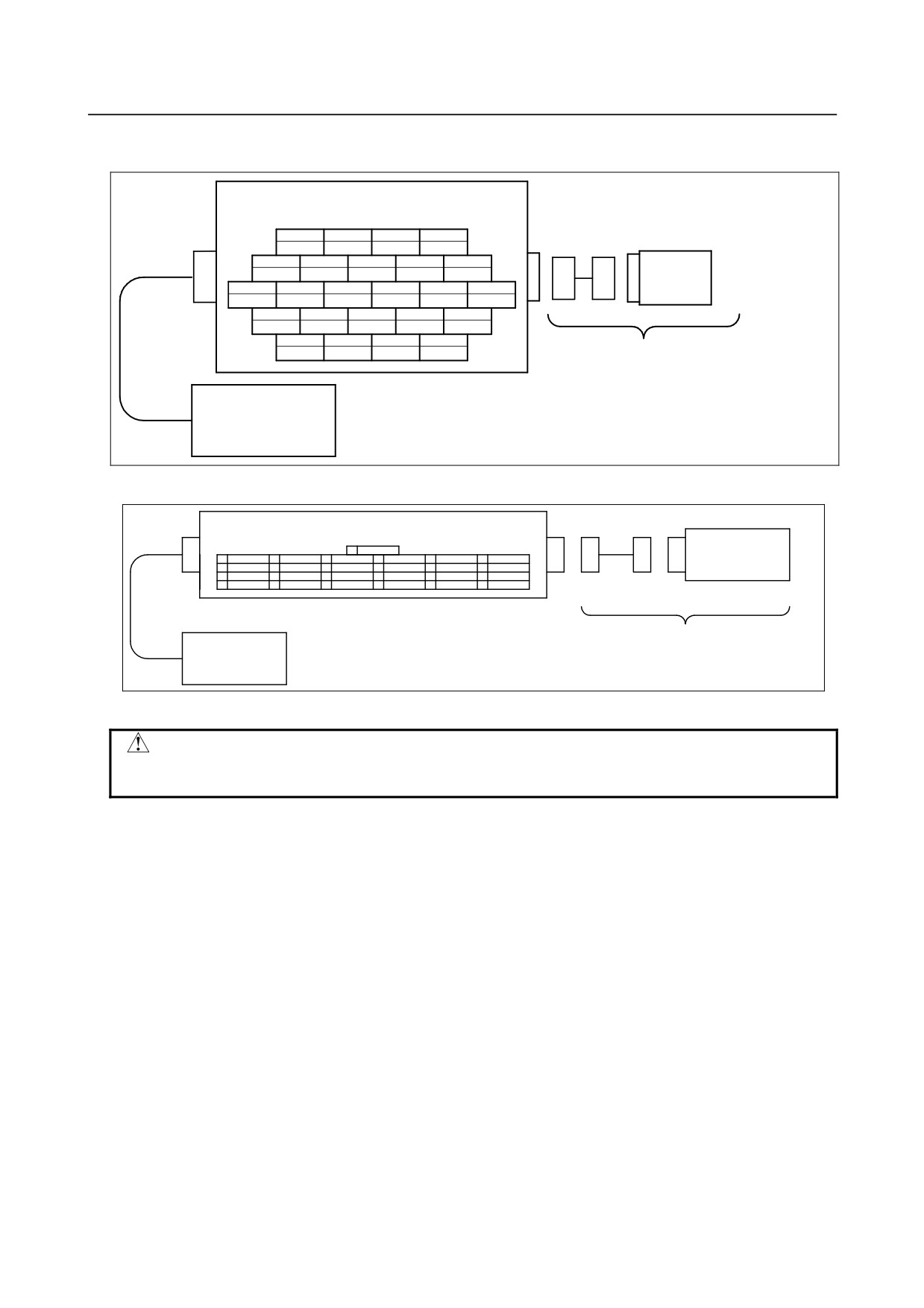
(1)
EE interface (RI/RO)(Option)
Fig. 5.3 (g) and (h) show the pin layout for the EE interface (RI/RO).
㪜㪜㩷㫀㫅㫋㪼㫉㪽㪸㪺㪼㩷㩿㪩㪠㪆㪩㪦㪀㩷㩿㪦㫌㫋㫇㫌㫋㪀
㪮㪉㪌㪉㪋㪝㩿㪝㫌㫁㫀㫂㫌㫉㪸㪅㪣㫋㪻㪀
4
3
2
1
RO4
RO3
RO2
RO1
9
8
7
6
5
RI1
0V(A1)
XHBK
RO6
RO5
㪜㫅㪻
15
14
13
12
11
10
㪼㪽㪽㪼㪺㫋㫆㫉
RI5
XPPABN
RI8
RI4
RI3
RI2
20
19
18
17
16
24VF(A1)
24VF(A1)
24VF(A1)
24VF(A1)
RI6
24
23
22
21
RI7
0V(A2)
RO8
RO7
㪧㫃㪼㪸㫊㪼㩷㫇㫉㪼㫇㪸㫉㪼㩷㪹㫐㩷㫌㫊㪼㫉㪅
㪯㪟㪙㪢㩷㪑㩷㪟㪸㫅㪻㩷㪹㫉㫆㫂㪼㫅
㪚㫆㫅㫋㫉㫆㫃㫃㪼㫉
㪯㪧㪧㪘㪙㪥㩷㪑㩷㪧㫅㪼㫌㫄㪸㫋㫀㪺㩷㫇㫉㪼㫊㫊㫌㫉㪼㩷㪸㪹㫅㫆㫉㫄㪸㫃
Fig. 5.3 (g) Pin layout for EE interface (RI/RO) (option)
㪜㪜㩷㫀㫅㫋㪼㫉㪽㪸㪺㪼㩷㩿㪩㪠㪆㪩㪦㪀㩷㩿㪦㫌㫋㫇㫌㫋㪀
Han24DD(HARTING)
G
㪜㫅㪻
21
RO7
17
24VF(A1)
13
RI8
9
RI1
5
RO5
1
RO1
22
RO8
18
24VF(A2)
14
XPPABN
10
RI2
6
RO6
2
RO2
㪼㪽㪽㪼㪺㫋㫆㫉
23
0V(A2)
19
24VF(A3)
15
RI5
11
RI3
7
XHBK
3
RO3
24
RI7
20
24VF(A4)
16
RI6
12
RI4
8
0V(A1)
4
RO4
㪯㪟㪙㪢㩷㪑㩷㪟㪸㫅㪻㩷㪹㫉㫆㫂㪼㫅
㪧㫃㪼㪸㫊㪼㩷㫇㫉㪼㫇㪸㫉㪼㩷㪹㫐㩷㫌㫊㪼㫉㪅
㪯㪧㪧㪘㪙㪥㩷㪑㩷㪧㫅㪼㫌㫄㪸㫋㫀㪺㩷㫇㫉㪼㫊㫊㫌㫉㪼㩷㪸㪹㫅㫆㫉㫄㪸㫃
㪚㫆㫅㫋㫉㫆㫃㫃㪼㫉
Fig. 5.3 (h) Pin layout for EE interface (RI/RO) (Severe dust/liquid protection package)
CAUTION
For wiring of the peripheral device to the EE interface, refer to the Chapter 4 of
CONNECTION section of CONTROLLER MAINTENANCE MANUAL, too.
- 56 -
B-82274EN/09
5.PIPING AND WIRING TO THE END EFFECTOR
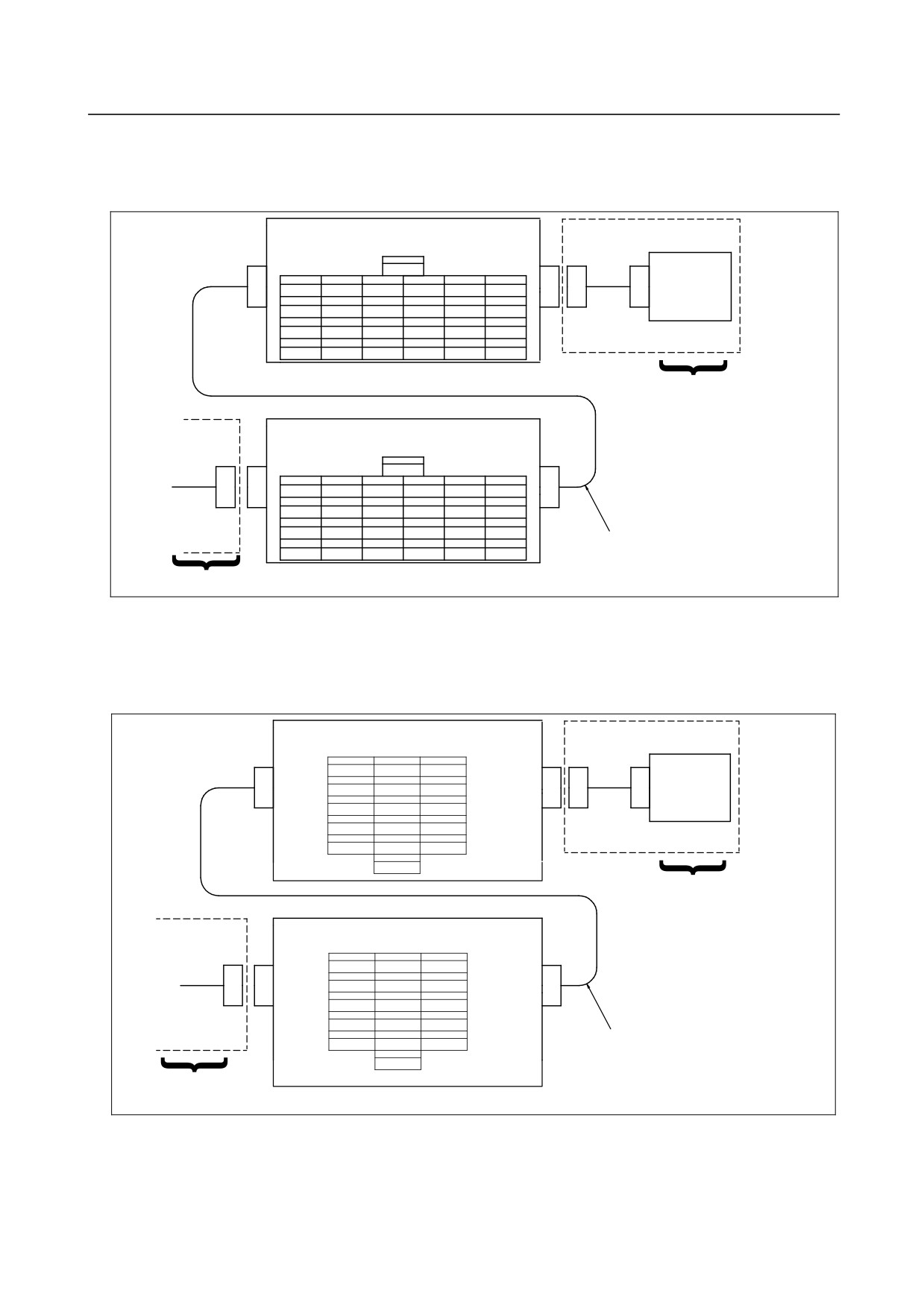
(2) User cable (signal line) ,user cable (signal line usable to the 3DL sensor and force sensor) Interface
(option)
Fig. 5.3 (i) shows pin layout for user cable (signal line) and user cable (signal line usable to the 3DL
sensor and force sensor) interface
㪬㫊㪼㫉㩷㪺㪸㪹㫃㪼㩷㩿㫊㫀㪾㫅㪸㫃㪀㩷㫀㫅㫋㪼㫉㪽㪸㪺㪼㩷㩿㪦㫌㫋㫇㫌㫋㩷㫊㫀㪻㪼㪀
F TYPE Han 24DD(HARTING)
G
21
17
13
9
5
1
㪜㫅㪻
S21
S17
S13
S9
S5
S1
㪜㪽㪽㪼㪺㫋㫆㫉
22
18
14
10
6
2
S22
S18
S14
S10
S6
S2
23
19
15
11
7
3
S23
S19
S15
S11
S7
S3
24
20
16
12
8
4
S24
S20
S16
S12
S8
S4
㪧㫃㪼㪸㫊㪼㩷㫇㫉㪼㫇㪸㫉㪼㩷㪹㫐㩷㪺㫌㫊㫋㫆㫄㪼㫉㪅
㪬㫊㪼㫉㩷㪺㪸㪹㫃㪼㩷㩿㫊㫀㪾㫅㪸㫃㪀㩷㫀㫅㫋㪼㫉㪽㪸㪺㪼㩷㩿㪠㫅㫇㫌㫋㩷㫊㫀㪻㪼㪀
M TYPE Han 24DD(HARTING)
G
1
5
9
13
17
21
S1
S5
S9
S13
S17
S21
2
6
10
14
18
22
S2
S6
S10
S14
S18
S22
3
7
11
15
19
23
S3
S7
S11
S15
S19
S23
2
4
8
12
16
20
24
㪇㪅㪉㫄㫄㬍㪉㪋㫇㪺㫊
S4
S8
S12
S16
S20
S24
㪧㫃㪼㪸㫊㪼㩷㫇㫉㪼㫇㪸㫉㪼㩷㪹㫐㩷㪺㫌㫊㫋㫆㫄㪼㫉㪅
Fig. 5.3 (i) Pin layout for user cable (signal line) user cable (signal line usable to the 3DL sensor and force
sensor) interface (option)
(3) User cable (power line) Interface (option)
Fig. 5.3 (j) shows pin layout for user cable (power line) interface.
㪬㫊㪼㫉㩷㪺㪸㪹㫃㪼㩷㩿㫇㫆㫎㪼㫉㪀㩷㫀㫅㫋㪼㫉㪽㪸㪺㪼㩷㩿㪦㫌㫋㫇㫌㫋㩷㫊㫀㪻㪼㪀
F TYPE Han 15D(HARTING)
C1
B1
A1
P6
P1
C2
B2
A2
㪜㫅㪻
P7
P2
㪜㪽㪽㪼㪺㫋㫆㫉
C3
B3
A3
P8
P3
C4
B4
A4
P9
P4
C5
B5
A5
P10
P5
G
G
㪧㫃㪼㪸㫊㪼㩷㫇㫉㪼㫇㪸㫉㪼㩷㪹㫐㩷㪺㫌㫊㫋㫆㫄㪼㫉㪅
㪬㫊㪼㫉㩷㪺㪸㪹㫃㪼㩷㩿㫇㫆㫎㪼㫉㪀㩷㫀㫅㫋㪼㫉㪽㪸㪺㪼㩷㩿㪠㫅㫇㫌㫋㩷㫊㫀㪻㪼㪀
M TYPE Han 15D(HARTING)
A1
B1
C1
P1
P6
A2
B2
C2
P2
P7
A3
B3
C3
P3
P8
A4
B4
C4
P4
P9
2
A5
B5
C5
㪈㪅㪉㪌㫄㫄㬍㪈㪇㫇㪺㫊
P5
P10
G
G
㪧㫃㪼㪸㫊㪼㩷㫇㫉㪼㫇㪸㫉㪼㩷㪹㫐㩷㪺㫌㫊㫋㫆㫄㪼㫉㪅
Fig. 5.3 (j) Pin layout for user cable (power line) interface (option)
- 57 -
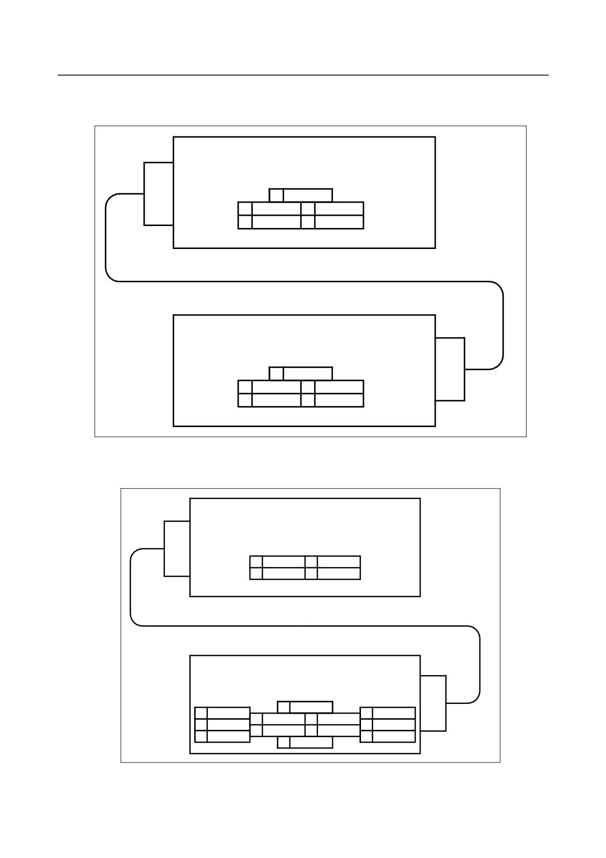
5.PIPING AND WIRING TO THE END EFFECTOR
B-82274EN/09
(4) DeviceNet cable (power line) Interface (option)
Fig. 5.3 (k) shows pin layout for DeviceNet cable (signal line) interface.
㪛㪼㫍㫀㪺㪼㪥㪼㫋㩷㪺㪸㪹㫃㪼㩷㩿㫊㫀㪾㫅㪸㫃㪀㩷㫀㫅㫋㪼㫉㪽㪸㪺㪼㩷㩿㪦㫌㫋㫇㫌㫋㪀
㪌㪧㪠㪥㩷㪝㪜㪤㪘㪣㪜㩷㪩㪜㪚㪜㪧㪫㪘㪚㪣㪜㩷䋨㪝㫌㫁㫀㫂㫌㫉㪸㪅㪣㫋㪻䋩
3
V-
2
V+
4
CAN H
1
㪛㪩㪘㪠㪥㩷㪮㪠㪩㪜
5
CAN L
㪛㪼㫍㫀㪺㪼㪥㪼㫋㩷㪺㪸㪹㫃㪼㩷㩿㫊㫀㪾㫅㪸㫃㪀㩷㫀㫅㫋㪼㫉㪽㪸㪺㪼㩷㩿㪠㫅㫇㫌㫋㪀
㪌㪧㪠㪥㩷㪤㪘㪣㪜㩷㪩㪜㪚㪜㪧㪫㪘㪚㪣㪜㩷䋨㪝㫌㫁㫀㫂㫌㫉㪸㪅㪣㫋㪻䋩
3
V-
2
V+
4
CAN H
1
㪛㪩㪘㪠㪥㩷㪮㪠㪩㪜
5
CAN L
Fig. 5.3 (k) Pin layout for DeviceNet cable (signal line) interface (option)
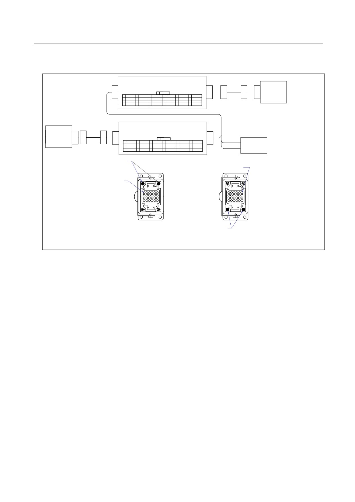
(5) DeviceNet cable (power line) Interface (option)
Fig. 5.3 (l) shows pin layout for DeviceNet cable (power line) interface.
㪛㪼㫍㫀㪺㪼㪥㪼㫋㩷㪺㪸㪹㫃㪼㩷㩿㫇㫆㫎㪼㫉㪀㩷㫀㫅㫋㪼㫉㪽㪸㪺㪼㩷㩿㪦㫌㫋㫇㫌㫋㪀
㪌㪧㪠㪥㩷㪝㪜㪤㪘㪣㪜㩷㪩㪜㪚㪜㪧㪫㪘㪚㪣㪜㩷䋨㪝㫌㫁㫀㫂㫌㫉㪸㪅㪣㫋㪻䋩
2
COM
3
OUTP
1
COM
4
NM
㪛㪼㫍㫀㪺㪼㪥㪼㫋㩷㪺㪸㪹㫃㪼㩷㩿㫇㫆㫎㪼㫉㪀㩷㫀㫅㫋㪼㫉㪽㪸㪺㪼㩷㩿㪠㫅㫇㫌㫋㪀
㪤㩷㪫㪰㪧㪜㩷㪟㪸㫅㩷㪈㪇㪜㪜㩷䋨㪟㪸㫉㫋㫀㫅㪾䋩
G
1
NM
8
4
COM
6
2
OUTP
9
5
7
3
COM
10
G
Fig. 5.3 (l) Pin layout for DeviceNet cable (power line) interface (option)
- 58 -
B-82274EN/09
5.PIPING AND WIRING TO THE END EFFECTOR
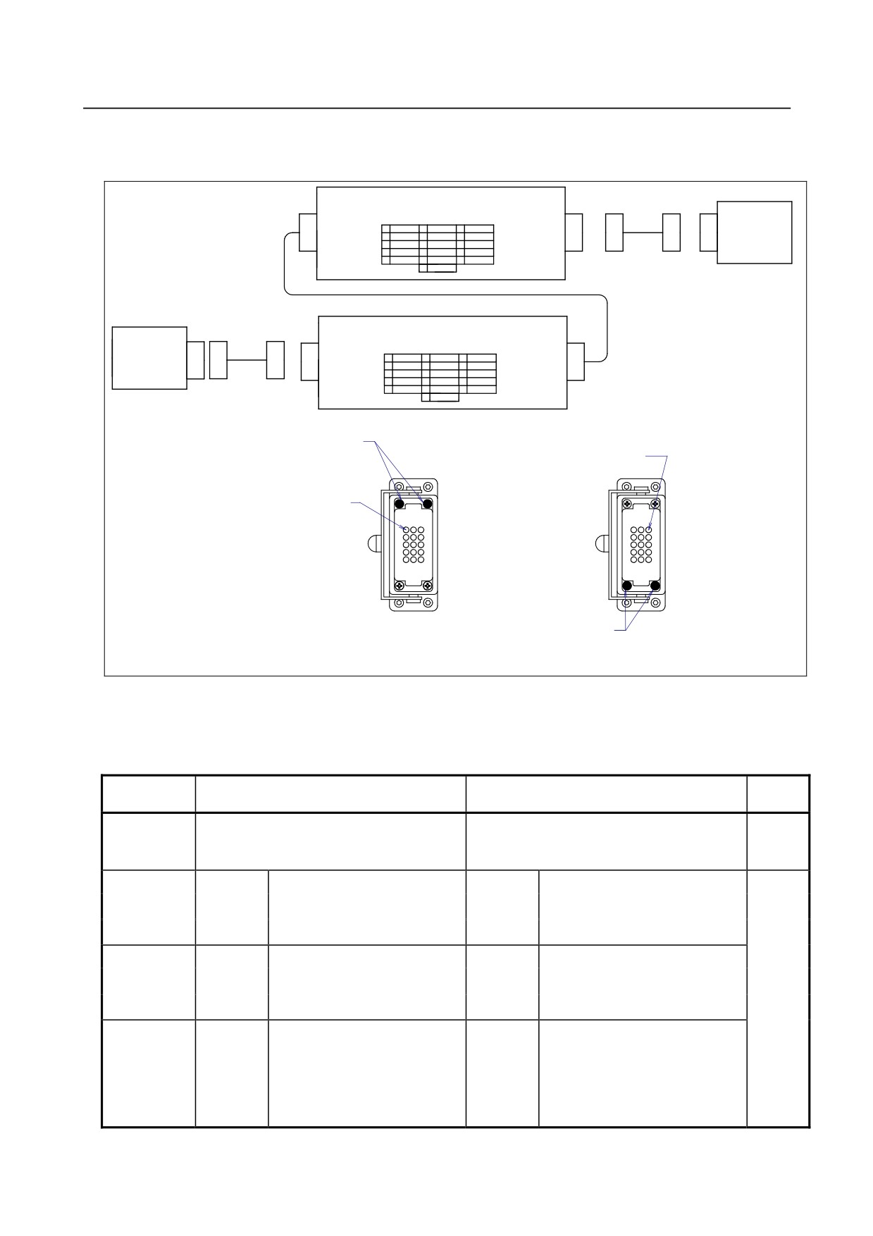
(6) Additional axis motor cable (Pulsecoder line) Interface (option)
Fig. 5.3 (m) shows pin layout for Additional axis motor cable (Pulsecoder line) interface.
The connector has a code pin for preventing improper insertion.
㪘㪻㪻㫀㫋㫀㫆㫅㪸㫃㩷㪸㫏㫀㫊㩷㫄㫆㫋㫆㫉㩷㪺㪸㪹㫃㪼㩷㩿㪧㫌㫃㫊㪼㪺㫆㪻㪼㫉㪀㩷㫀㫅㫋㪼㫉㪽㪸㪺㪼㩷㩿㫆㫌㫋㫃㪼㫋㪀
FEMALE TYPE Han24DD (HARTING)
㪘㪻㪻㫀㫋㫀㫆㫅㪸㫃
G 㪞
21
17
13
9
㪌㪭㩿㪡㪎㪘㪈㪀
5
㩷㪇㪭㩿㪡㪎㪘㪈㪀
1
㪪㪧㪛㪡㪎
㪸㫏㫀㫊㩷㫄㫆㫋㫆㫉
22
18
14
10
㪌㪭㩿㪡㪎㪘㪉㪀
6
㩷㪇㪭㩿㪡㪎㪘㪉㪀
2
㪯㪪㪧㪛㪡㪎
23
19
15
11
7
3
㪧㪩㪨㪡㪎
24
20
16
12
㪍㪭㩿㪙㪫㪎㪀
8
㩷㪇㪭㩿㪙㪫㪎㪀
4
㪯㪧㪩㪨㪡㪎
㪘㪻㪻㫀㫋㫀㫆㫅㪸㫃㩷㪸㫏㫀㫊㩷㫄㫆㫋㫆㫉㩷㪺㪸㪹㫃㪼㩷㩿㪧㫌㫃㫊㪼㪺㫆㪻㪼㫉㪀㩷㫀㫅㫋㪼㫉㪽㪸㪺㪼㩷㩿㫀㫅㫃㪼㫋㪀
MALE TYPE Han24DD (HARTING)
㪚㫆㫅㫋㫉㫆㫃㫃㪼㫉
G 㪞
1
㪪㪧㪛㪡㪎
5
㩷㪇㪭㩿㪡㪎㪘㪈㪀
9
㪌㪭㩿㪡㪎㪘㪈㪀
13
17
21
㩷㪍㪭㩿㪙㪫㪎㪀
2
㪯㪪㪧㪛㪡㪎
6
㩷㪇㪭㩿㪡㪎㪘㪉㪀
10
㪌㪭㩿㪡㪎㪘㪉㪀
14
18
22
㪙㪸㫋㫋㪼㫉㫐
3
㪧㪩㪨㪡㪎
7
11
15
19
23
㩷㪇㪭㩿㪙㪫㪎㪀
㪹㫆㫏
4
㪯㪧㪩㪨㪡㪎
8
12
16
20
24
㪚㫆㪻㪼㩷㫇㫀㫅
㪥㫆㪅㪈㩷㫇㫀㫅
㪥㫆㪅㪈㩷㫇㫀㫅
㪚㫆㪻㪼㩷㫇㫀㫅
㪘㪻㪻㫀㫋㫀㫆㫅㪸㫃㩷㪸㫏㫀㫊㩷㫄㫆㫋㫆㫉㩷㪺㪸㪹㫃㪼㩷㩿㪧㫌㫃㫊㪼㪺㫆㪻㪼㫉㪀
㪘㪻㪻㫀㫋㫀㫆㫅㪸㫃㩷㪸㫏㫀㫊㩷㫄㫆㫋㫆㫉㩷㪺㪸㪹㫃㪼㩷㩿㪧㫌㫃㫊㪼㪺㫆㪻㪼㫉㪀
㫀㫅㫋㪼㫉㪽㪸㪺㪼㩷㪺㫆㪻㪼㩷㫇㫀㫅㩷㫇㫆㫊㫀㫀㫋㫆㫅㩷㩿㫀㫅㫃㪼㫋㪀
㫀㫅㫋㪼㫉㪽㪸㪺㪼㩷㪺㫆㪻㪼㩷㫇㫀㫅㩷㫇㫆㫊㫀㫀㫋㫆㫅㩷㩿㫆㫌㫋㫃㪼㫋㪀
Fig. 5.3 (m) Pin layout for additional axis motor cable (Pulsecoder line) interface (option)
- 59 -
5.PIPING AND WIRING TO THE END EFFECTOR
B-82274EN/09
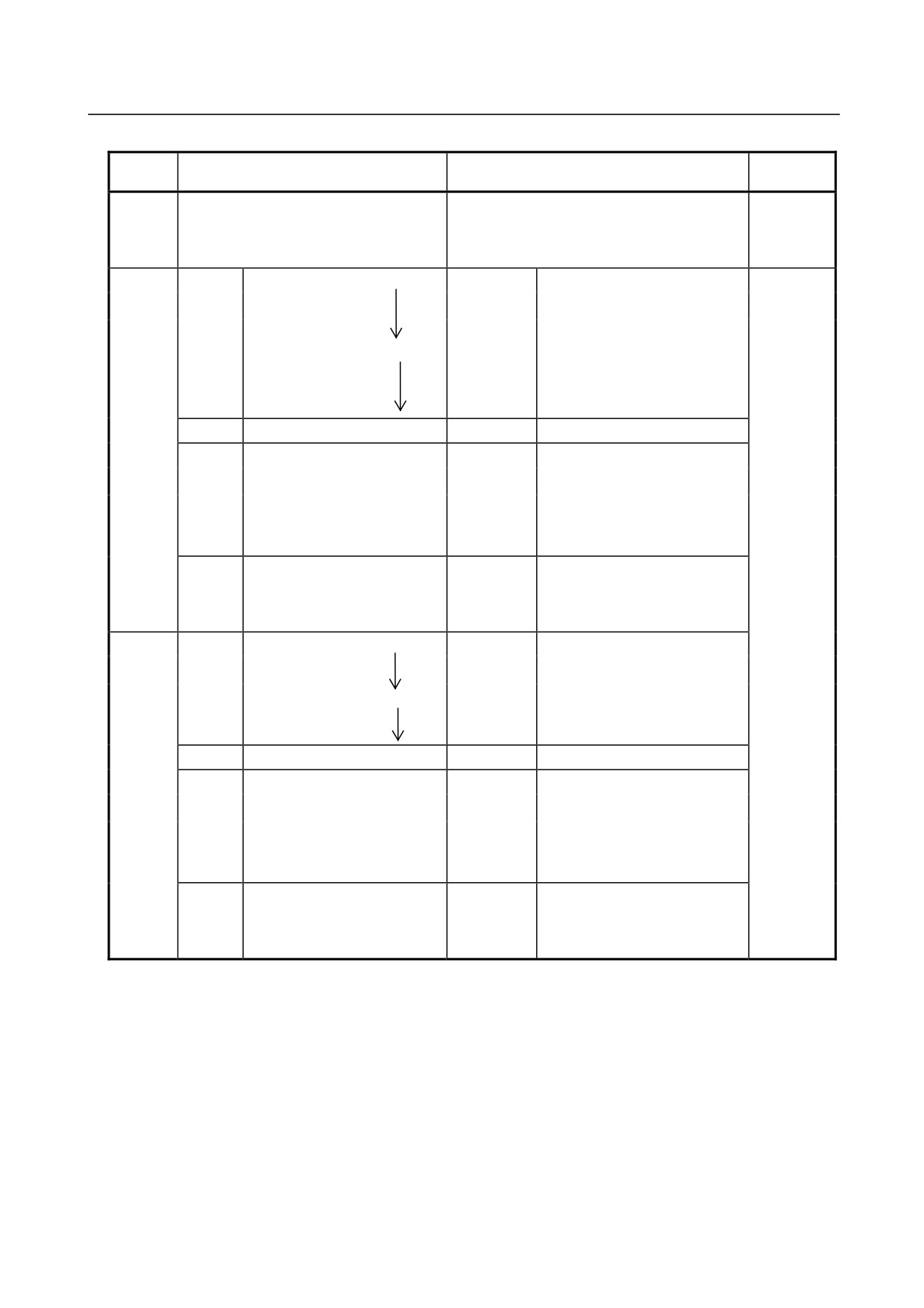
(7) Additional axis motor cable (power and brake cables) Interface (option) Fig. 5.3 (n) shows pin
layout for Additional axis motor cable (power and brake cables) interface.
The connector has a code pin for preventing improper insertion.
㪘㪻㪻㫀㫋㫀㫆㫅㪸㫃㩷㪸㫏㫀㫊㩷㫄㫆㫋㫆㫉㩷㪺㪸㪹㫃㪼㩷㩿㫇㫆㫎㪼㫉㪃㪹㫉㪸㫂㪼㪀㩷㫀㫅㫋㪼㫉㪽㪸㪺㪼㩷㩿㫆㫌㫋㫃㪼㫋㪀
FEMALE TYPE Han15D (HARTING)
㪚㪈
㪙㪈
㪙㪢㩿㪡㪎㪀
㪘㪈
㪡㪎㪬㪈
㪘㪻㪻㫀㫋㫀㫆㫅㪸㫃
㪚㪉
㪙㪉
㪙㪢㪚㩿㪡㪎㪀
㪘㪉
㪡㪎㪭㪈
㪚㪊
㪙㪊
㪘㪊
㪡㪎㪮㪈
㪸㫏㫀㫊㫄㫆㫋㫆㫉
㪚㪋
㪙㪋
㪘㪋
㪡㪎㪞㪈
㪚㪌
㪙㪌
㪘㪌
G 㪞
㪘㪻㪻㫀㫋㫀㫆㫅㪸㫃㩷㪸㫏㫀㫊㩷㫄㫆㫋㫆㫉㩷㪺㪸㪹㫃㪼㩷㩿㫇㫆㫎㪼㫉㪃㪹㫉㪸㫂㪼㪀㩷㫀㫅㫋㪼㫉㪽㪸㪺㪼㩷㩿㫀㫅㫃㪼㫋㪀
MALE TYPE Han15D (HARTING)
㪚㫆㫅㫋㫉㫆㫃㫃㪼㫉
㪘㪈
㪡㪎㪬㪈 㪙㪈
㪙㪢㩿㪡㪎㪀
㪚㪈
㪘㪉
㪡㪎㪭㪈
㪙㪉
㪙㪢㪚㩿㪡㪎㪀
㪚㪉
㪘㪊
㪡㪎㪮㪈
㪙㪊
㪚㪊
㪘㪋
㪡㪎㪞㪈
㪙㪋
㪚㪋
㪘㪌
㪙㪌
㪚㪌
G 㪞
㪚㫆㪻㪼㩷㫇㫀㫅
㪘㪈㩷㫇㫀㫅
㪘㪈㩷㫇㫀㫅
㪚㫆㪻㪼㩷㫇㫀㫅
㪘㪻㪻㫀㫋㫀㫆㫅㪸㫃㩷㪸㫏㫀㫊㩷㫄㫆㫋㫆㫉㩷㪺㪸㪹㫃㪼㩷㩿㫇㫆㫎㪼㫉㪃㪹㫉㪸㫂㪼㪀
㪘㪻㪻㫀㫋㫀㫆㫅㪸㫃㩷㪸㫏㫀㫊㩷㫄㫆㫋㫆㫉㩷㪺㪸㪹㫃㪼㩷㩿㫇㫆㫎㪼㫉㪃㪹㫉㪸㫂㪼㪀
㫀㫅㫋㪼㫉㪽㪸㪺㪼㩷㪺㫆㪻㪼㩷㫇㫀㫅㩷㫇㫆㫊㫀㫀㫋㫆㫅㩷㩿㫀㫅㫃㪼㫋㪀
㫀㫅㫋㪼㫉㪽㪸㪺㪼㩷㪺㫆㪻㪼㩷㫇㫀㫅㩷㫇㫆㫊㫀㫀㫋㫆㫅㩷㩿㫆㫌㫋㫃㪼㫋㪀
Fig. 5.3 (n) Pin layout for additional axis motor cable (power and brake cables)) interface (option)
Connector specifications
Table 5.3 (a) Connector specifications (Mechanical unit side)
Maker
Cable
Input side (J1 base)
Output side (J3 casing)
/Dealer
EE
Fujikura
───
JMWR25.34F
(RI/RO)
.Ltd
Housing
09 30 006 0301
Housing
09 30 006 0301
Insert
09 16 024 3001 (Han 24DD M)
Insert
09 16 024 3101 (Han 24DD F)
AS
Contact
09 15 000 6103
Contact
09 15 000 6203
Housing
09 20 010 0301
Housing
09 20 010 0301
Insert
09 21 015 3001 (Han 15D M)
Insert
09 21 015 3101 (Han 15D F)
AP
Contact
09 15 000 6103
Contact
09 15 000 6203
HARTING
K.K
EE(RI/RO)
Housing
Housing
09 30 006 0301
(Cable
Insert
Insert
09 16 024 3101 (Han 24DD F)
corresponds
Contact
Contact
09 15 000 6204
───
to the severe
Guide pin
Guide pin
09 30 000 9908
dust/liquid
protection)
- 60 -
B-82274EN/09
5.PIPING AND WIRING TO THE END EFFECTOR
Table 5.3 (b) Connector specifications (User side)
Maker
Cable
Input side (J1 base)
Output side (J3 casing)
/Dealer
JMSP25.34M
Straight (Appendix)
EE
(FANUC specification:
Fujikura
.Lt
───
(RI/RO)
A63L-0001-0234#S25.34M)
d
JMLP25.34M Angle
09 30 006 1540 Side entry
1541
Hood
0542
0543
Select
Hood
←The same
1440 Top entry
one
1441
0442
0443
Insert
09 16 024 3101 (Han 24DD F)
Insert
09 16 024 3001 (Han 24DD M)
AS
09 15 000 6204 AWG 26-22
09 15 000 6104 AWG 26-22
Contact
6203 AWG 20
6103 AWG 20
6205 AWG 18
6105 AWG 18
Contact
Select
6202 AWG 18
6102 AWG 18
one
6201 AWG 16
6101 AWG 16
6206 AWG 14
6106 AWG 14
09 00 000 5083
Clamp
5086
Select
Clamp
←The same
5090
HARTING
one
5094 etc.
K.K
09 30 006 1541 Side entry
Hood
0540
0541
Select
Hood
←The same
1440 Top entry
one
0440
0441
Insert
09 21 015 3101 (Han 15D F)
Insert
09 21 015 3001 (Han 15D M)
09 15 000 6204 AWG 26-22
09 15 000 6104 AWG 26-22
AP
Contact
6203 AWG 20
6103 AWG 20
6205 AWG 18
6105 AWG 18
Contact
Select
6202 AWG 18
6102 AWG 18
one
6201 AWG 16
6101 AWG 16
6206 AWG 14
6106 AWG 14
09 00 000 5083
Clamp
5086
Select
Clamp
←The same
5090
one
5094 etc.
- 61 -
5.PIPING AND WIRING TO THE END EFFECTOR
B-82274EN/09
Maker
Cable
Input side (J1 base)
Output side (J3 casing)
/Dealer
09 30 006 1440
(FANUC specification :
Hood
A63L-0001-0453#06B1440)
EE
(RI/RO)
09 16 024 3001 (Han 24DD M)
(These
Insert
(FANUC specification :
are
A63L-0001-0453#24DDM)
attached
09 15 000 6104 AWG 26-22
to the
(FANUC specification :
cables
A63L-0001-0453#CA6140)
HARTING
which are
───
6103 AWG 20
Contact
K.K
correspon
6105 AWG 18
ded to the
6102 AWG 18
sever
6101 AWG 16
dust/liquid
6106 AWG 14
protection.
15.3D
)
Clamp
(FANUC specification :
A63L-0001-0453#A-15.3D)
09 30 000 9909
Bush
(FANUC specification :
A63L-0001-0453#A-9909)
Table 5.3 (c) Connector specifications (DeviceNet cable, on the Mechanical unit side)
Maker
Cable
Input side (J1 base)
Manu.
Output side (J3 casing)
/Dealer
Fujikura
Fujikura
DS
CM03A-R5P-S-2
CM03A-R5P-S-2
Ltd
Ltd
09 30 006 0301
Housing
MOLEX
09 32 010 3001
HARTING
DP
Insert
84854-9102
JAPAN
09 33 000 6105
K.K.
Contact
CO.LTD
- 62 -
B-82274EN/09
5.PIPING AND WIRING TO THE END EFFECTOR
Table 5.3 (d) Connector specifications (DeviceNet cable, on the user equipment side)
Maker
Cable
Input side (J1 base)
Manu.
Output side (J3 casing)
/Dealer
MINI connector for use on the device net
Fujikura
Fujikura
DS
5-pin, female 1
CM03-J5P
.Ltd
Ltd
CM03-P5S
09 30 006 1540 Side entry
Hood
1541
0542
Select
0543
just
1440
Top entry
one
1441
0442
0443
Insert
09 32 010 3101
09 15 000 6204 AWG 26-22
HARTING
Fujikura
DP
Contact
CM03-J4P
6203 AWG 20
K.K.
Ltd
6205 AWG 18
Select
6202 AWG 18
just
6201 AWG 16
one
6206 AWG 14
Clamp
09 00 000 5083
5086
Select
5090
just
5094
one
Many other types are available
Table 5.3 (e) Connector specifications (Additional axis motor cable, on the Mechanical unit side)
Maker
Cable
Input side (J1 base)
Output side (J3 casing)
/Dealer
Housing
09 30 006 0301
Housing
09 30 006 0301
Insert
09 16 024 3001 (Han 24DD M)
Insert
09 16 024 3101 (Han 24DD F)
ARP
Contact
09 15 000 6103
Contact
09 15 000 6203
Code pin
09 30 000 9901
Code pin
09 30 000 9901
HARTING
K.K.
Housing
09 20 010 0301
Housing
09 20 010 0301
Insert
09 21 015 3001 (Han 15D M)
Insert
09 21 015 3101 (Han 15D F)
ARM
Contact
09 15 000 6101
Contact
09 15 000 6201
Code pin
09 30 000 9901
Code pin
09 30 000 9901
NOTE
For details, such as the dimensions, refer to the related catalogs offered by the
respective manufacturers, or contact FANUC.
- 63 -
6.AXIS LIMIT SETUP
B-82274EN/09
6 AXIS LIMIT SETUP
Each part of the mechanical unit is carefully adjusted at the factory before shipment. Therefore, it is
usually unnecessary for the customer to make adjustments at the time of delivery. However, after a long
period of use or after parts are replaced, adjustments may be required.
Axis limits define the motion range of the robot. The operating range of the
robot axes can be restricted because of:
• Work area limitations
• Tooling and fixture interference points
• Cable and hose lengths
There are three methods used to prevent the robot from going beyond the necessary motion range. These
are
• Axis limit software settings (All axes)
• Axis limit adjustable mechanical stopper ((J1, J2, J3 axis) option)
• Axis limit switches ((J1 axis) option)
CAUTION
1 Changing the motion range of any axis affects the operation range of the robot. To avoid
trouble, carefully consider a possible effect of the change to the movable range of each
axis in advance. Otherwise, it is likely that an unexpected condition occurs; for example,
an alarm may occur in a previous taught position.
2 For the J1axis, do not count merely on software-based limits to the movable range when
changing the movable range of the robot. Use mechanical stoppers together so that
damage to peripheral equipment and injuries to human bodies can be avoided. In this
case, make the software-specified limits match the limits based on the mechanical
stoppers.
3 Mechanical stoppers are physical obstacles. The robot cannot move beyond them. For
the J1 to J3 axis(except J2 and J3 of M-710iC/50S), it is possible to re-position the
mechanical stoppers. For J5 axes, the mechanical stoppers are fixed. For the J4 and J6
axes, only software-specified limits are available.
4 Adjustable mechanical stoppers are deformed in a collision to stop the robot. Once a
stopper is subject to a collision, it can no longer assure its original strength and,
therefore, may not stop the robot. When this happens, replace it with a new one.
6.1
SOFTWARE SETTING
Upper and lower axis limits about motion range can be changed by software settings. The limits can be
set for all axes. The robot stops the motion if the robot reaches to the limits.
Procedure
Setting Up Axis Limits
1.
Press MENUS.
2.
Select SYSTEM.
3.
Press F1, [TYPE].
4.
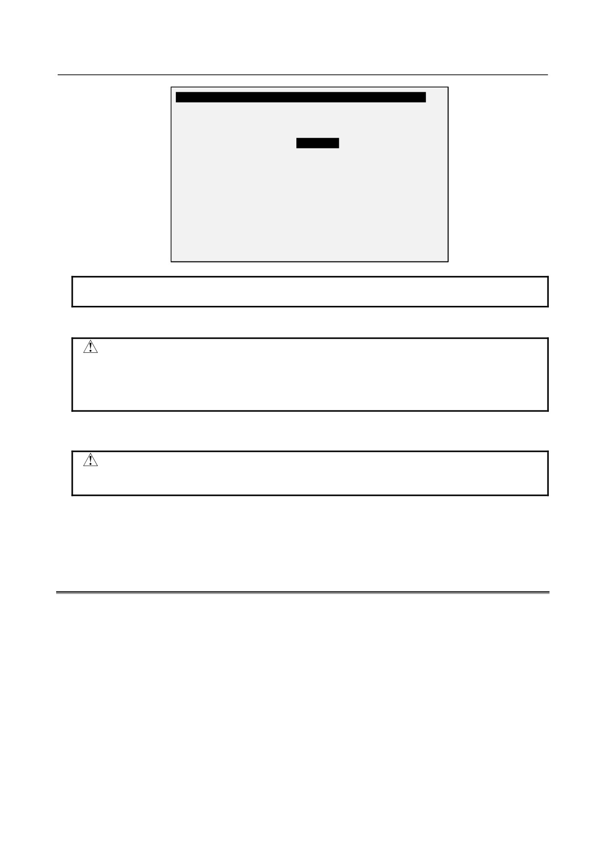
Select Axis Limits. You will see a screen similar to the following.
- 64 -
B-82274EN/09
6.AXIS LIMIT SETUP
System Axis Limits
JOINT
100%
1/16
AXIS
GROUP
LOWER
UPPER
1
1
-150.00
150.00
dg
2
1
-60.00
75.00
dg
3
1
-110.00
50.00
dg
4
1
-240.00
240.00
dg
5
1
-120.00
120.00
dg
6
1
-360.00
360 00
dg
7
0
0.00
0.00
mm
8
0
0.00
0.00
mm
9
0
0.00
0.00
mm
[ TYPE ]
NOTE
0 indicates the robot does not have these axes.
5
Move the cursor to the axis limit you want to set.
WARNING
Do not depend on J1, J2, and J3 axis (except J2 and J3 of M-710iC/50S)limit
software settings to control the motion range of your robot. Use the axis limit
switches or Mechanical stopper also; otherwise, injury to personnel or damage
to equipment could occur.
6
Type the new value using the numeric keys on the teach pendant.
7
Repeat Steps 5 through 6 until you are finished setting the axis limits.
WARNING
You must turn off the controller and then turn it back on to use the new
information; otherwise, injury to personnel or damage to equipment could occur.
8
Turn off the controller and then turn it back on again in the cold start mode so the new information
can be used.
6.2
ADJUSTABLE MECHANICAL STOPPER AND LIMIT
SWITCH SETTING (OPTION)
For the J1, J2, and J3 axes, Adjustable mechanical stopper (option) can be installed in addition to standard
mechanical stopper. It is possible to re-position adjustable mechanical stoppers. The limit switch-based
movable range can be changed by changing the dog positions.
Change the position of the mechanical stoppers according to the desired movable range.
- 65 -
6.AXIS LIMIT SETUP
B-82274EN/09
Table 6.2(a) motion range that can be set by the adjustable mechanical stopper and space between the upper
and lower limits
Item
Movable range
J1 axis adjustable
Upper limit
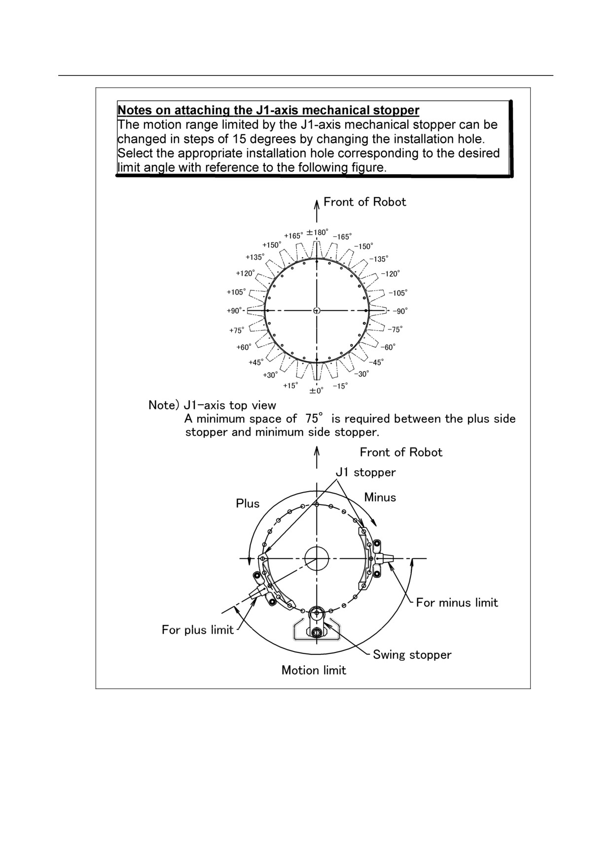
Settable in steps of 15° degrees in a range of -105°
mechanical stopper, limit
to +180° degrees
switch
Lower limit
Settable in steps of 15° degrees in the range of -180°
to +150° degrees
Space between
A space of 75° degrees or more is required.
the upper and
lower limits
J2 axis adjustable mechanical
Upper limit
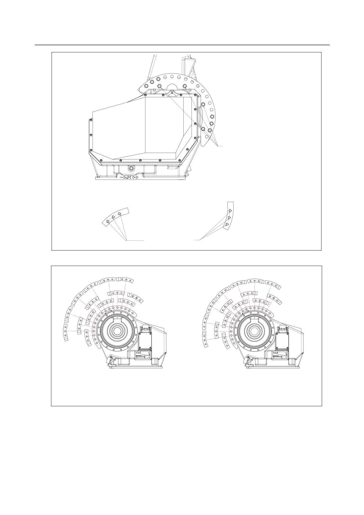
Settable in steps of 10° in the range of -50° to +80°. A
stopper (M-710iC/50,/70,
mechanical stopper is also provided at the upper limit
/50H ,/50E)
+140° of the standard movable range.
Lower limit
Settable in steps of 10° in the range of -60° to +80°. A
mechanical stopper is also provided at the lower limit
-95°of the standard movable range.
Space between the
A space of 50° degrees or more is required.
upper and lower
limits
J3 axis adjustable mechanical
Upper limit
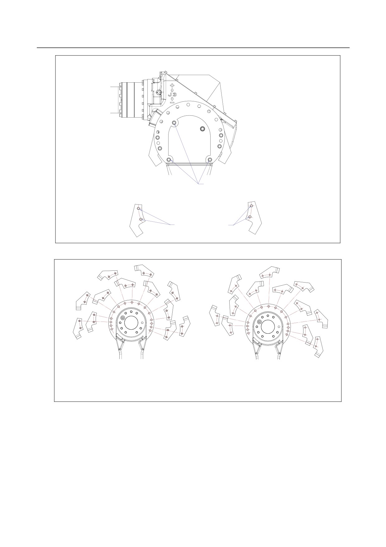
Settable in steps of 20° in the range of -20° to +160°
stopper (M-710iC/50,70,
and -30°and
+170°. A mechanical stopper is also
/50H,/50E)
provided at the upper limit +283.5° of the standard
movable range.
Lower limit
Settable in steps of 20° in the range of -40° to +140°
and -50°and
+150°. A mechanical stopper is also
provided at the lower limit -163.5° of the standard
movable range.
Space between the
A space of 60° degrees or more is required.
upper and lower
limits
NOTE
If the newly set operation range does not include 0°, it is necessary to change it
by zero position mastering so that 0° is included.
NOTE
When adjustable mechanical stopper is ordered, mounting bolt is attached.
NOTE
When motion range is changed by movable mechanical stopper, be sure to set
the motion range of soft same refer to Section 6.1
- 66 -
B-82274EN/09
6.AXIS LIMIT SETUP
Fig. 6.2(a) Mechanical stopper and motion limit of J1-axis (Option)
- 67 -
6.AXIS LIMIT SETUP
B-82274EN/09
Attach bolt M12X25(pcs)
and washer to these four holes.
Attach bolt M12X35(3pcs)
and washer to thes three taps.
Fig. 6.2(b) J2-Axis movable mechanical stopper (M-710iC/50, /70, /50H ,/50E)
-10°
-30°
-30°
-10°
-50°
+10°
-20°
+10°
-20°
+30°
-50°
-60°
+20°
0°
-40°
+30°
0°
+20°
-40°
+50°
+40°
+40°
+50°
+60°
+60°
+70°
+80°
+70°
+80°
PLUS SIDE STOPPER SETTING
MINUS SIDE STOPPER SETTING
(Note) J2-axis left view
A minimum space of 50°is required between the plus side stopper and the minus side
stopper
Fig. 6.2(c) Attachment of J2-Axis movable mechanical stopper (M-710iC/50, /70, /50H ,/50E)
- 68 -
B-82274EN/09
6.AXIS LIMIT SETUP
Attach bolt M12X35(3pcs) and washer
to these three holes.
Attach bolt M12X65(2pcs) and
washer to these taps.
Fig. 6.2(d) J3-Axis movable mechanical stopper (M-710iC/50, /70, /50H ,/50E)
+100°
+60°
+60°
+100°
+20°
+80°
+20°
+140°
+40°
+40°
+80°
+120°
0°
+120°
0°
+160°
+140°
-20°
+170°
-20°
+150°
-40°
-30°
-50°
PLUS SIDE STOPPER SETTING
MINUS SIDE STOPPER SETTING
(Note) J3-axis left view
A minimum space of 60°is required between the plus side stopper and the minus side
stopper
Fig. 6.2(e) Attachment of J3-Axis movable mechanical stopper (M-710iC/50, /70, /50H ,/50E)
- 69 -
6.AXIS LIMIT SETUP
B-82274EN/09
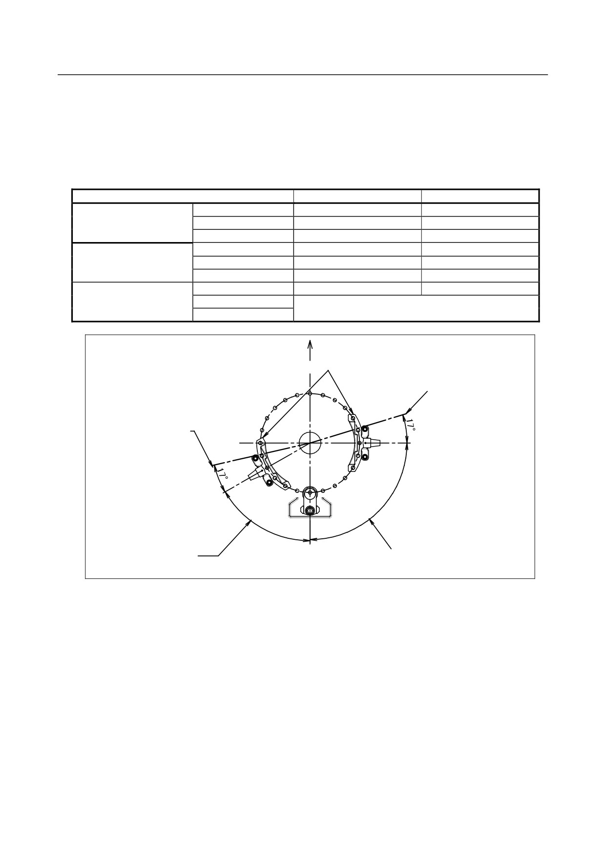
The movable mechanical stopper is a mechanism that can be adjusted in its position. The robot can
work safely inside the adjusted motion range, up to the maximum range as shown in Table 6.2 (b)
A robot attempting to travel beyond this set range of motion, will be stopped by these stoppers, by
collision; and therefore the robot will remain contained within the setup range .
Stopping the robot will cause the mechanical stopper to be “transformed” (means : permanently
damaged). Be sure to exchange such “transformed” stopper.
Table 6.2(b) The maximum stopping distance(position ) of movable mechanical stopper
Item
Plus side
Minus side
M-710iC/50, /50H, /50E
J1
+17°
-17°
J2
+19°
-18°
J3
+11°
-10°
M-710iC/70
J1
+16°
+16°
J2
+12°
-11°
J3
+11°
-10°
M-710iC/50S
J1
+17°
-17°
J2
There is no movable mechanical stopper.
J3
Front of robot
J1 movable stopper
The maximum stoppin
distance (position)
The maximum stopping
distance
(position)
Specified motion range
Specified motion range
of minus side
of plus side
Fig. 6.2(f) The maximum stopping distance of movable mechanical stopper
(J1-axis of M-710iC/50, /50H , /50S, /50E)
- 70 -