FANUC Robot M-710iC MECHANICAL UNIT. OPERATOR'S MANUAL (B-82274EN/09) - page 2
B-82274EN/09
1.TRANSPORTATION AND INSTALLATION
1.3
MAINTENANCE AREA
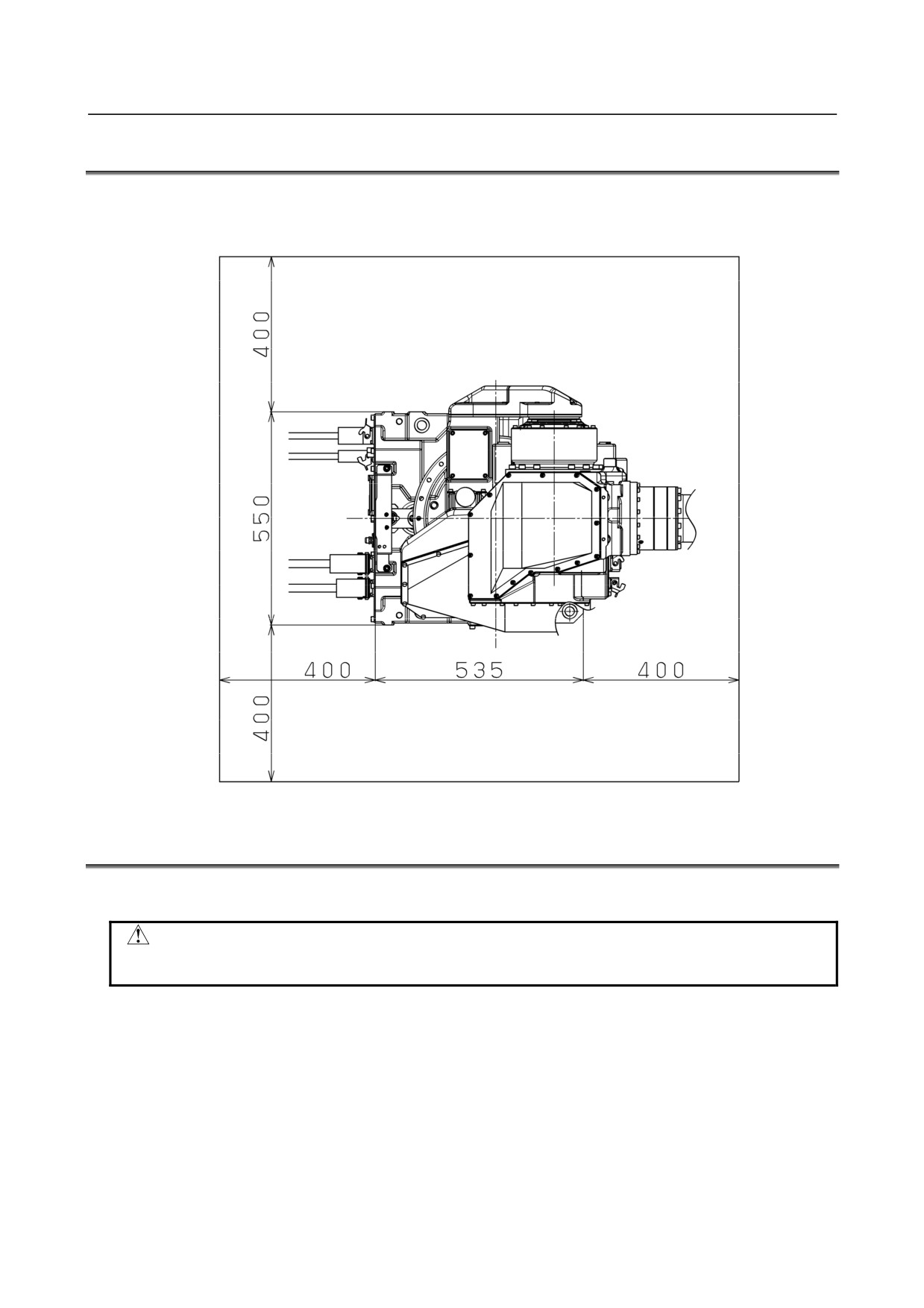
Fig. 1.3 shows the maintenance area of the mechanical unit. Be sure to leave enough room for the robot to
be mastered.
See Chapter 8 for the mastering.
Fig. 1.3 Maintenance area
1.4
INSTALLATION SPECIFICATIONS
See Section 3.1 and caution below about robot installation specifications.
CAUTION
The wound of coating of robot connection cable causes the flood. Please note handling
enough when setting it up, and exchange it when damaging.
- 9 -
2.CONNECTION WITH THE CONTROLLER
B-82274EN/09
2 CONNECTION WITH THE CONTROLLER
2.1
CONNECTION WITH THE CONTROLLER
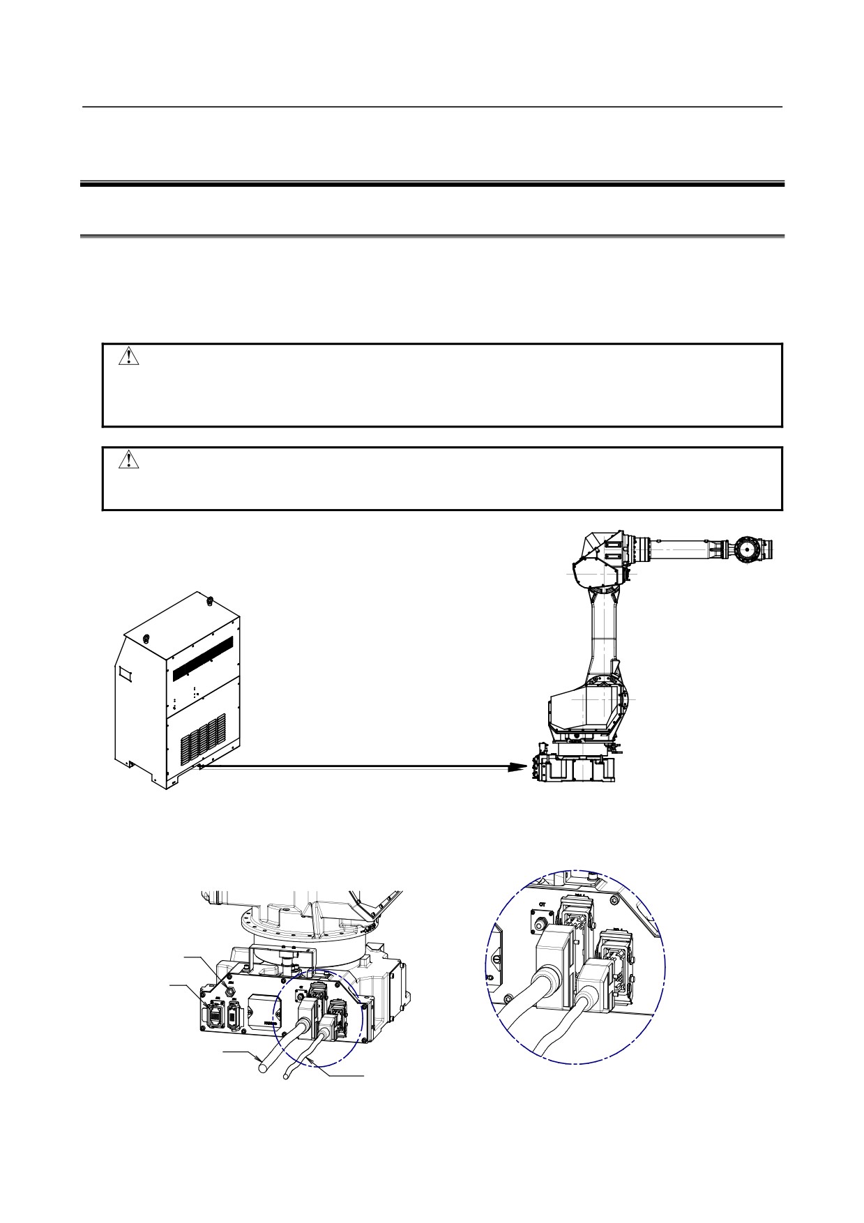
The robot is connected with the controller (NC) via the power cable and signal cable. Connect these
cables to the connectors on the back of the base.
For details on air and option cables, see Chapter 5.
CAUTION
1 Before connecting the cables, be sure to turn off the controller power.
2 Don’t use 10m or longer coiled cable without untying. The long coiled cable will
heat and damage itself.
WARNING
Before turning on controller power, be sure to connect robot and controller with
the earth line. Otherwise, there is the risk of electrical shock.
Robot
Controller
Power and Signal cables
earth cables
Air
Option
Power cable
Detail A
A Signal cable
Fig. 2.1 Cable connection
- 10 -
B-82274EN/09
3.BASIC SPECIFICATIONS
3 BASIC SPECIFICATIONS
3.1
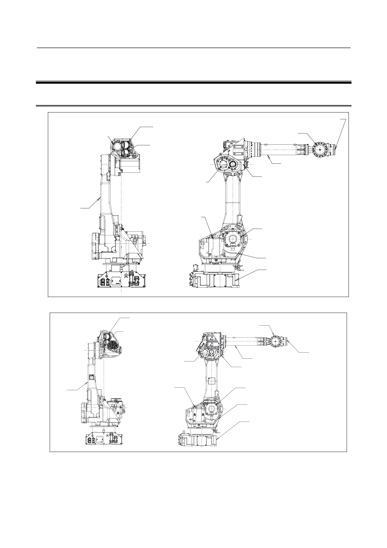
ROBOT CONFIGURATION
End effector
AC servo motor (M4)
mounting face
for J4-axis
Wrist unit
AC servo motor (M6)
for J6-axis
AC servo motor (M5)
for J5-axis
J3 arm
J3 casing
AC servo motor (M3)
for J3-axis
J2 arm
AC servo motor (M1)
for J1-axis
AC servo motor (M2)
for J2-axis
J2 unit
J1 unit
Fig. 3.1 (a) Mechanical unit configuration (M-710iC/50, M-710iC/70)
AC servo motor (M4)
for J4-axis
Wrist unit
AC servo motor (M5)
for J5-axis
End effector
J3 arm
mounting face
AC servo motor (M3)
for J3-axis
J3 casing
AC servo motor (M1)
AC servo motor (M2)
J2 arm
for J1-axis
for J2-axis
J2 unit
J1 unit
Fig. 3.1 (b) Mechanical unit configuration (M-710iC/50H)
- 11 -
3.BASIC SPECIFICATIONS
B-82274EN/09
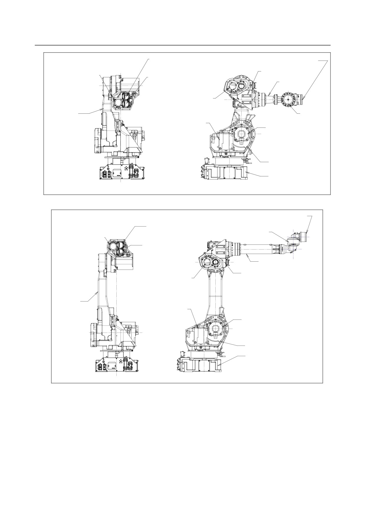
AC servo motor (M5)
End effector
for J5-axis
mounting face
J3 casing
AC servo motor (M6)
AC servo motor (M4)
for J6-axis
J3 arm
for J4-axis
AC servo motor (M3)
for J3-axis
J2 arm
Wrist unit
AC servo motor (M1)
for J1-axis
AC servo motor (M2)
for J2-axis
J2 unit
J1 unit
Fig. 3.1 (c) Mechanical unit configuration (M-710iC/50S)
End effector
mounting face
AC servo motor (M4)
for J4-axis
Wrist unit
AC servo motor (M6)
for J6-axis
AC servo motor (M5)
for J5-axis
J3 arm
J3 casing
AC servo motor (M3)
for J3-axis
J2 arm
AC servo motor (M1)
for J1-axis
AC servo motor (M2)
for J2-axis
J2 unit
J1 unit
Fig. 3.1 (d) Mechanical unit configuration (M-710iC/50E)
- 12 -
B-82274EN/09
3.BASIC SPECIFICATIONS
-
+
J6
J3
+
J4
(except 50H)
+
-
-
-
J5
+
(In case of 50H,
J2
it is J4)
-
J5
-
-
+
J6
+
J1
-
+
+
(M-710iC/50E)
(*) All axes are 0°at this posture.
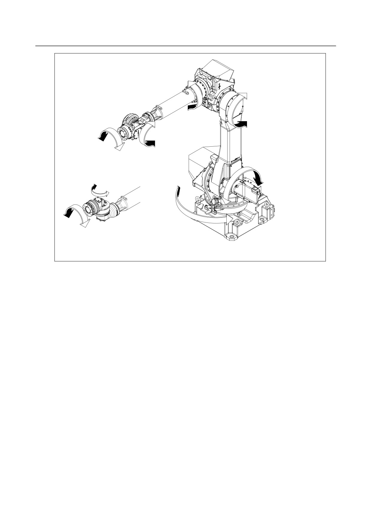
Fig. 3.1 (e) Each axis coordinates
- 13 -
3.BASIC SPECIFICATIONS
B-82274EN/09
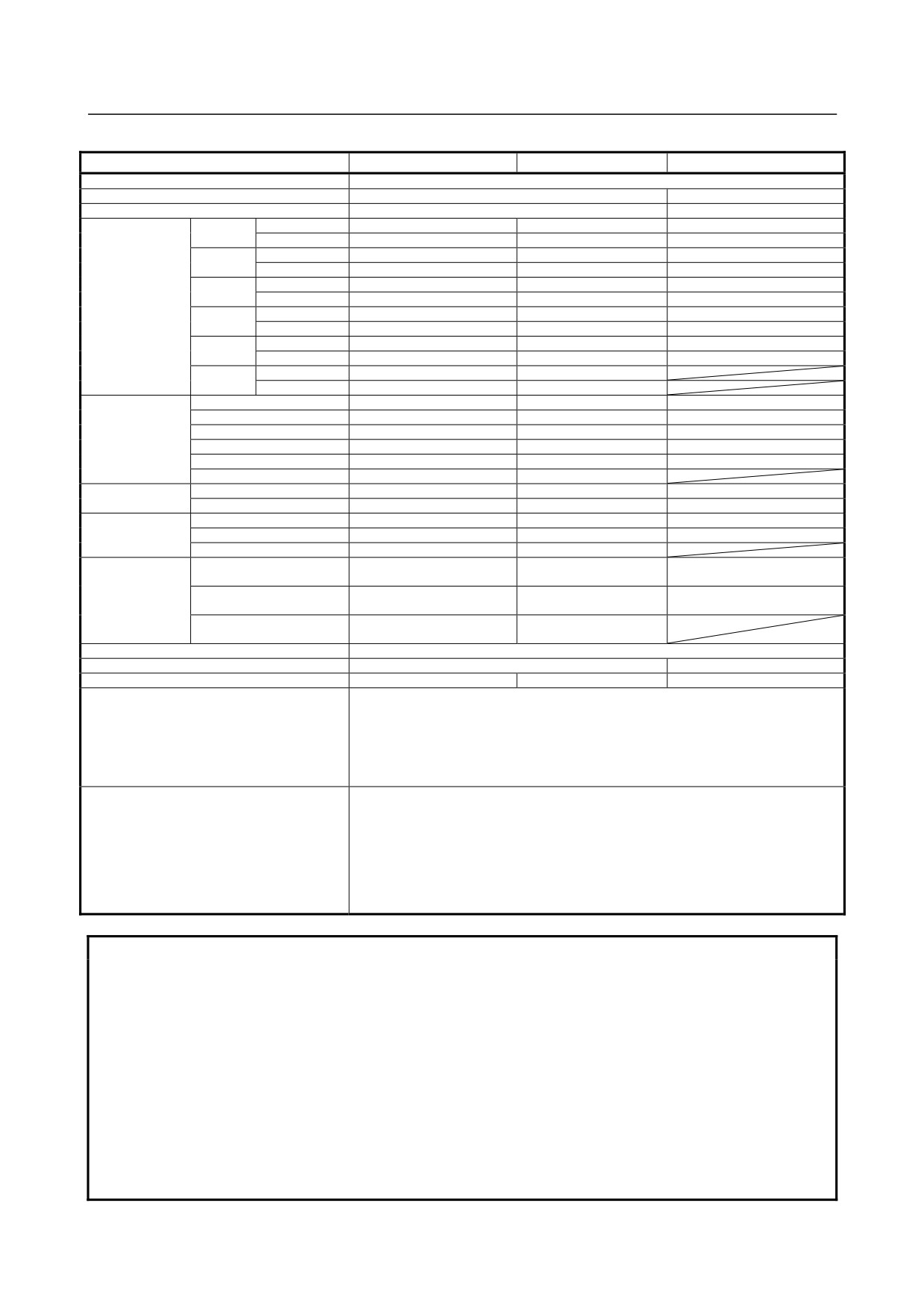
Specifications (1/2)
M-710iC/50
M-710iC/70
M-710iC/50H
Type
Articulated Type
Controlled axes
6 axes (J1, J2, J3, J4, J5, J6)
5 axes (J1, J2, J3, J4, J5)
Installation
Floor, upside-down, wall & angle mount
Floor, upside-down
Upper limit
180° (3.14rad)
180° (3.14rad)
180°(3.14rad)
J1-axis
Lower limit
-180° (-3.14rad)
-180° (-3.14rad)
-180° (-3.14rad)
Upper limit
135° (2.35rad)
135° (2.35rad)
135° (2.35rad)
J2-axis
Lower limit
-90° (-1.57rad)
-90° (-1.57rad)
-90º (-1.57rad)
Upper limit
280° (4.88rad)
280° (4.88rad)
280º ( 4.88rad)
J3-axis
Lower limit
-160° (-2.79rad)
-160° (-2.79rad)
-160º (-2.79rad)
Motion range
Upper limit
360° (6.28rad)
360° (6.28rad)
117º( 2.04rad)
J4-axis
Lower limit
-360° (-6.28rad)
-360° (-6.28rad)
-117º( -2.04rad)
Upper limit
125° (2.18rad)
125° (2.18rad)
360º ( 6.28rad)
J5-axis
Lower limit
-125° (-2.18rad)
-125° (-2.18rad)
-360º (-6.28rad)
Upper limit
360° (6.28rad)
360° (6.28rad)
J6-axis
Lower limit
-360° (-6.28rad)
-360° (-6.28rad)
J1-axis
175° /s (3.05rad/s)
160° /s (2.79rad/s)
175º/s (3.05rad/s)
J2-axis
175° /s (3.05rad/s)
120° /s (2.09rad/s)
175º/s (3.05rad/s)
Max motion
J3-axis
175° /s (3.05rad/s)
120° /s (2.09rad/s)
175º/s (3.05rad/s)
speed
J4-axis
250° /s (4.36rad/s)
225° /s (3.93rad/s)
175º/s (3.05rad/s)
(Note 1)
J5-axis
250° /s (4.36rad/s)
225° /s (3.93rad/s)
720º/s (12.57rad/s)
J6-axis
355° /s (6.20rad/s)
225° /s (3.93rad/s)
Max. load
At wrist
50kg
70kg
50kg
capacity
On J3 casing (Note 2)
15kg
15kg
15kg
J4
206N・m (21kgf・m)
294N・m (30kgf・m)
150N・m (15.3kgf・m)
Allowable load
J5
206N・m (21kgf・m)
294N・m (30kgf・m)
68N・m (6.9kgf・m)
moment at wrist
J6
127N・m (13kgf・m)
147N・m (15kgf・m)
2
28kg・m
28kg・m2
6.3kg・m2
J4
(286kgf・cm・s2)
(286kgf・cm・s2)
(64.3kgf・cm・s2)
2
Allowable load
28kg・m
28kg・m2
2.5kg・m2
J5
inertia at wrist
(286kgf・cm・s2)
(286kgf・cm・s2)
(25.5kgf・cm・s2)
2
11kg・m
11kg・m2
J6
(112kgf・cm・s2)
(112kgf・cm・s2)
Drive method
Electric servo drive by AC servo motor
Repeatability
±0.07mm
±0.15mm
Mass
560kg
560kg
540kg
71.3dB
NOTE
This value is equivalent continuous A-weighted sound pressure level that
Acoustic noise level (Note 2)
applied with ISO11201 (EN31201). This value is measured with the following
conditions.
Maximum load and speed
-
Operating mode is AUTO
Ambient temperature: 0 - 45°C (Note 3)
Ambient humidity: Normally 75%RH or less
No dew, nor frost allowed.
Short time (within one month)
Installation environment
Max 95%RH
Height: Up to 1,000 meters above the sea level required, no particular
provision for attitude.
Vibration: 0.5G or less
Free of corrosive gases (Note 4)
NOTE
1 In case of short distance motion, the axis speed doesn't reach maximum one.
2 The Max. load capacity at J3 casing is restricted by the load weight at wrist. For
details, see Section 3.5.
3 When robot is used in low temperature environment that is near to 0ºC,or robot is
not operated for a long time in the environment that is less than 0ºC in a holiday or
the night, because viscous resistance of the drive train is so big that may cause
occurrence of collision detect alarm (SRVO -050) etc. In this case, we recommend
performing the warm up operation for several minutes.
4 Contact the service representative, if the robot is to be used in an environment or a
place subjected to severe vibrations, heavy dust, cutting oil splash and or other
foreign substances.
- 14 -
B-82274EN/09
3.BASIC SPECIFICATIONS
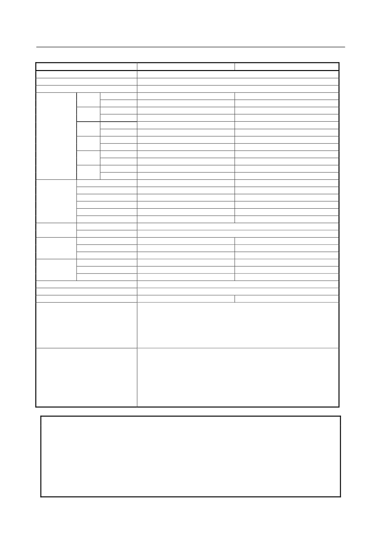
Specifications (2/2)
M-710iC/50S
M-710iC/50E
Type
Articulated Type
Controlled axes
6 axes (J1, J2, J3, J4, J5, J6)
Installation
Floor, upside-down, wall & angle mount
Upper limit
180º ( 3.14rad)
180º ( 3.14rad)
J1-axis
Lower limit
-180º (-3.14rad)
-180º (-3.14rad)
Upper limit
112º ( 1.95rad)
135º ( 2.35rad)
J2-axis
Lower limit
-57º (-0.99rad)
-90º (-1.57rad)
Upper limit
279º ( 4.87rad)
280º ( 4.88rad)
J3-axis
Motion range
Lower limit
-97º (-1.69rad)
-160º (-2.79rad)
Upper limit
360º ( 6.28rad)
360º ( 6.28rad)
J4-axis
Lower limit
-360º (-6.28rad)
-360º (-6.28rad)
Upper limit
125º ( 2.18rad)
190º ( 3.31rad)
J5-axis
Lower limit
-125º (-2.18rad)
-190º (-3.31rad)
Upper limit
360º ( 6.28rad)
360º ( 6.28rad)
J6-axis
Lower limit
-360º (-6.28rad)
-360º (-6.28rad)
J1-axis
175º/s (3.05rad/s)
175º/s (3.05rad/s)
J2-axis
175º/s (3.05rad/s)
175º/s (3.05rad/s)
Max motion
J3-axis
175º/s (3.05rad/s)
175º/s (3.05rad/s)
speed
J4-axis
250º/s (4.36rad/s)
250º/s (4.36rad/s)
(Note 1)
J5-axis
250º/s (4.36rad/s)
240º/s (4.19rad/s)
J6-axis
355º/s (6.20rad/s)
340º/s (5.93rad/s)
Max. load
At wrist
50kg
capacity
On J3 casing (Note 2)
15kg
Allowable load
J4-axis
206N・m (21kgf・m)
206N・m (21kgf・m)
moment at
J5-axis
206N・m (21kgf・m)
176N・m (18kgf・m)
wrist
J6-axis
127N・m (13kgf・m)
98N・m (10kgf・m)
J4-axis
28kg・m2 (286kgf・cm・s2)
28kg・m2 (286kgf・cm・s2)
Allowable load
J5-axis
28kg・m2 (286kgf・cm・s2)
10.8kg・m2 (110kgf・cm・s2)
inertia at wrist
J6-axis
11kg・m2 (112kgf・cm・s2)
3.3kg・m2 (34kgf・cm・s2)
Drive method
Electric servo drive by AC servo motor
Repeatability
±0.07mm
Mass
545kg
560kg
71.3dB
NOTE
This value is equivalent continuous A-weighted sound pressure level that
Acoustic noise level
applied with ISO11201 (EN31201). This value is measured with the following
conditions.
-
Maximum load and speed
-
Operating mode is AUTO
Ambient temperature: 0 - 45°C
(Note 3)
Ambient humidity: Normally 75%RH or less
No dew, nor frost allowed.
Short time (within one month)
Installation environment
Max 95%RH
Height:
Up to 1,000 meters above the sea level required, no
particular provision for attitude.
Vibration: 0.5G or less
Free of corrosive gases (Note 4)
NOTE
1 In case of short distance motion, the axis speed doesn't reach maximum one.
2 The Max. load capacity at J3 casing is restricted by the load weight at wrist.
For details, see Section 3.5.
3 When robot is used in low temperature environment that is near to 0ºC,or robot
is not operated for a long time in the environment that is less than 0ºC in a
holiday or the night, because viscous resistance of the drive train is so big that
may cause occurrence of collision detect alarm (SRVO -050) etc. In this case,
we recommend performing the warm up operation for several minutes.
- 15 -
3.BASIC SPECIFICATIONS
B-82274EN/09
NOTE
4 Contact the service representative, if the robot is to be used in an environment
or a place subjected to severe vibrations, heavy dust, cutting oil splash and or
other foreign substances.
3.2
MECHANICAL UNIT OPERATION AREA AND
INTERFERENCE AREA
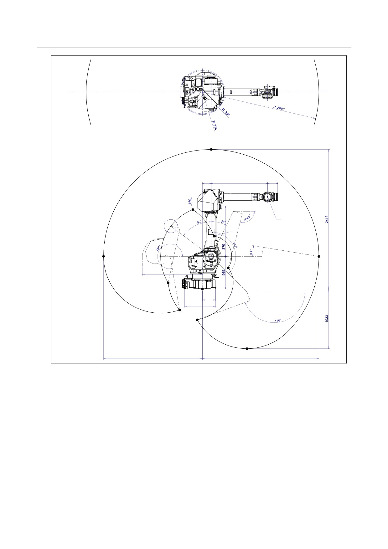
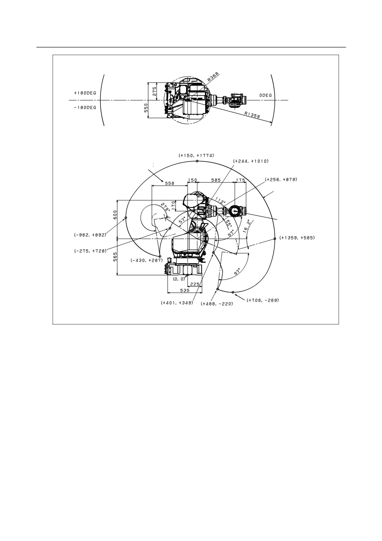
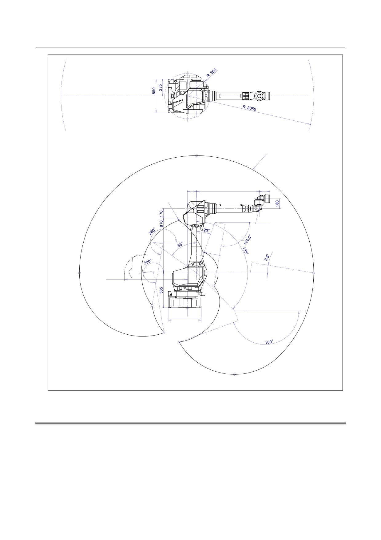
Fig. 3.2 (a), (b) and (c) show the robot interference area. When installing peripheral devices, be careful
to clear away any objects that are the robot and the robot’s motion path in normal operation.
Motion range of
J5-axis rotation center
J5-axis rotation
center
J3-axis
rear side
interference
area
Fig. 3.2 (a) Interference area (M-710iC/50, /70)
- 16 -
B-82274EN/09
3.BASIC SPECIFICATIONS
+180DEG
0DEG
-180DEG
With J2 cover
Without J2 cover
(+150,+2418)
150
970
175
(-165,+1377)
258°
J4-axis rotation
center
(+199,+915)
(-1703,+565)
(+2003,+565)
(+443,+368)
1034
(-590,+107)
(0,0)
225
535
(-394,-362)
(-92,-532)
Motion range of
J4-axis rotation center
(+765,-1033)
1703
2003
Fig. 3.2 (b) Interference area (M-710iC/50H)
- 17 -
3.BASIC SPECIFICATIONS
B-82274EN/09
J3-axisrear side
interference area
Motion range of
J5-axis rotation center
J5-axis rotation
center
Fig. 3.2 (c) Interference area (M-710iC/50S)
- 18 -
B-82274EN/09
3.BASIC SPECIFICATIONS
+180deg
0deg
-180deg
(+150,+2465)
Motion range of
J5-axis rotation center
150
1016
170
J5-axis rotation
center
(+254,+900)
J3-axis rearside
(-1750,+585)
interference area
(+2050,+565)
1018
(+430,+353)
(-572,+34)
(0,0)
225
535
(-376,-406)
(-131,-557)
(+765,-1080)
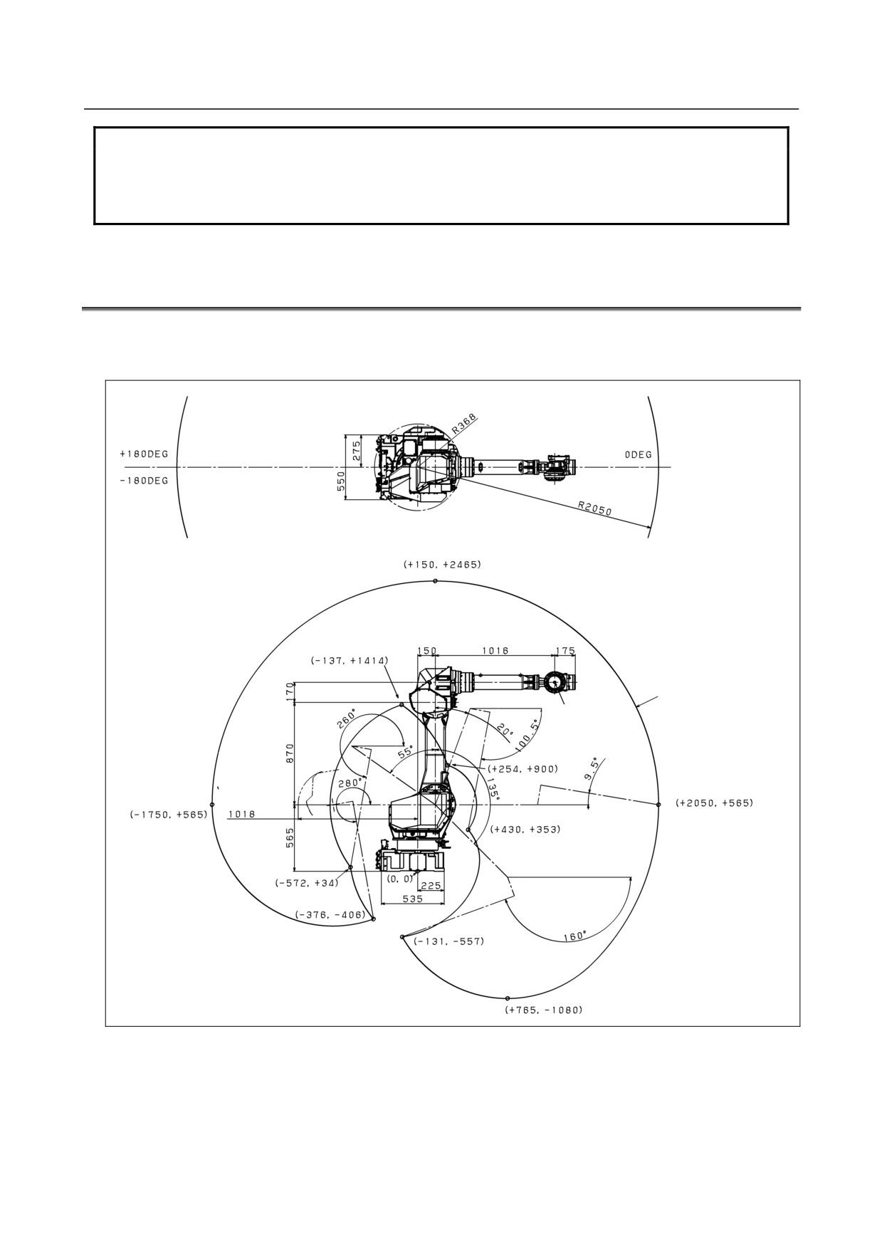
Fig. 3.2 (d) Interference area (M-710iC/50E)
3.3
ZERO POINT POSITION AND MOTION LIMIT
Zero point and software motion limit are provided for each controlled axis. The robot cannot exceed the
software motion limit unless there is a failure of the system causing loss of zero point position or there is
a system error.
Exceeding the software motion limit of a controlled axis is called overtravel (OT). Overtravel is
detected at both ends of the motion limit for each axis.
In addition, the motion range limit by a mechanical stopper or limit switch is also prepared to
improve safety.
- 19 -
3.BASIC SPECIFICATIONS
B-82274EN/09
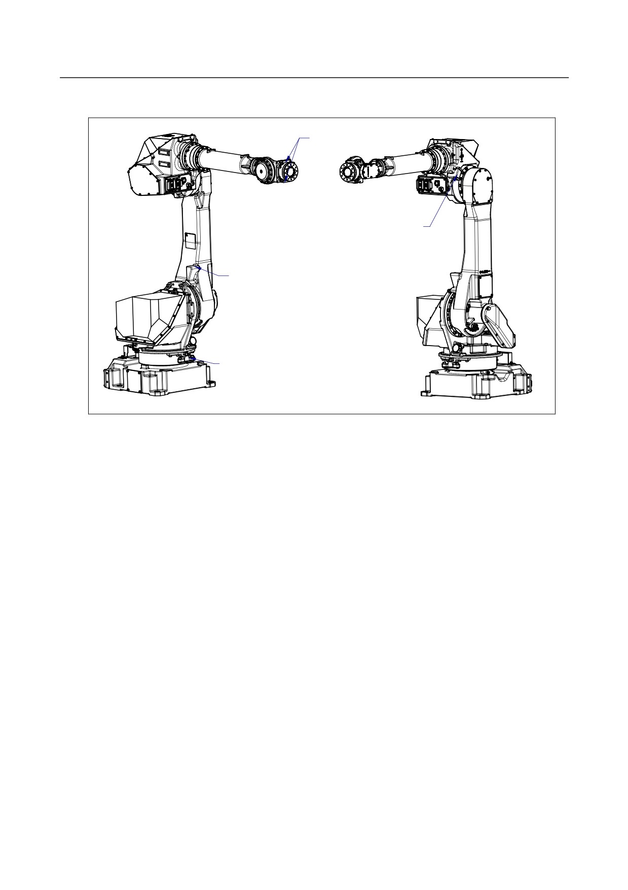
Fig 3.3 (a) shows the position of mechanical stopper. See Section 6.2 about movable mechanical stopper.
There is no mechanical stopper for J5-axis of M-710iC/50E.
J5-axis mechanical stopper
J3-axis mechanical stopper
J2-axis mechanical stopper
J1-axis mechanical stopper
Fig. 3.3 (a) Position of mechanical stopper
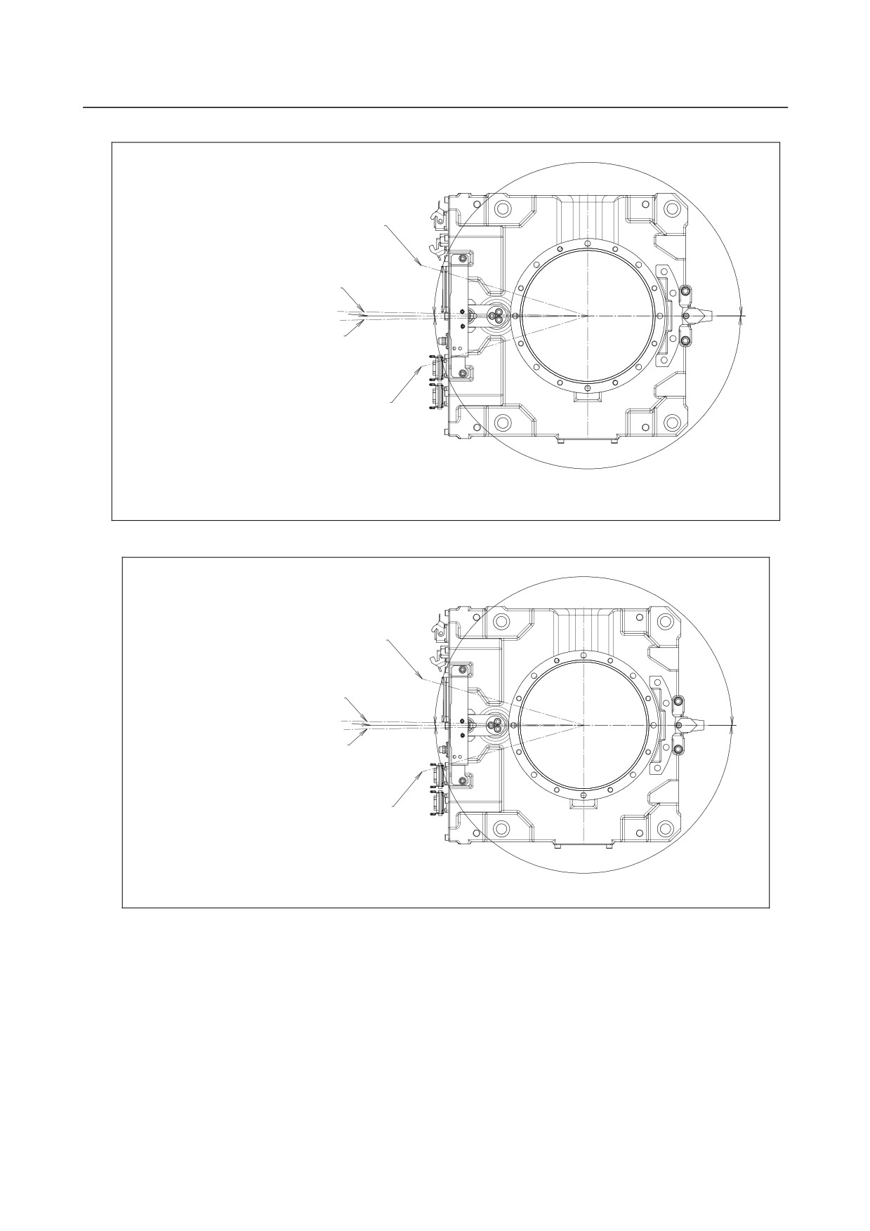
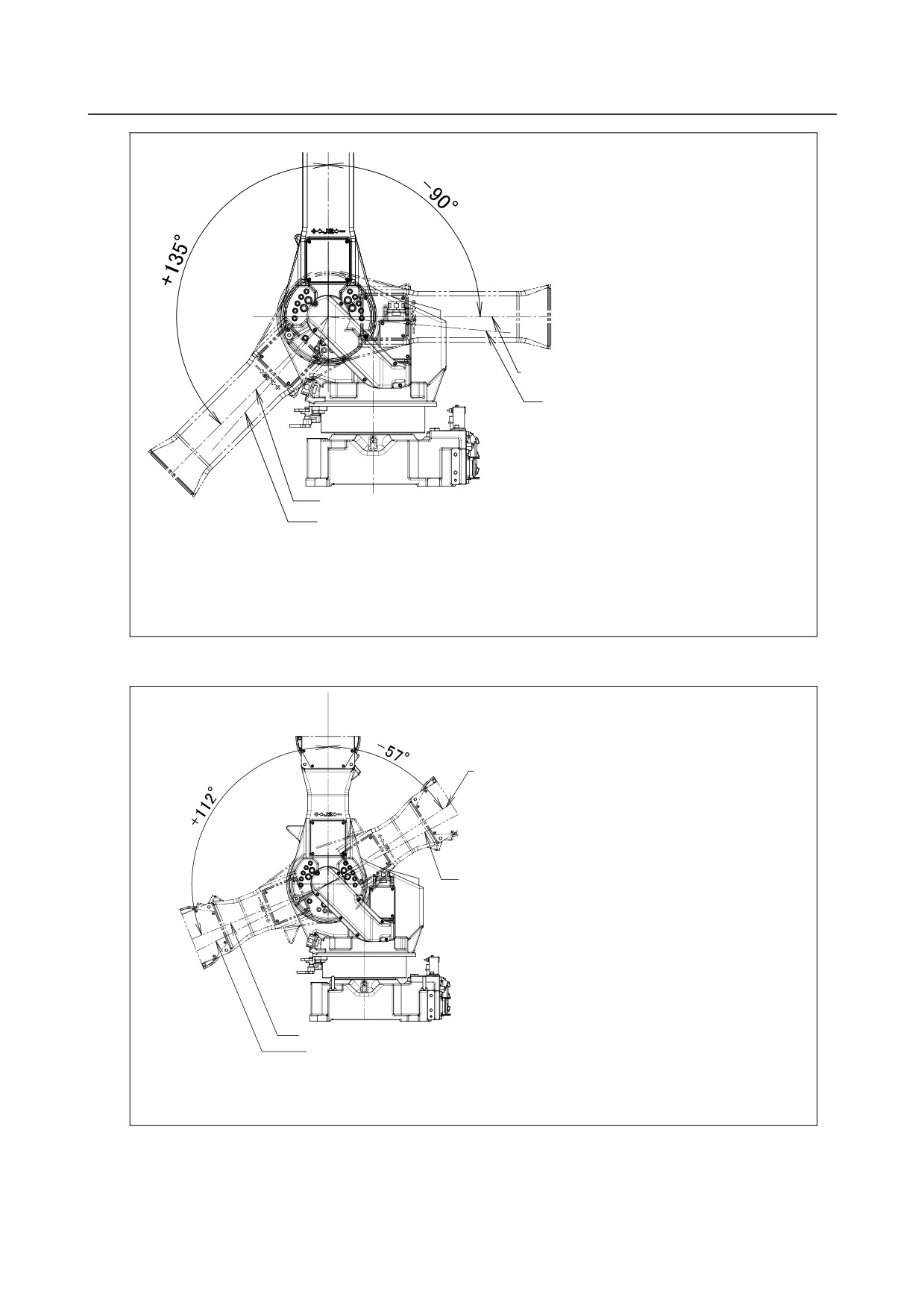
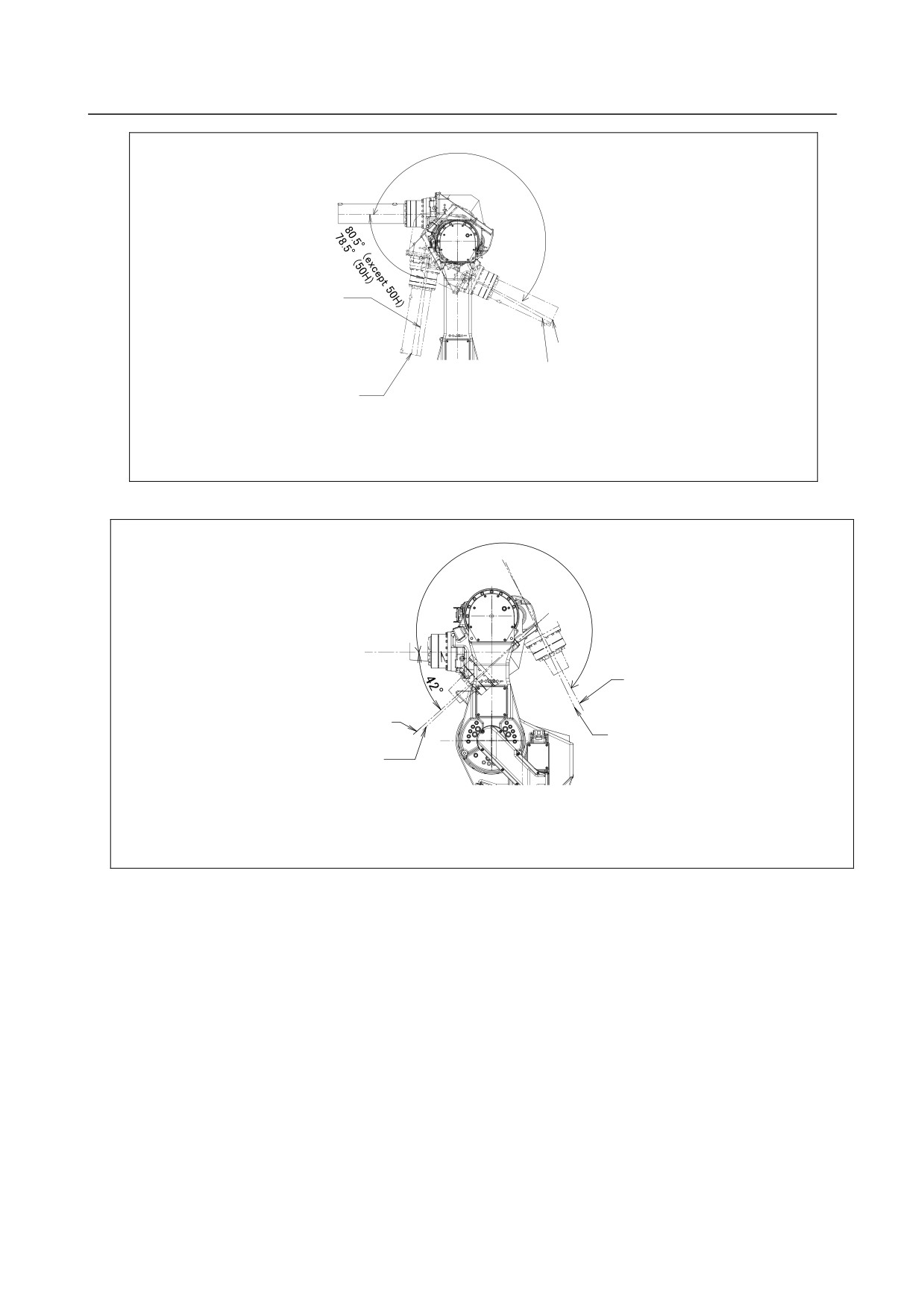
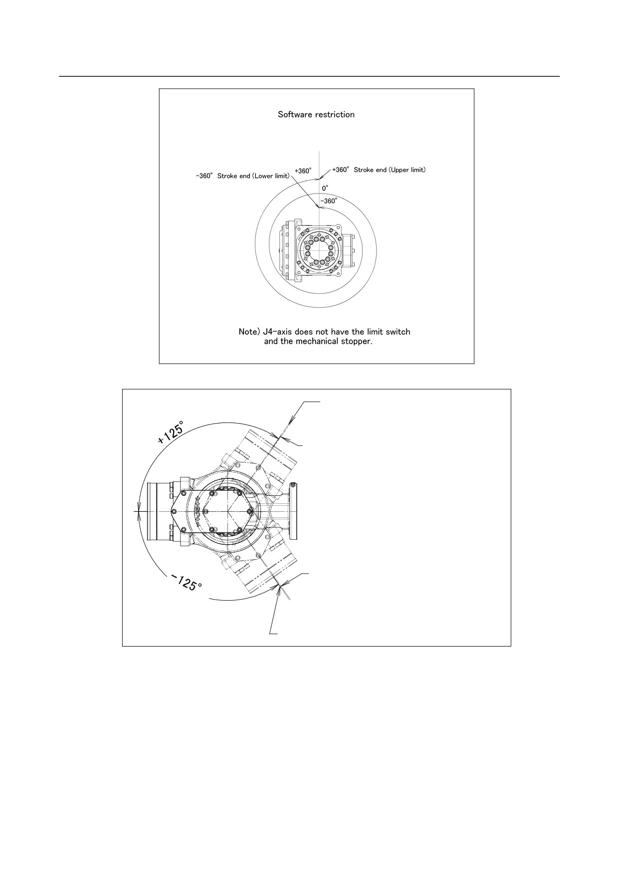
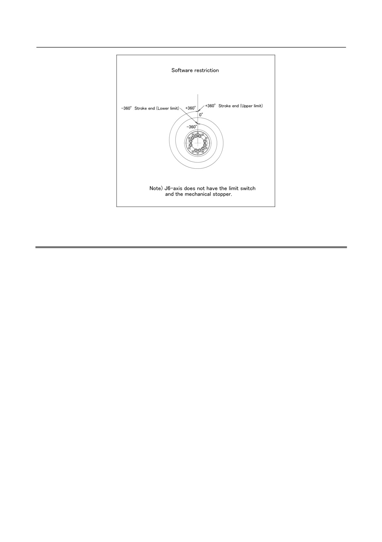
Fig.3.3 (b) - (l) show the zero point and motion limit, LS detection position, and maximum stopping
distance (stopping distance in condition of max.speed and max.load) of each axis.
Only in case of J1 to J3 axis, robot stops by transforming mechanical stopper. Be sure to exchange
transformed stopper to new one. Don’t reconstruct the mechanical stopper. There is a possibility that the
robot doesn't stop normally.
* The motion range can be changed. For information on how to change the motion range, see Chapter
6, “AXIS LIMIT SETUP”.
- 20 -
B-82274EN/09
3.BASIC SPECIFICATIONS
+180°
-197°The maximum stopping distance(position)
-181°Limit switch detection position
±180°Stroke end
0°
+181°Limit switch detection position
+197°The maximum stopping distance(position)
-180°
(Note) The limit switch of J1-axis is option.
Fig. 3.3 (b) J1-axis motion limit (M-710iC/50, 70, 50H,50S, 50E)
+180°
-196°The maximum stopping distance(position)
-181°Limit switch detection position
±180°Stroke end
0°
+181°Limit switch detection position
+196°The maximum stopping distance(position)
-180°
(Note) The limit switch of J1-axis is option
Fig. 3.3 (c) J1-axis motion limit (M-710iC/70)
- 21 -
3.BASIC SPECIFICATIONS
B-82274EN/09
0°
-90°Stroke end(Lower limit)
-95°The maximum stopping
distance(position)
+135°Stroke end(Upper limit)
+140°The maximum stopping distance(position)
Note) The J2-axis does't have limit switch.
Motion limit is restricted by the position of the J3-axis
Fig. 3.3 (d) J2-axis motion limit (M-710iC/50, 70, 50H, 50E)
0°
-57v Stroke end(Lower limit)
-62°The maximum stopping distance(position)
+112°Stroke end(Upper limit)
+117°The maximum stopping distance(position)
Note) The J2-axis does't have limit switch.
Motion limit is restricted by the position of the J3-axis
Fig. 3.3 (e) J2-axis motion limit (M-710iC/50S)
- 22 -
B-82274EN/09
3.BASIC SPECIFICATIONS
205°
0°
J2+J3=-84°
The maximum stopping distance (position)
(except 50H)
J2+J3=205v Stroke end (Upper limit)
J2+J3=-82°
The maximum stopping distance (position)
J2+J3=208.5°The maximum stopping
(50H)
distance (position)
J2+J3=-80.5v Stroke end (Lower limit)
(except 50H)
J2+J3=-78.5v Stroke end (Lower limit)
Note) The J3-axis does't have limit switch.
(50H)
Motion limit is restricted by the positon of the J2-axis.
Fig. 3.3 (f) J3-axis motion limit (M-710iC/50, 70, 50H, 50E)
242°
0°
J2+J3=242v
Stroke end (Upper limit)
J2+J3=-42°Stroke end (Lower limit)
J2+J3=+245.5°
The maximum stopping distance (position)
J2+J3=-45°
The maximum stopping distance (position)
Note) The J3-axis does't have limit switch.
Motion limit is restricted by the positon of the J2-axis.
Fig. 3.3 (g) J3-axis motion limit (M-710iC/50S)
- 23 -
3.BASIC SPECIFICATIONS
B-82274EN/09
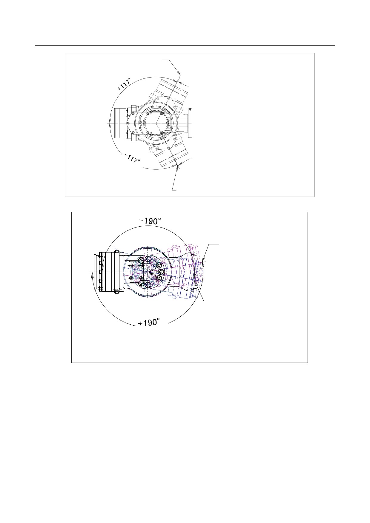
Fig. 3.3 (h) J4-axis motion limit (Except M-710iC/50H)
+125°Stroke end (Upper limit)
+125.5°The maximum stopping
disatance (position)
0°
-125.5°The maximum stopping
disatance (position)
-125°Stroke end (Lower limit)
Fig. 3.3 (i) J5-axis motion limit
(M-710iC/50, 70, 50S)
- 24 -
B-82274EN/09
3.BASIC SPECIFICATIONS
+117°Stroke end (Upper limit)
+117.6°The maximum stopping
distance (position)
0°
-117.6°The maximum stopping
distance (position)
-117°Stroke end (Lower limit)
Fig. 3.3 (j) J4-axis motion limit
(M-710iC/50H)
+190v Stroke end
(Upper limit)
0°
-190v Stroke end
(Lower limit)
Note) There is no mechanical stopper
for J5-axis.
Fig. 3.3 (k) J5-axis motion limit
(M-710iC/50E)
- 25 -
3.BASIC SPECIFICATIONS
B-82274EN/09
Fig. 3.3 (l) J6-axis motion limit (Except M-710iC/50H)
J5-axis motion limit (M-710iC/50H)
3.4
WRIST LOAD CONDITIONS
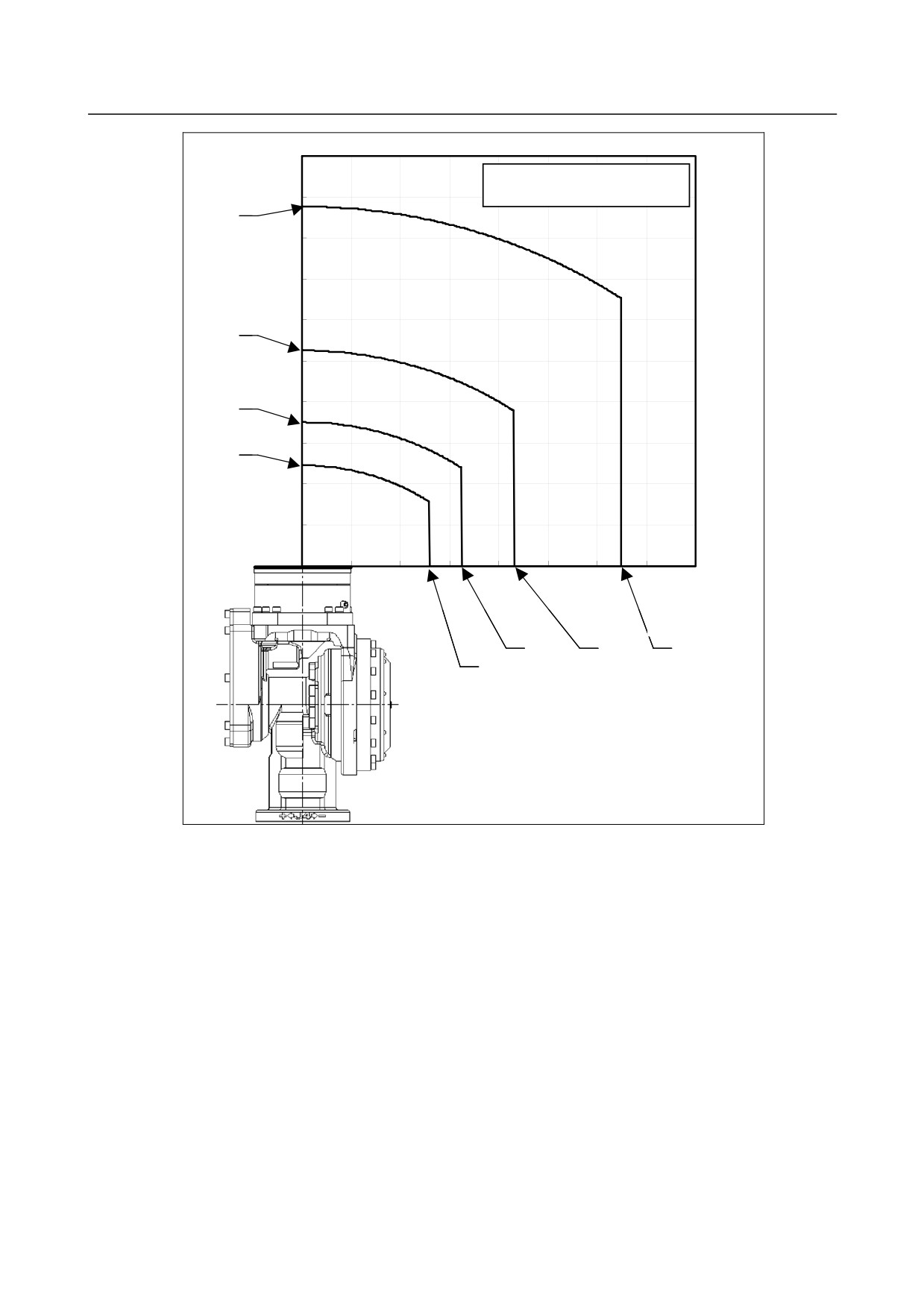
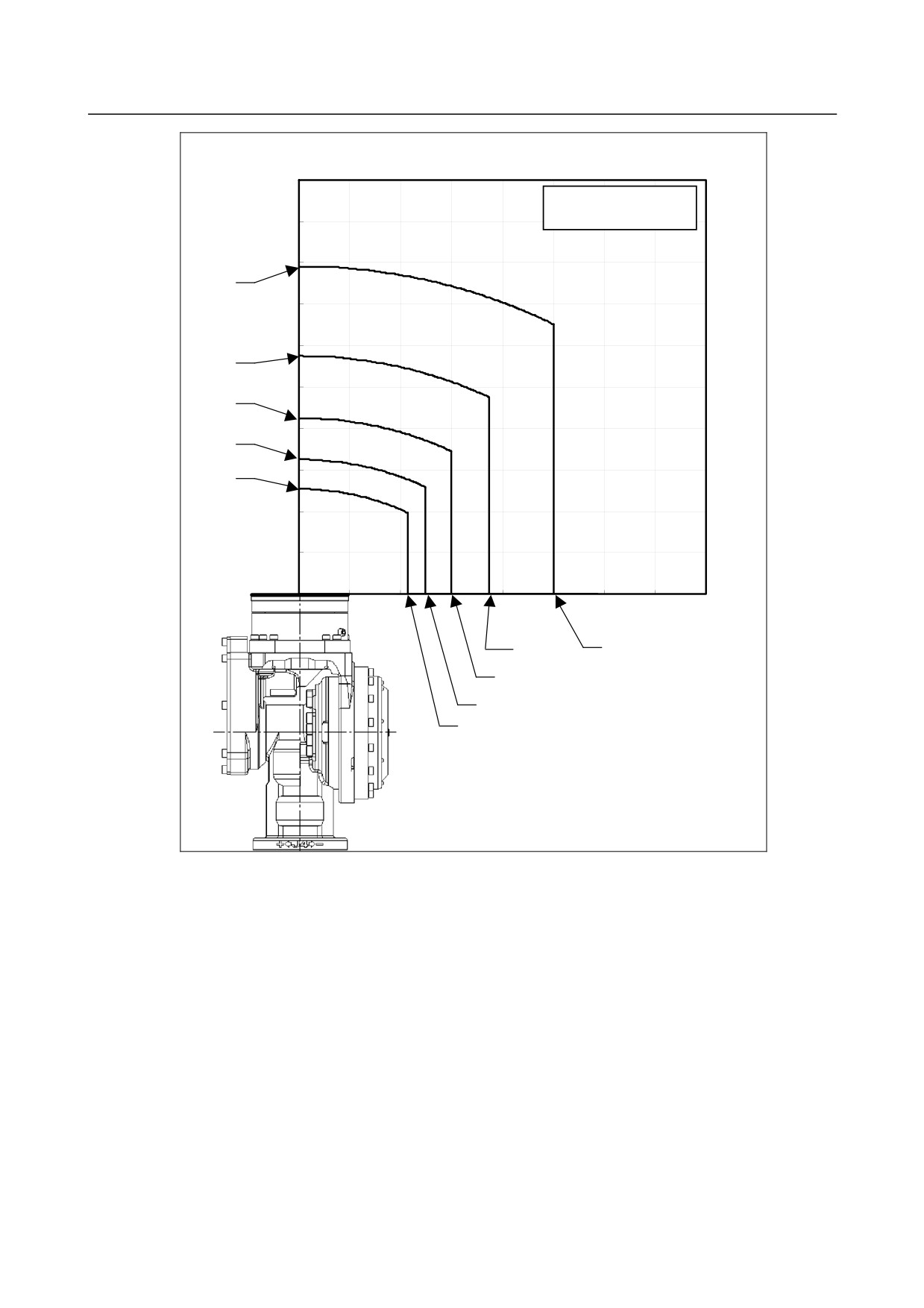
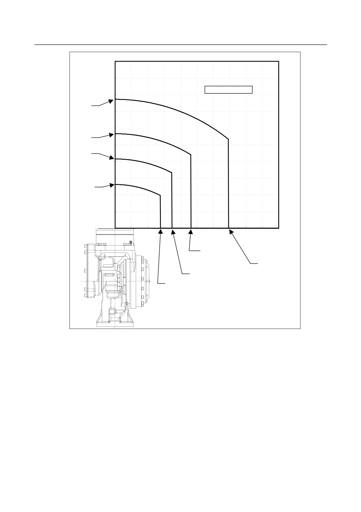
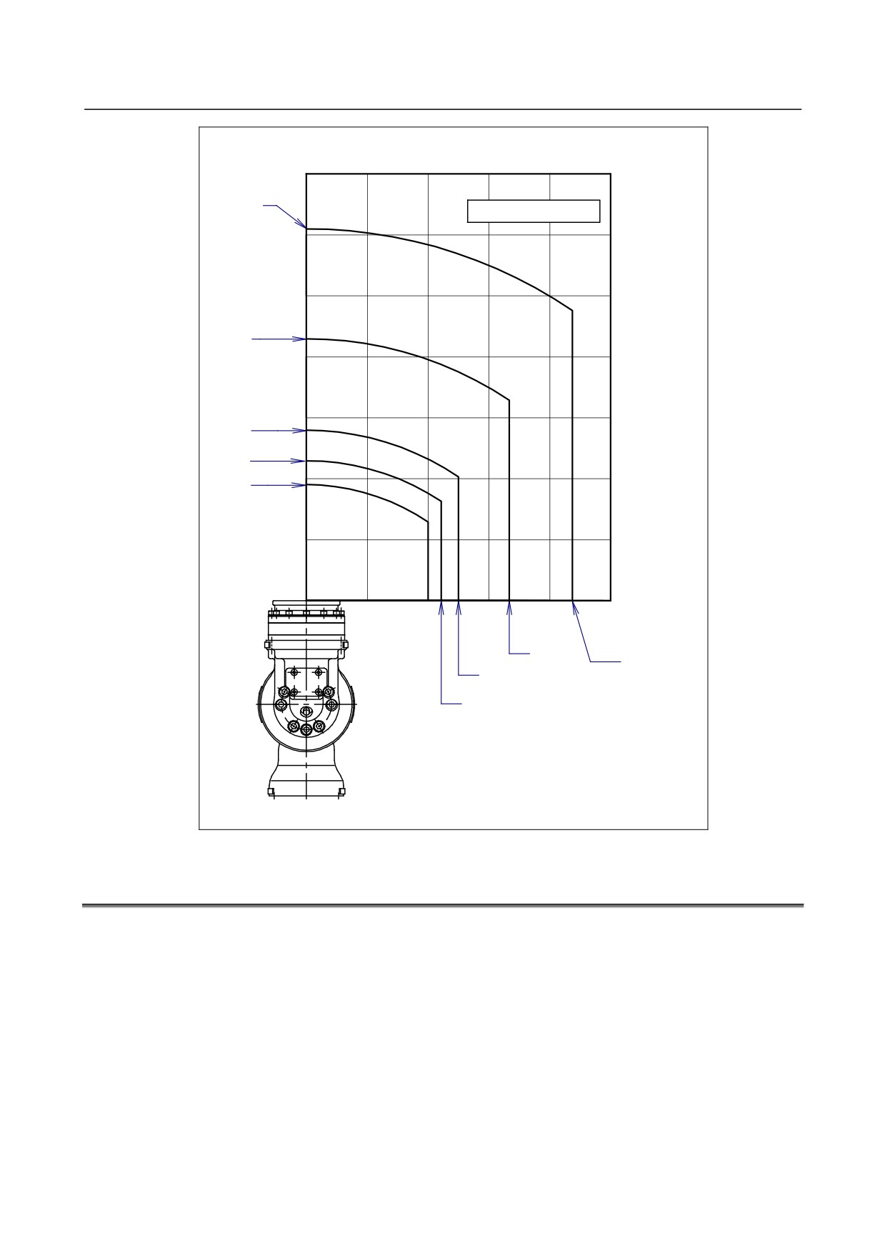
Fig. 3.4 (a) to (d) are diagrams to limit loads applied to the wrist. Apply a load within the region
indicated in the graph. Apply the conditions of the allowable load moment and the allowable load inertia.
See Section 3.1 about allowable load moment and the allowable load inertia.
- 26 -
B-82274EN/09
3.BASIC SPECIFICATIONS
100
Z(cm)
20kg
M-710iC/50, 50S
90
87.6
80
70
60
52.6
30kg
50
40
35.1
40kg
30
24.5
50kg
20
10
20
30
40
50
60
70
80
X,Y(cm)
32.4
43.2
64.8
26.0
Fig. 3.4 (a) Wrist load diagram (M-710iC/50, M-710iC/50S)
- 27 -
3.BASIC SPECIFICATIONS
B-82274EN/09
Z(cm)
100
M-710iC/70
90
80
79.1
30kg
70
60
57.5
40kg
50
42.5
50kg
40
32.5
60kg
30
25.4
70kg
20
10
20
30
40
50
60
70
80
37.5
50.0
X,Y(cm)
30.0
25.0
21.4
Fig. 3.4 (b) Wrist load diagram (M-710iC/70)
- 28 -
B-82274EN/09
3.BASIC SPECIFICATIONS
50
Z(cm)
45
M-710iC/50H
40
20kg
38.6
35
30
30kg
28.3
25
20.8
40kg
20
15
50kg
13.1
10
5
15
20
25
30
35
40
45
50
X,Y(cm)
23.1
34.7
17.3
13.9
Fig. 3.4 (c) Wrist load diagram (M-710iC/50H)
- 29 -
3.BASIC SPECIFICATIONS
B-82274EN/09
Z (cm)
70
61.0
20kg
M-710iC/50E
60
50
30kg
43.0
40
30
28.0
40kg
45kg
23.0
20
19.0
50kg
10
10
20
30
40
50
X,Y(cm)
33.3
43.8
25.0
22.2
Fig. 3.4 (d) Wrist load diagram (M-710iC/50E)
3.5
LOAD CONDITIONS ON J3 CASING
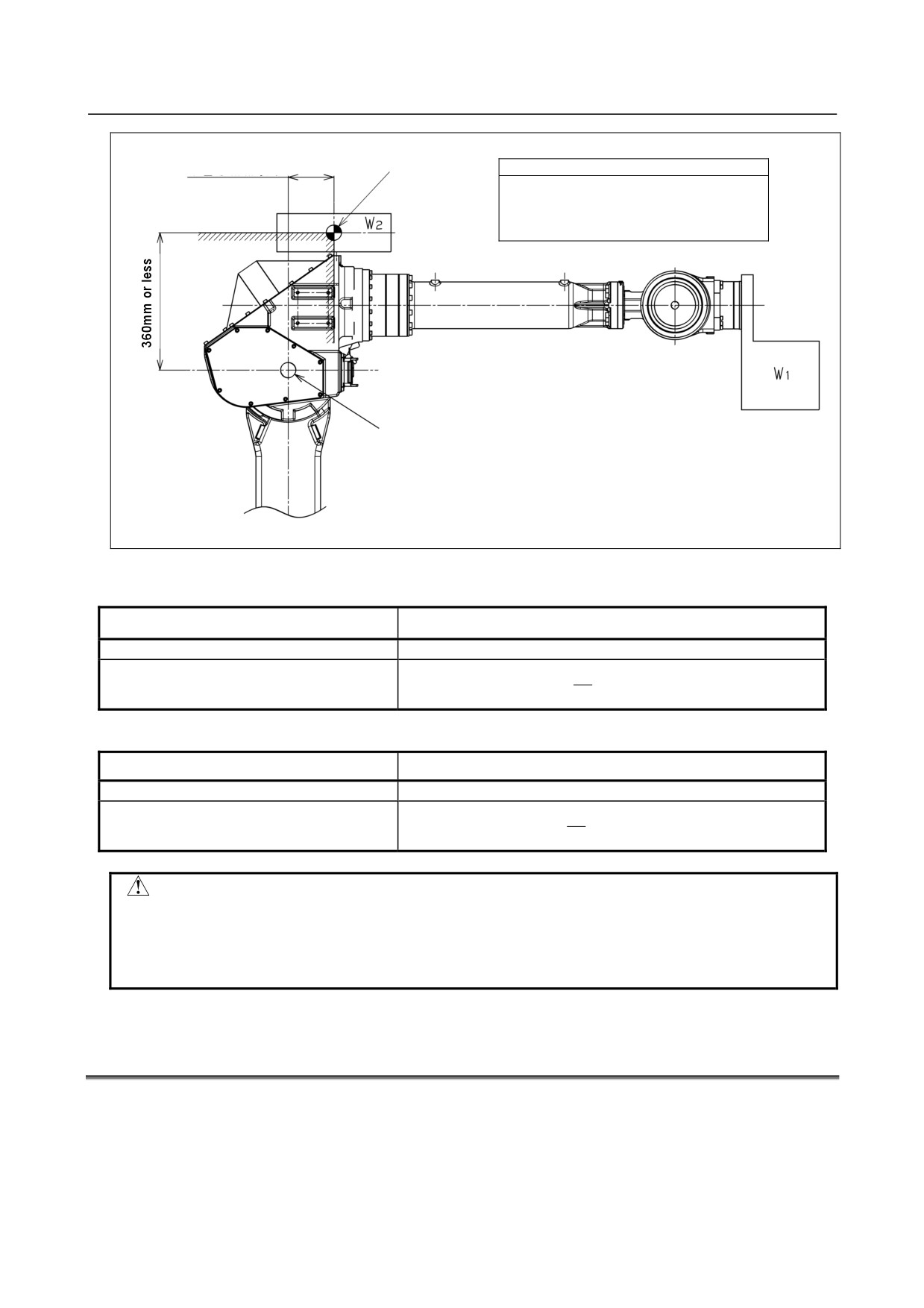
Table 3.5 (a),(b) and Fig. 3.5 show J3 casing load condition.
(The J3 casing load weight is limited according to the wrist load weight.)
- 30 -
B-82274EN/09
3.BASIC SPECIFICATIONS
J3 casing
120mm or less
Condition
load center
The load center must position 120 mm or
less forward of the J3-axis rotation
center in the wrist direction and 360 mm
or less above the rotation center.
J3-axis rotation center
Fig. 3.5 J3 casing load condition
Table 3.5 (a) J3 casing load condition (M-710iC/50, /50H, /50S, /50E)
W
W
Wrist load weight
1
J3 casing load weight
2
43 kg or less
15 kg or less
Equal to or more than 43 kg and equal to or
15
W
≤−
×(50−W
[
kg])
2
1
less than 50 kg
7
Table 3.5 (b) J3 casing load condition (M-710iC/70)
Wrist load weight
W
J3 casing load weight
W
1
2
63 kg or less
15 kg or less
Equal to or more than 63 kg and equal to or
15
W
≤
×(70−W
[
kg])
2
1
less than 70 kg
7
CAUTION
• Do not put load on J3 arm. (There is no problem for putting load on J3 casing.)
• If equipment is installed to J3 arm, it is dangerous because it rotate with J3 arm.
(except M-710iC/50H)
• If you put load on J3 arm, unavoidably, treat it as wrist load.
3.6
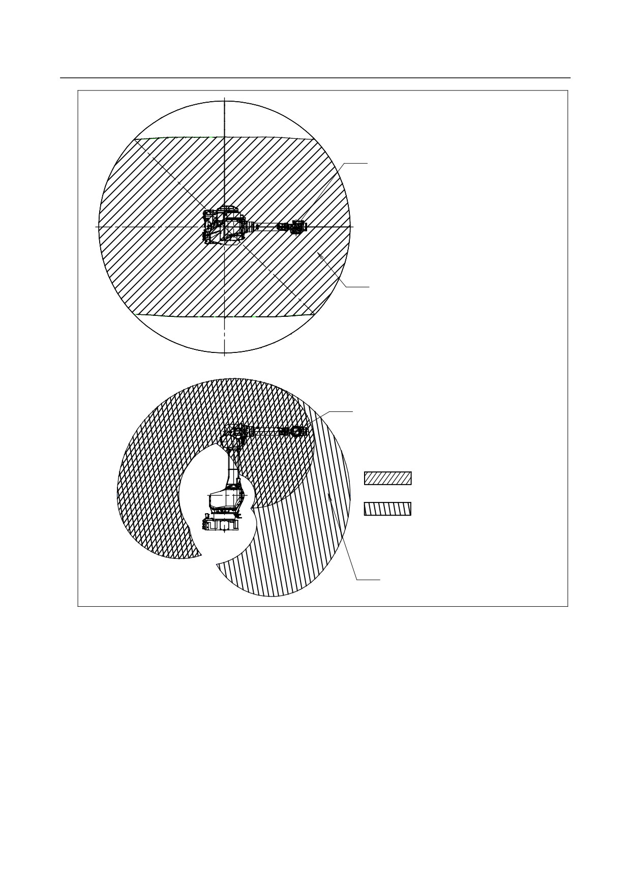
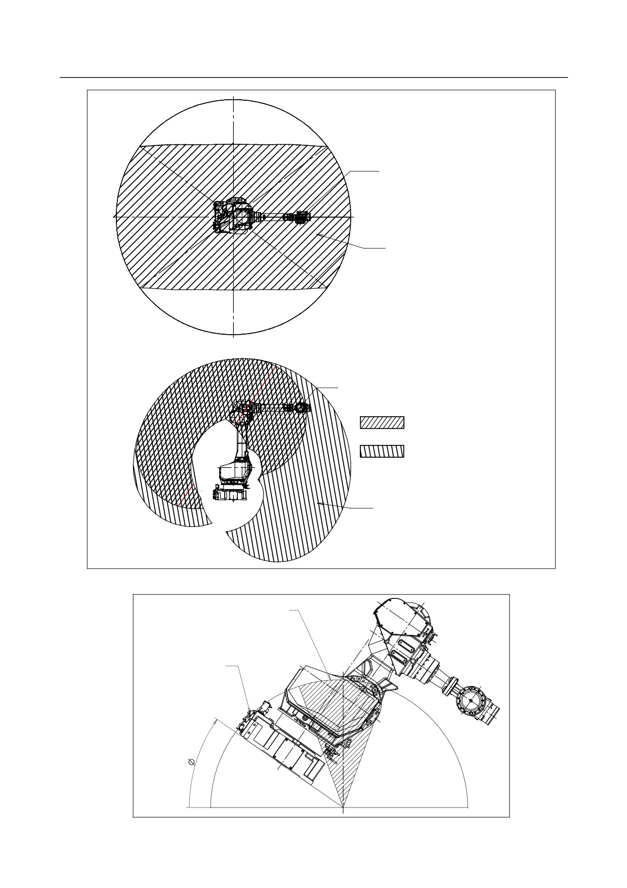
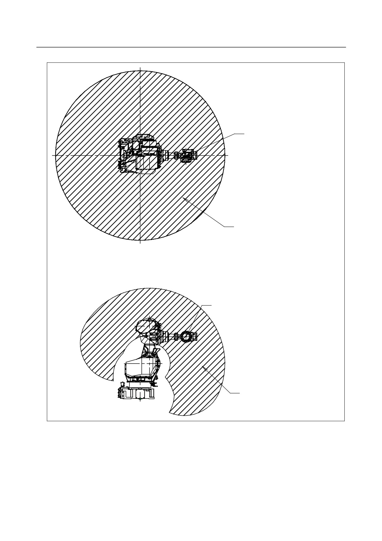
MOTION RANGE FOR WALL/INCLINED SURFACE
MOUNTED ROBOTS
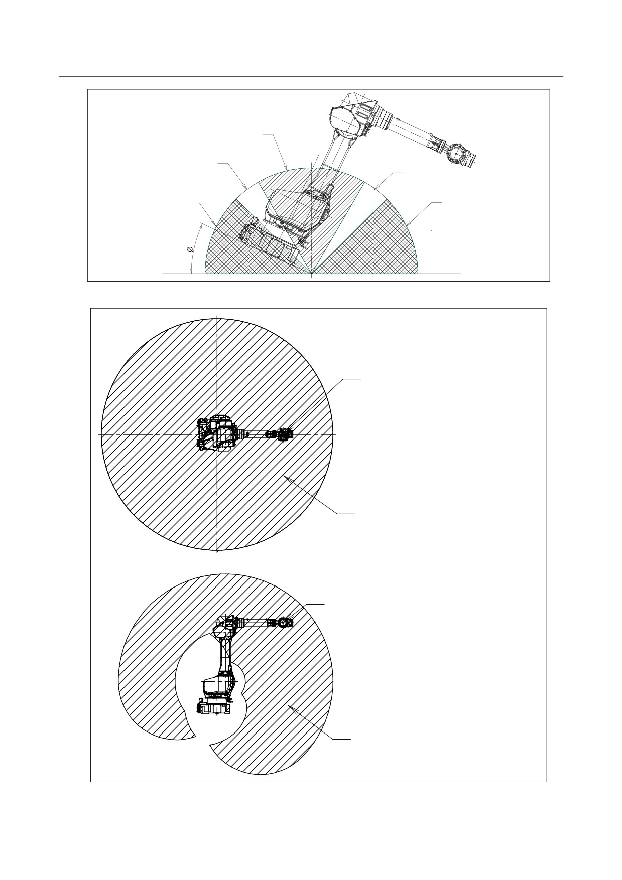
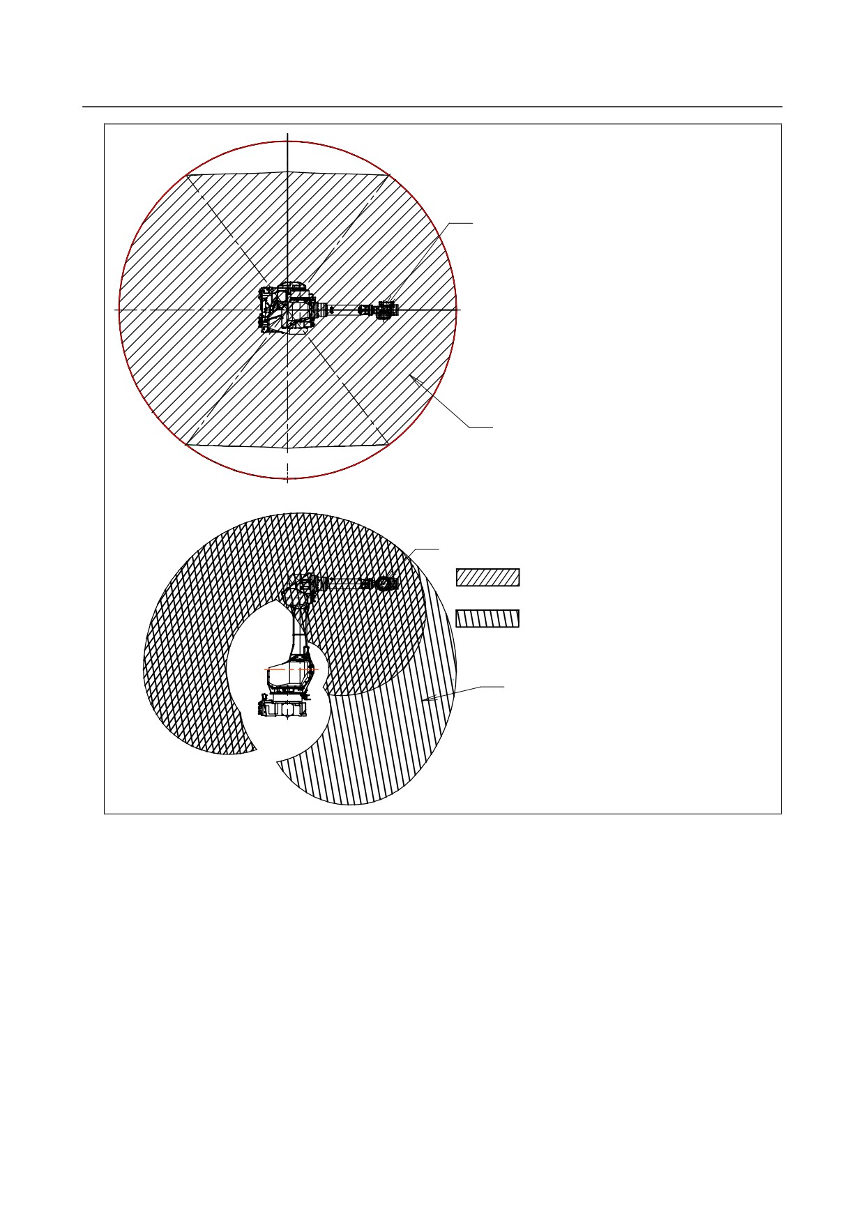
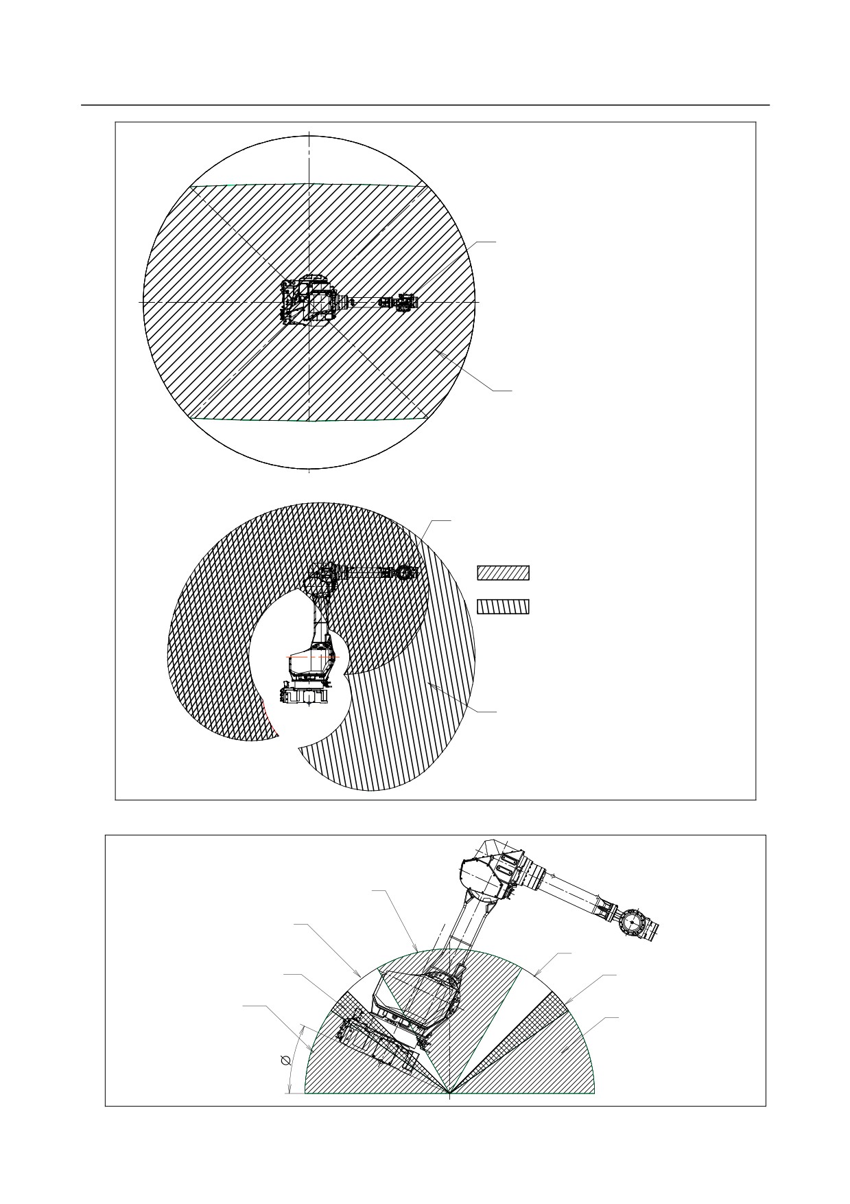
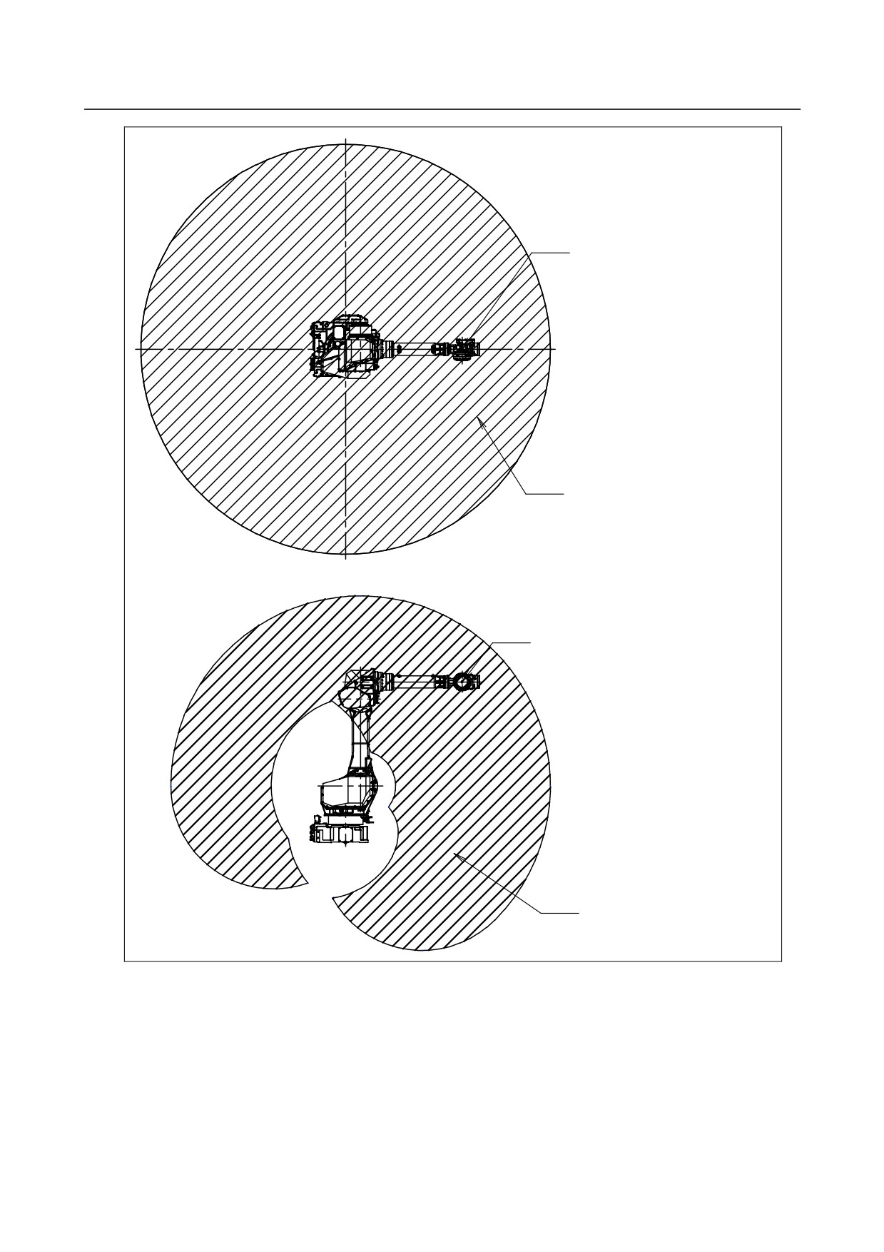
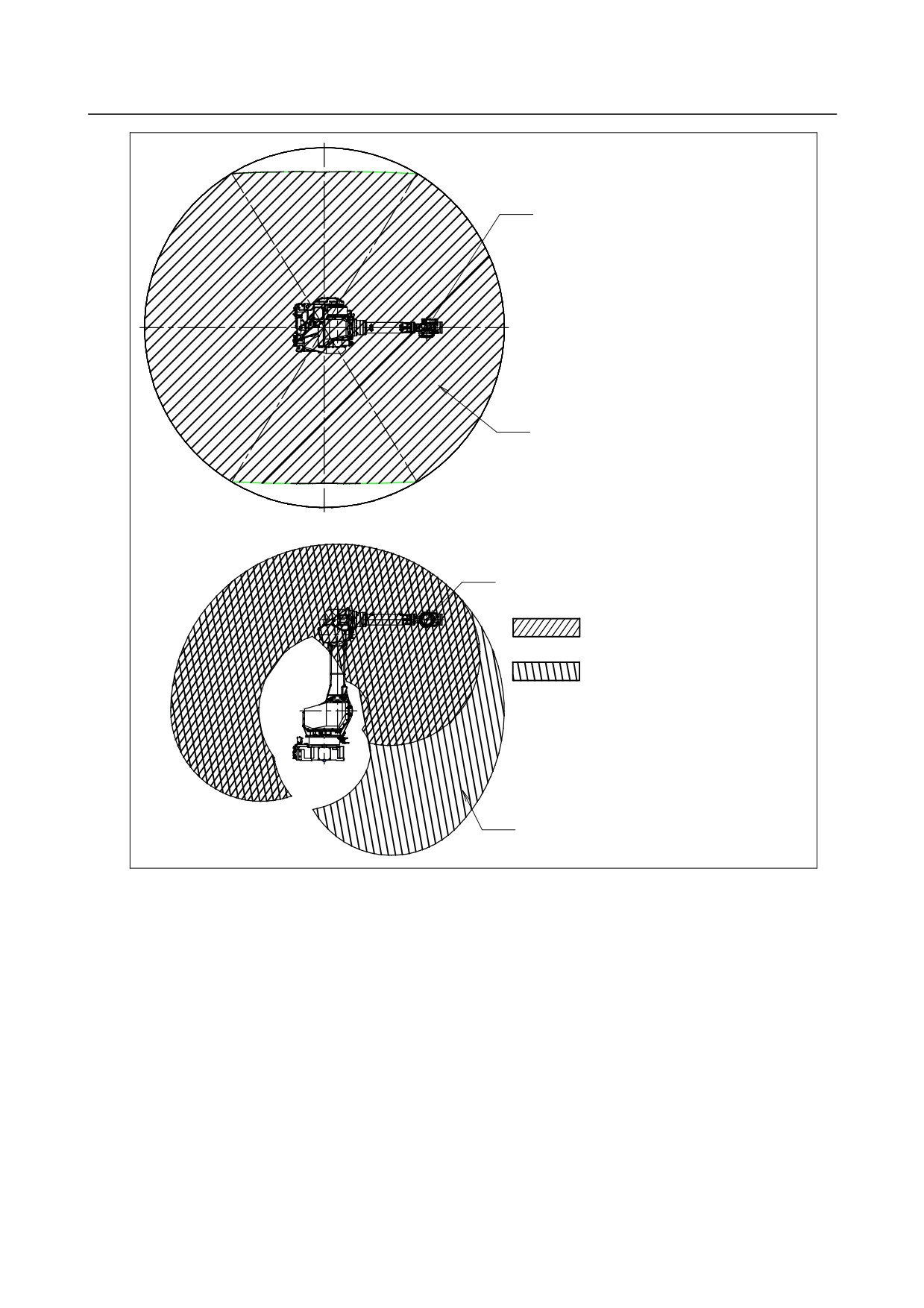
When robots are mounted on wall or inclined surface, the motion range has restricted range depending on
its mounted angle.
Fig.3.6 (a) to (l) show motion range for robots mounted on wall or inclined surface depending on its
mounted angle.
- 31 -
3.BASIC SPECIFICATIONS
B-82274EN/09
Mounted angle range(3)
Mounted angle range(2)
60°
120°
Mounted angle range(2)
45°
135°
Mounted angle range(1)
Mounted angle range(1)
O°
Fig.3.6 (a) Mounted angle (M-710iC/50, /50E)
J5-axis rotation center
Motion range of
J5-axis rotation center
J5-axis rotation center
Motion range of
J5-axis rotation center
Fig.3.6 (b) Motion range for mounted angle range (1) (M-710iC/50, /50E)
- 32 -
B-82274EN/09
3.BASIC SPECIFICATIONS
127(deg)
53(deg)
J5-axis rotation center
Motion range of
-127(deg)
-53(deg)
J5-axis rotation center
J5-axis rotation center
Range of motion when J1=±90(deg)
Range of motion when
-180(deg)≦J1≦-127(deg)
-53(deg)≦J1≦
53(deg)
127(deg)≦J1≦ 180(deg)
Motion range of
J5-axis rotation center
Fig.3.6 (c) Motion range for mounted angle range (2) (M-710iC/50, /50E)
- 33 -
3.BASIC SPECIFICATIONS
B-82274EN/09
136(deg)
44(deg)
J5-axis rotation center
Motion range of
J5-axis rotation center
-136(deg)
-44(deg)
J5-axis rotation center
Range of motion when J1=±90(deg)
Range of motion when
-180(deg)≦J1≦-136(deg)
-44(deg)≦J1≦
44(deg)
136(deg)≦J1≦ 180(deg)
Motion range of
J5-axis roation center
Fig.3.6 (d) Motion range for mounted angle range (3) (M-710iC/50, 50E)
Mounted angle range(4)
Mounted angle range(3)
60°
120°
Mounted angle range(3)
Mounted angle range(2)
Mounted angle range(2)
45°
135°
Mounted angle range(1)
35°
145°
Mounted angle range(1)
0°
Fig.3.6 (e) Mounted angle (M-710iC/70)
- 34 -
B-82274EN/09
3.BASIC SPECIFICATIONS
J5-axis rotatoin center
Motion range of
J5-axis rotation center
J5-axis rotation center
Motion range of
J5-axis rotation center
Fig.3.6 (f) Motion range for mounted angle range (1) (M-710iC/70)
- 35 -
3.BASIC SPECIFICATIONS
B-82274EN/09
121(deg)
59(deg)
J5-axis rotation center
Motion range of
J5-axis rotation center
-121(deg)
-59(deg)
J5-axis rotation center
Range of motion when J1=±90(deg)
Range of motion when
-180(deg)≦J1≦-121(deg)
-59(deg)≦J1≦
59(deg)
121(deg)≦J1≦ 180(deg)
Motion range of
J5-axis rotation center
Fig.3.6 (g) Motion range for mounted angle range (2) (M-710iC/70)
- 36 -
B-82274EN/09
3.BASIC SPECIFICATIONS
136(deg)
44(deg)
J5-axis rotation center
Motion range of
J5-axis roation center
-136(deg)
-44(deg)
J5-axis rotation center
Range of motion when J1=±90(deg)
Range of motion when
-180(deg)≦J1≦-136(deg)
-44(deg)≦J1≦
44(deg)
136(deg)≦J1≦ 180(deg)
Motion range of
J5-axis rotation center
Fig.3.6 (h) Motion range for mounted angle range (3) (M-710iC/70)
- 37 -
3.BASIC SPECIFICATIONS
B-82274EN/09
143(deg)
37(deg)
J5-axis rotation center
Motion range of
J5-axis rotation center
-143(deg)
-37(deg)
J5-axis rotation center
Range of motion when J1=±90(deg)
Range of motion when
-180(deg)≦J1≦-143(deg)
-37(deg)≦J1≦
37(deg)
143(deg)≦J1≦ 180(deg)
Motion range of
J5-axis rotation center
Fig.3.6 (i) Motion range for mounted angle range (3) (M-710iC/70)
Mounted angle range(2)
Mounted angle range(1)
70°
110°
0°
Fig.3.6 (j) Mounted angle (M-710iC/50S)
- 38 -
B-82274EN/09
3.BASIC SPECIFICATIONS
J5-axis rotation center
Motion range of
J5-axis rotation center
J5-axis rotation center
Motion range of
J5-axis rotation center
Fig.3.6 (k) Motion range for mounted angle range (1) (M-710iC/50S)
- 39 -