FANUC Robot M-710iC MECHANICAL UNIT. OPERATOR'S MANUAL (B-82274EN/09) - page 1
B-82274EN/09
SAFETY PRECAUTIONS
SAFETY PRECAUTIONS
Thank you for purchasing FANUC Robot.
This chapter describes the precautions which must be observed to ensure the safe use of the robot.
Before attempting to use the robot, be sure to read this chapter thoroughly.
Before using the functions related to robot operation, read the relevant operator's manual to become
familiar with those functions.
If any description in this chapter differs from that in the other part of this manual, the description given in
this chapter shall take precedence.
For the safety of the operator and the system, follow all safety precautions when operating a robot and its
peripheral devices installed in a work cell.
In addition, refer to the “FANUC Robot SAFETY HANDBOOK (B-80687EN)”.
1 WORKING PERSON
The personnel can be classified as follows.
Operator:
• Turns robot controller power ON/OFF
• Starts robot program from operator’s panel
Programmer or teaching operator:
• Operates the robot
• Teaches robot inside the safety fence
Maintenance engineer:
• Operates the robot
• Teaches robot inside the safety fence
• Maintenance (adjustment, replacement)
-
An operator cannot work inside the safety fence.
-
A programmer, teaching operator, and maintenance engineer can work inside the safety fence. The
working activities inside the safety fence include lifting, setting, teaching, adjusting, maintenance,
etc..
-
To work inside the fence, the person must be trained on proper robot operation.
During the operation, programming, and maintenance of your robotic system, the programmer, teaching
operator, and maintenance engineer should take additional care of their safety by using the following
safety precautions.
-
Use adequate clothing or uniforms during system operation
-
Wear safety shoes
-
Use helmet
s-1
SAFETY PRECAUTIONS
B-82274EN/09
2 DEFINITION OF WARNING, CAUTION AND
NOTE
To ensure the safety of user and prevent damage to the machine, this manual indicates each precaution on
safety with "Warning" or "Caution" according to its severity. Supplementary information is indicated by
"Note". Read the contents of each "Warning", "Caution" and "Note" before attempting to use the
oscillator.
WARNING
Applied when there is a danger of the user being injured or when there is a
danger of both the user being injured and the equipment being damaged if the
approved procedure is not observed.
CAUTION
Applied when there is a danger of the equipment being damaged, if the
approved procedure is not observed.
NOTE
Notes are used to indicate supplementary information other than Warnings and
Cautions.
• Read this manual carefully, and store it in a sales place.
3 WORKING PERSON SAFETY
Working person safety is the primary safety consideration. Because it is very dangerous to enter the
operating space of the robot during automatic operation, adequate safety precautions must be observed.
The following lists the general safety precautions. Careful consideration must be made to ensure
working person safety.
(1) Have the robot system working persons attend the training courses held by FANUC.
FANUC provides various training courses. Contact our sales office for details.
(2) Even when the robot is stationary, it is possible that the robot is still in a ready to move state, and is
waiting for a signal. In this state, the robot is regarded as still in motion. To ensure working
person safety, provide the system with an alarm to indicate visually or aurally that the robot is in
motion.
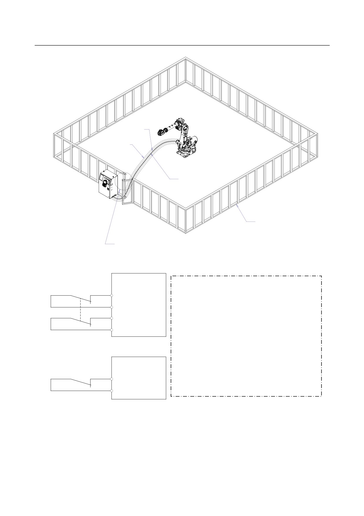
(3) Install a safety fence with a gate so that no working person can enter the work area without passing
through the gate. Install an interlocking device, a safety plug, and so forth in the safety gate so that
the robot is stopped as the safety gate is opened.
The controller is designed to receive this interlocking signal of the door switch. When the gate
is opened and this signal received, the controller stops the robot (Please refer to "STOP
TYPE OF ROBOT" in SAFETY PRECAUTIONS for detail of stop type). For connection, see
Fig.3 (a) and Fig.3 (b).
(4) Provide the peripheral devices with appropriate grounding (Class A, Class B, Class C, and Class D).
s-2
B-82274EN/09
SAFETY PRECAUTIONS
(5) Try to install the peripheral devices outside the work area.
(6) Draw an outline on the floor, clearly indicating the range of the robot motion, including the tools
such as a hand.
(7) Install a mat switch or photoelectric switch on the floor with an interlock to a visual or aural alarm
that stops the robot when a working person enters the work area.
(8) If necessary, install a safety lock so that no one except the working person in charge can turn on the
power of the robot.
The circuit breaker installed in the controller is designed to disable anyone from turning it on
when it is locked with a padlock.
(9) When adjusting each peripheral device independently, be sure to turn off the power of the robot
(10) Operators should be ungloved while manipulating the operator’s panel or teach pendant. Operation
with gloved fingers could cause an operation error.
(11) Programs, system variables, and other information can be saved on memory card or USB memories.
Be sure to save the data periodically in case the data is lost in an accident.
(12) The robot should be transported and installed by accurately following the procedures recommended
by FANUC. Wrong transportation or installation may cause the robot to fall, resulting in severe
injury to workers.
(13) In the first operation of the robot after installation, the operation should be restricted to low speeds.
Then, the speed should be gradually increased to check the operation of the robot.
(14) Before the robot is started, it should be checked that no one is in the area of the safety fence. At the
same time, a check must be made to ensure that there is no risk of hazardous situations. If detected,
such a situation should be eliminated before the operation.
(15) When the robot is used, the following precautions should be taken. Otherwise, the robot and
peripheral equipment can be adversely affected, or workers can be severely injured.
- Avoid using the robot in a flammable environment.
- Avoid using the robot in an explosive environment.
- Avoid using the robot in an environment full of radiation.
- Avoid using the robot under water or at high humidity.
- Avoid using the robot to carry a person or animal.
- Avoid using the robot as a stepladder. (Never climb up on or hang from the robot.)
(16) When connecting the peripheral devices related to stop(safety fence etc.) and each signal (external
emergency , fence etc.) of robot. be sure to confirm the stop movement and do not take the wrong
connection.
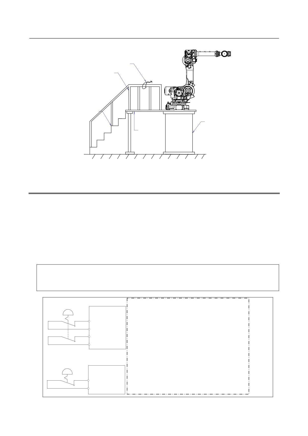
(17) When preparing trestle, please consider security for installation and maintenance work in high place
according to Fig.3 (c). Please consider footstep and safety bolt mounting position.
s-3
SAFETY PRECAUTIONS
B-82274EN/09
RP1
Pulsecoder
RI/RO,XHBK,XROT
RM1
Motor power/brake
EARTH
Safety fence
Interlocking device and safety plug that are activated if the
gate is opened.
Fig. 3 (a) Safety fence and safety gate
Dual chain
Emergency stop board
(Note)
or Panel board
EAS1
In case of R-30iB
Terminals EAS1,EAS11,EAS2,EAS21 are provided on the
EAS11
emergency stop board.
EAS2
In case R-30iA
EAS21
Terminals EAS1,EAS11,EAS2,EAS21 are provided on the
emergency stop board or connector panel
In case R-30iA Mate
Terminals EAS1,EAS11,EAS2,EAS21 or FENCE1,FENCE2
Single chain
are provided on the emergency stop board or in the connector
Panel board
panel of CRM65 (Open air type).
FENCE1
Refer to the ELECTRICAL CONNCETIONS Chapter of
FENCE2
CONNECTION of controller maintenance manual for details.
Fig. 3 (b) Limit switch circuit diagram of the safety fence
s-4
B-82274EN/09
SAFETY PRECAUTIONS
Hook for safety belt
Fence
Steps
Trestle
Footstep
for maintenance
Fig.3 (c) Footstep for maintenance
3.1
OPERATOR SAFETY
The operator is a person who operates the robot system. In this sense, a worker who operates the teach
pendant is also an operator. However, this section does not apply to teach pendant operators.
(1) If you do not have to operate the robot, turn off the power of the robot controller or press the
EMERGENCY STOP button, and then proceed with necessary work.
(2) Operate the robot system at a location outside of the safety fence
(3) Install a safety fence with a safety gate to prevent any worker other than the operator from entering
the work area unexpectedly and to prevent the worker from entering a dangerous area.
(4) Install an EMERGENCY STOP button within the operator’s reach.
The robot controller is designed to be connected to an external EMERGENCY STOP button.
With this connection, the controller stops the robot operation (Please refer to "STOP TYPE
OF ROBOT" in SAFETY PRECAUTIONS for detail of stop type), when the external
EMERGENCY STOP button is pressed. See the diagram below for connection.
Dual chain
(Note)
External stop button
Connect EES1 and EES11, EES2 and EES21 or EMGIN1
Emergency stop board
and EMGIN2
or Panel board
EES1
In case R-30iB
EES1,EES11,EES2,EES21 are on the emergency stop board
EES11
EES2
In case R-30iA
EES1,EES11,EES2,EES21 or EMGIN1, EMGIN2 are on the
EES21
panel board.
In case R-30iA Mate
Single chain
Terminals EAS1,EAS11,EAS2,EAS21 or FENCE1,FENCE2
External stop button
are provided on the emergency stop board or in the connector
Panel board
panel of CRM65 (Open air type).
EMGIN1
Refer to the ELECTRICAL CONNCETIONS Chapter of
EMGIN2
CONNECTION of controller maintenance manual for details.
Fig.3.1 Connection diagram for external emergency stop button
s-5
SAFETY PRECAUTIONS
B-82274EN/09
3.2
SAFETY OF THE PROGRAMMER
While teaching the robot, the operator must enter the work area of the robot. The operator must ensure
the safety of the teach pendant operator especially.
(1) Unless it is specifically necessary to enter the robot work area, carry out all tasks outside the area.
(2) Before teaching the robot, check that the robot and its peripheral devices are all in the normal
operating condition.
(3) If it is inevitable to enter the robot work area to teach the robot, check the locations, settings, and
other conditions of the safety devices (such as the EMERGENCY STOP button, the DEADMAN
switch on the teach pendant) before entering the area.
(4) The programmer must be extremely careful not to let anyone else enter the robot work area.
(5) Programming should be done outside the area of the safety fence as far as possible. If programming
needs to be done in the area of the safety fence, the programmer should take the following
precautions:
- Before entering the area of the safety fence, ensure that there is no risk of dangerous situations
in the area.
- Be prepared to press the emergency stop button whenever necessary.
- Robot motions should be made at low speeds.
- Before starting programming, check the entire system status to ensure that no remote instruction
to the peripheral equipment or motion would be dangerous to the user.
Our operator panel is provided with an emergency stop button and a key switch (mode switch) for selecting the
automatic operation mode (AUTO) and the teach modes (T1 and T2). Before entering the inside of the safety
fence for the purpose of teaching, set the switch to a teach mode, remove the key from the mode switch to prevent
other people from changing the operation mode carelessly, then open the safety gate. If the safety gate is opened
with the automatic operation mode set, the robot stops (Please refer to "STOP TYPE OF ROBOT" in SAFETY
PRECAUTIONS for detail of stop type). After the switch is set to a teach mode, the safety gate is disabled. The
programmer should understand that the safety gate is disabled and is responsible for keeping other people from
entering the inside of the safety fence. (In case of R-30iA Mate Controller standard specification, there is no mode
switch. The automatic operation mode and the teach mode is selected by teach pendant enable switch.)
Our teach pendant is provided with a DEADMAN switch as well as an emergency stop button. These button and
switch function as follows:
(1) Emergency stop button: Causes an emergency stop (Please refer to "STOP TYPE OF ROBOT" in SAFETY
PRECAUTIONS for detail of stop type) when pressed.
(2) DEADMAN switch: Functions differently depending on the teach pendant enable/disable switch setting
status.
(a)
Disable: The DEADMAN switch is disabled.
(b)
Enable: Servo power is turned off when the operator releases the DEADMAN switch or when the
operator presses the switch strongly.
Note) The DEADMAN switch is provided to stop the robot when the operator releases the teach pendant or
presses the pendant strongly in case of emergency. The R-30iB/R-30iA/ R-30iA Mate employs a
3-position DEADMAN switch, which allows the robot to operate when the 3-position DEADMAN switch is
pressed to its intermediate point. When the operator releases the DEADMAN switch or presses the
switch strongly, the robot stops immediately.
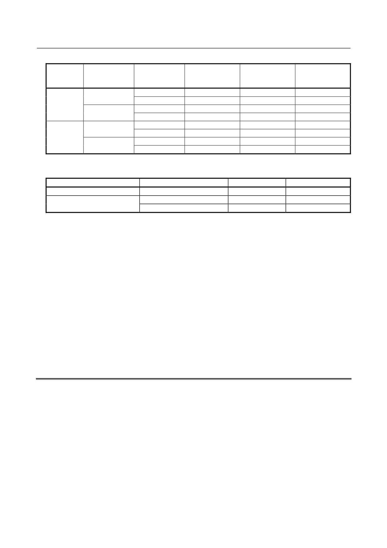
The operator’s intention of starting teaching is determined by the controller through the dual operation of setting the
teach pendant enable/disable switch to the enable position and pressing the DEADMAN switch. The operator
should make sure that the robot could operate in such conditions and be responsible in carrying out tasks safely.
The teach pendant, operator panel, and peripheral device interface send each robot start signal. However the
validity of each signal changes as follows depending on the mode switch and the DEADMAN switch of the operator
panel, the teach pendant enable switch and the remote condition on the software.
s-6
B-82274EN/09
SAFETY PRECAUTIONS
In case of R-30iB/R-30iA controller or CE or RIA specification of R-30iA Mate controller
Software
Teach pendant
Mode
remote
Teach pendant
Operator panel
Peripheral device
enable switch
condition
Local
Not allowed
Not allowed
Not allowed
On
AUTO
Remote
Not allowed
Not allowed
Not allowed
mode
Local
Not allowed
Allowed to start
Not allowed
Off
Remote
Not allowed
Not allowed
Allowed to start
Local
Allowed to start
Not allowed
Not allowed
On
T1, T2
Remote
Allowed to start
Not allowed
Not allowed
mode
Local
Not allowed
Not allowed
Not allowed
Off
Remote
Not allowed
Not allowed
Not allowed
T1,T2 mode: DEADMAN switch is effective.
In case of standard specification of R-30iA Mate controller
Teach pendant enable switch
Software remote condition
Teach pendant
Peripheral device
On
Ignored
Allowed to start
Not allowed
Off
Local
Not allowed
Not allowed
Remote
Not allowed
Allowed to start
(6)
(Only when R-30iB/R-30iA Controller or CE or RIA specification of R-30iA Mate controller is
selected.) To start the system using the operator’s panel, make certain that nobody is the robot work
area and that there are no abnormal conditions in the robot work area.
(7) When a program is completed, be sure to carry out a test operation according to the procedure
below.
(a) Run the program for at least one operation cycle in the single step mode at low speed.
(b) Run the program for at least one operation cycle in the continuous operation mode at low
speed.
(c) Run the program for one operation cycle in the continuous operation mode at the intermediate
speed and check that no abnormalities occur due to a delay in timing.
(d) Run the program for one operation cycle in the continuous operation mode at the normal
operating speed and check that the system operates automatically without trouble.
(e) After checking the completeness of the program through the test operation above, execute it in
the automatic operation mode.
(8) While operating the system in the automatic operation mode, the teach pendant operator should
leave the robot work area.
3.3
SAFETY OF THE MAINTENANCE ENGINEER
For the safety of maintenance engineer personnel, pay utmost attention to the following.
(1) During operation, never enter the robot work area.
(2) A hazardous situation may arise when the robot or the system, are kept with their power-on during
maintenance operations. Therefore, for any maintenance operation, the robot and the system should
be put into the power-off state. If necessary, a lock should be in place in order to prevent any other
person from turning on the robot and/or the system. In case maintenance needs to be executed in the
power-on state, the emergency stop button must be pressed.
(3) If it becomes necessary to enter the robot operation range while the power is on, press the
emergency stop button on the operator panel, or the teach pendant before entering the range. The
maintenance personnel must indicate that maintenance work is in progress and be careful not to
allow other people to operate the robot carelessly.
(4) When entering the area enclosed by the safety fence, the maintenance worker must check the entire
system in order to make sure no dangerous situations exist. In case the worker needs to enter the
s-7
SAFETY PRECAUTIONS
B-82274EN/09
safety area whilst a dangerous situation exists, extreme care must be taken, and entire system status
must be carefully monitored.
(5) Before the maintenance of the pneumatic system is started, the supply pressure should be shut off
and the pressure in the piping should be reduced to zero.
(6) Before the start of teaching, check that the robot and its peripheral devices are all in the normal
operating condition.
(7) Do not operate the robot in the automatic mode while anybody is in the robot work area.
(8) When you maintain the robot alongside a wall or instrument, or when multiple workers are working
nearby, make certain that their escape path is not obstructed.
(9) When a tool is mounted on the robot, or when any moving device other than the robot is installed,
such as belt conveyor, pay careful attention to its motion.
(10) If necessary, have a worker who is familiar with the robot system stand beside the operator panel
and observe the work being performed. If any danger arises, the worker should be ready to press
the EMERGENCY STOP button at any time.
(11) When replacing a part, please contact FANUC service center. If a wrong procedure is followed, an
accident may occur, causing damage to the robot and injury to the worker.
(12) When replacing or reinstalling components, take care to prevent foreign matter from entering the
system.
(13) When handling each unit or printed circuit board in the controller during inspection, turn off the
circuit breaker to protect against electric shock.
If there are two cabinets, turn off the both circuit breaker.
(14) A part should be replaced with a part recommended by FANUC. If other parts are used, malfunction
or damage would occur. Especially, a fuse that is not recommended by FANUC should not be used.
Such a fuse may cause a fire.
(15) When restarting the robot system after completing maintenance work, make sure in advance that
there is no person in the work area and that the robot and the peripheral devices are not abnormal.
(16) When a motor or brake is removed, the robot arm should be supported with a crane or other
equipment beforehand so that the arm would not fall during the removal.
(17) Whenever grease is spilled on the floor, it should be removed as quickly as possible to prevent
dangerous falls.
(18) The following parts are heated. If a maintenance worker needs to touch such a part in the heated
state, the worker should wear heat-resistant gloves or use other protective tools.
- Servo motor
- Inside the controller
- Reducer
- Gearbox
- Wrist unit
(19) Maintenance should be done under suitable light. Care must be taken that the light would not cause
any danger.
(20) When a motor, reducer, or other heavy load is handled, a crane or other equipment should be used to
protect maintenance workers from excessive load. Otherwise, the maintenance workers would be
severely injured.
(21) The robot should not be stepped on or climbed up during maintenance. If it is attempted, the robot
would be adversely affected. In addition, a misstep can cause injury to the worker.
(22)When performing maintenance work in high place, secure a footstep and wear safety belt.
(23) After the maintenance is completed, spilled oil or water and metal chips should be removed from the
floor around the robot and within the safety fence.
(24) When a part is replaced, all bolts and other related components should put back into their original
places. A careful check must be given to ensure that no components are missing or left not mounted.
(25) In case robot motion is required during maintenance, the following precautions should be taken :
- Foresee an escape route. And during the maintenance motion itself, monitor continuously the
whole system so that your escape route will not become blocked by the robot, or by peripheral
equipment.
- Always pay attention to potentially dangerous situations, and be prepared to press the emergency
s-8
B-82274EN/09
SAFETY PRECAUTIONS
stop button whenever necessary.
(26) The robot should be periodically inspected. (Refer to the robot mechanical manual and controller
maintenance manual.) A failure to do the periodical inspection can adversely affect the performance
or service life of the robot and may cause an accident
(27) After a part is replaced, a test operation should be given for the robot according to a predetermined
method. (See TESTING section of “Controller operator’s manual”.) During the test execution, the
maintenance staff should work outside the safety fence.
4 SAFETY OF THE TOOLS AND
PERIPHERAL DEVICES
4.1
PRECAUTIONS IN PROGRAMMING
(1) Use a limit switch or other sensor to detect a dangerous condition and, if necessary, design the
program to stop the robot when the sensor signal is received.
(2) Design the program to stop the robot when an abnormal condition occurs in any other robots or
peripheral devices, even though the robot itself is normal.
(3) For a system in which the robot and its peripheral devices are in synchronous motion, particular care
must be taken in programming so that they do not interfere with each other.
(4) Provide a suitable interface between the robot and its peripheral devices so that the robot can detect
the states of all devices in the system and can be stopped according to the states.
4.2
PRECAUTIONS FOR MECHANISM
(1)
Keep the component cells of the robot system clean, and operate the robot in an environment free of
grease, water, and dust.
(2)
Don’t use unconfirmed liquid for cutting fluid and cleaning fluid.
(3)
Employ a limit switch or mechanical stopper to limit the robot motion so that the robot or cable does
not strike against its peripheral devices or tools.
(4)
Observe the following precautions about the mechanical unit cables. When theses attentions are not
kept, unexpected troubles might occur.
•
Use mechanical unit cable that have required user interface.
•
Don’t add user cable or hose to inside of mechanical unit.
•
Please do not obstruct the movement of the mechanical unit cable when cables are added to
outside of mechanical unit.
•
In the case of the model that a cable is exposed, Please do not perform remodeling (Adding a
protective cover and fix an outside cable more) obstructing the behavior of the outcrop of the
cable.
•
Please do not interfere with the other parts of mechanical unit when install equipments in the
robot.
(5)
The frequent power-off stop for the robot during operation causes the trouble of the robot. Please
avoid the system construction that power-off stop would be operated routinely. (Refer to bad case
example.) Please execute power-off stop after reducing the speed of the robot and stopping it by
hold stop or cycle stop when it is not urgent. (Please refer to "STOP TYPE OF ROBOT" in
SAFETY PRECAUTIONS for detail of stop type.)
(Bad case example)
•
Whenever poor product is generated, a line stops by emergency stop.
•
When alteration was necessary, safety switch is operated by opening safety fence and
power-off stop is executed for the robot during operation.
•
An operator pushes the emergency stop button frequently, and a line stops.
s-9
SAFETY PRECAUTIONS
B-82274EN/09
•
An area sensor or a mat switch connected to safety signal operate routinely and power-off stop
is executed for the robot.
(6) Robot stops urgently when collision detection alarm (SRVO-050) etc. occurs. The frequent urgent
stop by alarm causes the trouble of the robot, too. So remove the causes of the alarm.
5 SAFETY OF THE ROBOT MECHANISM
5.1
PRECAUTIONS IN OPERATION
(1) When operating the robot in the jog mode, set it at an appropriate speed so that the operator can
manage the robot in any eventuality.
(2) Before pressing the jog key, be sure you know in advance what motion the robot will perform in the
jog mode.
5.2
PRECAUTIONS IN PROGRAMMING
(1) When the work areas of robots overlap, make certain that the motions of the robots do not interfere
with each other.
(2) Be sure to specify the predetermined work origin in a motion program for the robot and program the
motion so that it starts from the origin and terminates at the origin.
Make it possible for the operator to easily distinguish at a glance that the robot motion has
terminated.
5.3
PRECAUTIONS FOR MECHANISMS
(1) Keep the work areas of the robot clean, and operate the robot in an environment free of grease, water,
and dust.
5.4
PROCEDURE TO MOVE ARM WITHOUT DRIVE POWER
IN EMERGENCY OR ABNORMAL SITUATIONS
(1) For emergency or abnormal situations (e.g. persons trapped in or by the robot), brake release unit
can be used to move the robot axes without drive power.
Please order following unit and cable.
Name
Specification
A05B-2450-J350
(Input voltage AC100-115V single phase)
Brake release unit
A05B-2450-J351
(Input voltage AC200-240V single phase)
A05B-2450-J360
(5m)
Robot connection cable
A05B-2450-J361
(10m)
A05B-2525-J010
(5m) (AC100-115V Power plug) (*)
A05B-2525-J011
(10m) (AC100-115V Power plug) (*)
Power cable
A05B-2450-J364
(5m) (No power plug)
A05B-2450-J365
(10m) (No power plug)
(*) These do not support CE marking.
(2) Please make sure that adequate numbers of brake release units are available and readily accessible
for robot system before installation.
(3) Regarding how to use brake release unit, please refer to Robot controller maintenance manual.
s-10
B-82274EN/09
SAFETY PRECAUTIONS
NOTE
Robot systems installed without adequate number of brake release units or
similar means are not in compliance with EN ISO 10218-1 and the Machinery
Directive and therefore cannot bear the CE marking.
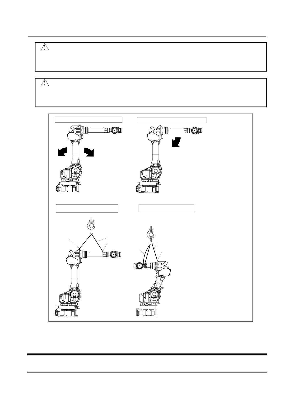
CAUTION
Robot arm would fall down by releasing its brake because of gravity. Therefore,
it is strongly recommended to take adequate measures such as hanging Robot
arm by a crane before releasing a brake.
In case of releasing J2-axis motor brake
In case of releasing J3-axis motor brake
Fall down
Fall down
Fall down
Method of supporting Robot Arm
Method of supporting Robot Arm
(M-710iC/50, /70, /50H, /50E)
(M-710iC/50S)
Slings
Eyebolt(M8)
Eyebolt(M8)
Slings
Slings
Eyebolt(M8)
This figure is example of floor mount.
(*)
The direction of fall is different
according to the installation angle,so
please support robot appropriately in
consideration of the influence of gravity.
Fig. 5.4 Releasing J2 and J3 motor brake and measures
6 SAFETY OF THE END EFFECTOR
6.1
PRECAUTIONS IN PROGRAMMING
(1) To control the pneumatic, hydraulic and electric actuators, carefully consider the necessary time
delay after issuing each control command up to actual motion and ensure safe control.
s-11
SAFETY PRECAUTIONS
B-82274EN/09
(2) Provide the end effector with a limit switch, and control the robot system by monitoring the state of
the end effector.
7 STOP TYPE OF ROBOT
The following three robot stop types exist:
Power-Off Stop (Category 0 following IEC 60204-1)
Servo power is turned off and the robot stops immediately. Servo power is turned off when the robot is
moving, and the motion path of the deceleration is uncontrolled.
The following processing is performed at Power-Off stop.
-
An alarm is generated and servo power is turned off.
-
The robot operation is stopped immediately. Execution of the program is paused.
Controlled stop (Category 1 following IEC 60204-1)
The robot is decelerated until it stops, and servo power is turned off.
The following processing is performed at Controlled stop.
-
The alarm "SRVO-199 Controlled stop" occurs along with a decelerated stop. Execution of the
program is paused.
-
An alarm is generated and servo power is turned off.
Hold (Category 2 following IEC 60204-1)
The robot is decelerated until it stops, and servo power remains on.
The following processing is performed at Hold.
-
The robot operation is decelerated until it stops. Execution of the program is paused.
WARNING
The stopping distance and stopping time of Controlled stop are longer than the
stopping distance and stopping time of Power-Off stop. A risk assessment for
the whole robot system, which takes into consideration the increased stopping
distance and stopping time, is necessary when Controlled stop is used.
When the emergency stop button is pressed or the FENCE is open, the stop type of robot is Power-Off
stop or Controlled stop. The configuration of stop type for each situation is called stop pattern. The stop
pattern is different according to the controller type or option configuration.
There are the following 3 Stop patterns.
Emergency
External
Stop
Servo
Mode
stop
Emergency
FENCE open
SVOFF input
pattern
disconnect
button
stop
AUTO
P-Stop
P-Stop
C-Stop
C-Stop
P-Stop
A
T1
P-Stop
P-Stop
-
C-Stop
P-Stop
T2
P-Stop
P-Stop
-
C-Stop
P-Stop
AUTO
P-Stop
P-Stop
P-Stop
P-Stop
P-Stop
B
T1
P-Stop
P-Stop
-
P-Stop
P-Stop
T2
P-Stop
P-Stop
-
P-Stop
P-Stop
AUTO
C-Stop
C-Stop
C-Stop
C-Stop
C-Stop
C
T1
P-Stop
P-Stop
-
C-Stop
P-Stop
T2
P-Stop
P-Stop
-
C-Stop
P-Stop
P-Stop: Power-Off stop
C-Stop: Controlled stop
s-12
B-82274EN/09
SAFETY PRECAUTIONS
-:
Disable
The following table indicates the Stop pattern according to the controller type or option configuration.
Option
R-30iB
Standard
A (*)
Controlled stop by E-Stop
(A05B-2600-J570)
C (*)
(*) R-30iB does not have servo disconnect.
R-30iA
R-30iA Mate
Option
Standard
Standard
RIA
CE
RIA
CE
Standard
(Single)
(Dual)
type
type
type
type
Standard
B (*)
A
A
A
A (**)
A
A
Stop type set (Stop pattern C)
N/A
N/A
C
C
N/A
C
C
(A05B-2500-J570)
(*) R-30iA standard (single) does not have servo disconnect.
(**) R-30iA Mate Standard does not have servo disconnect, and the stop type of SVOFF input is
Power-Off stop.
The stop pattern of the controller is displayed in "Stop pattern" line in software version screen. Please
refer to "Software version" in operator's manual of controller for the detail of software version screen.
"Controlled stop by E-Stop" option
When "Controlled stop by E-Stop" (A05B-2600-J570) option (In case of R-30iA/R-30iA Mate, it is Stop
type set (Stop pattern C) (A05B-2500-J570)) is specified, the stop type of the following alarms becomes
Controlled stop but only in AUTO mode. In T1 or T2 mode, the stop type is Power-Off stop which is
the normal operation of the system.
Alarm
Condition
SRVO-001 Operator panel E-stop
Operator panel emergency stop is pressed.
SRVO-002 Teach pendant E-stop
Teach pendant emergency stop is pressed.
SRVO-007 External emergency stops
External emergency stop input (EES1-EES11, EES2-EES21) is
open. (R-30iA/R-30iB controller)
SRVO-194 Servo disconnect
Servo disconnect input (SD4-SD41, SD5-SD51) is open.
(R-30iA controller)
SRVO-218 Ext. E-stop/Servo Disconnect
External emergency stop input (EES1-EES11, EES2-EES21) is
open. (R-30iA Mate/R-30iB controller)
SRVO-408 DCS SSO Ext Emergency Stop
In DCS Safe I/O connect function, SSO[3] is OFF.
SRVO-409 DCS SSO Servo Disconnect
In DCS Safe I/O connect function, SSO[4] is OFF.
Controlled stop is different from Power-Off stop as follows:
-
In Controlled stop, the robot is stopped on the program path. This function is effective for a system
where the robot can interfere with other devices if it deviates from the program path.
-
In Controlled stop, physical impact is less than Power-Off stop. This function is effective for
systems where the physical impact to the mechanical unit or EOAT (End Of Arm Tool) should be
minimized.
-
The stopping distance and stopping time of Controlled stop is longer than the stopping distance and
stopping time of Power-Off stop, depending on the robot model and axis. Please refer to the
operator's manual of a particular robot model for the data of stopping distance and stopping time.
In case of R-30iA or R-30iA Mate, this function is available only in CE or RIA type hardware.
When this option is loaded, this function cannot be disabled.
The stop type of DCS Position and Speed Check functions is not affected by the loading of this option.
s-13
SAFETY PRECAUTIONS
B-82274EN/09
WARNING
The stopping distance and stopping time of Controlled stop are longer than the
stopping distance and stopping time of Power-Off stop. A risk assessment for
the whole robot system, which takes into consideration the increased stopping
distance and stopping time, is necessary when this option is loaded.
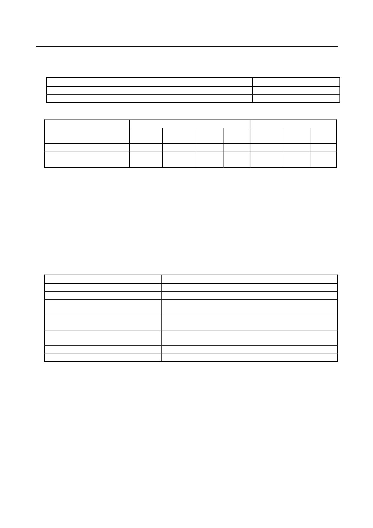
8 WARNING LABEL
(1) Greasing and degreasing label
1)
必ず排脂口を開けて給脂して下さい。
Open the grease outlet
at greasing.
必须在排脂口打开的状态下供脂。
2)
手動式ポンプを使用して給脂を行って
下さい。
Use a hand pump at
greasing.
请使用手动式供脂泵进行供脂。
3) 必ず指定グリスを使用して下さい。
Use designated grease
at greasing.
必须使用指定的润滑脂。
Fig. 8 (a) Greasing and degreasing label
Description
When greasing and degreasing, observe the instructions indicated on this label.
1)
When greasing, be sure to keep the grease outlet open.
2)
Use a manual pump to grease.
3)
Be sure to use specified grease.
CAUTION
See Chapter 7 CHECKS AND MAINTENANCE for explanations about specified
greases, the amount of grease to be supplied, and the locations of grease and
degrease outlets for individual models.
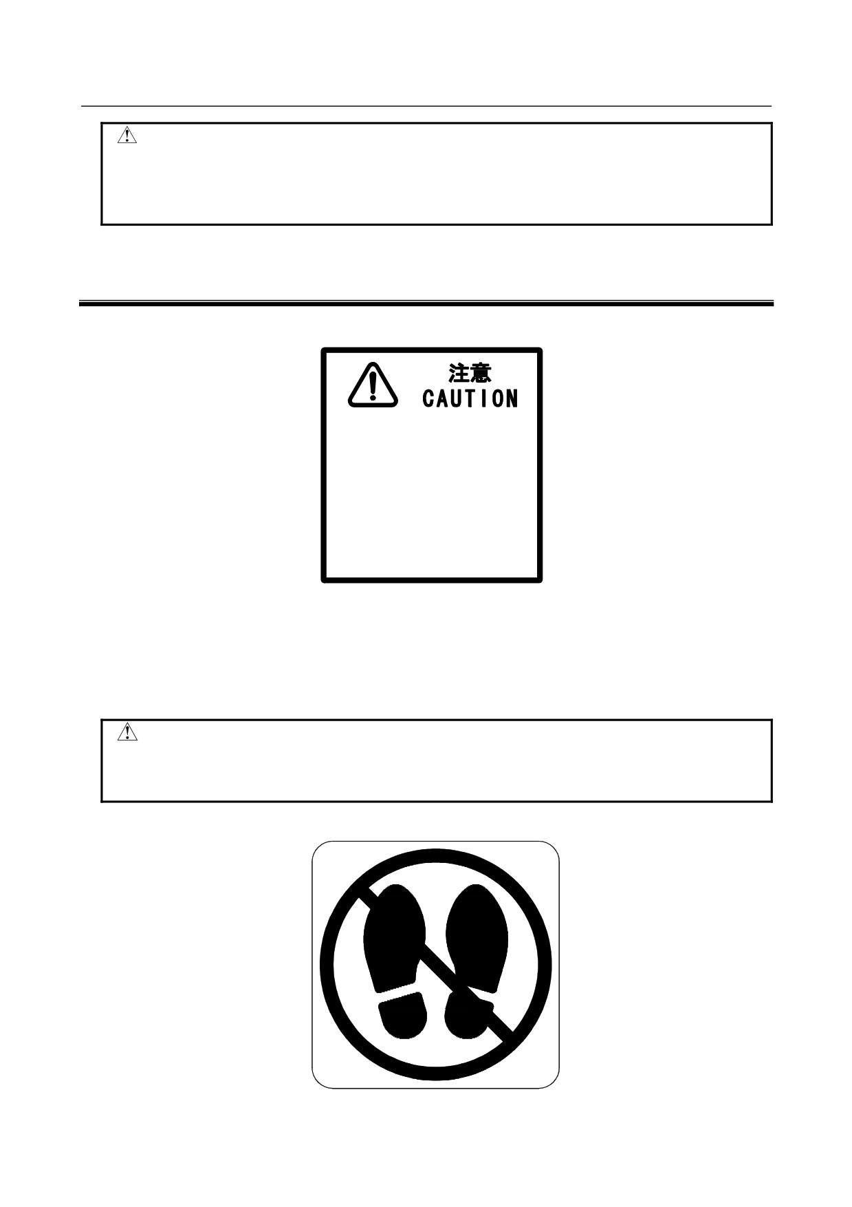
(2) Step-on prohibitive label
Fig. 8 (b) Step-on prohibitive label
s-14
B-82274EN/09
SAFETY PRECAUTIONS
Description
Do not step on or climb the robot or controller as it may adversely affect the robot or controller and you
may get hurt if you lose your footing as well.
(3) High-temperature warning label
Fig. 8 (c) Step-on prohibitive label
Description
Be cautious about a section where this label is affixed, as the section generates heat. If you have to
inevitably touch such a section when it is hot, use a protective provision such as heat-resistant gloves.
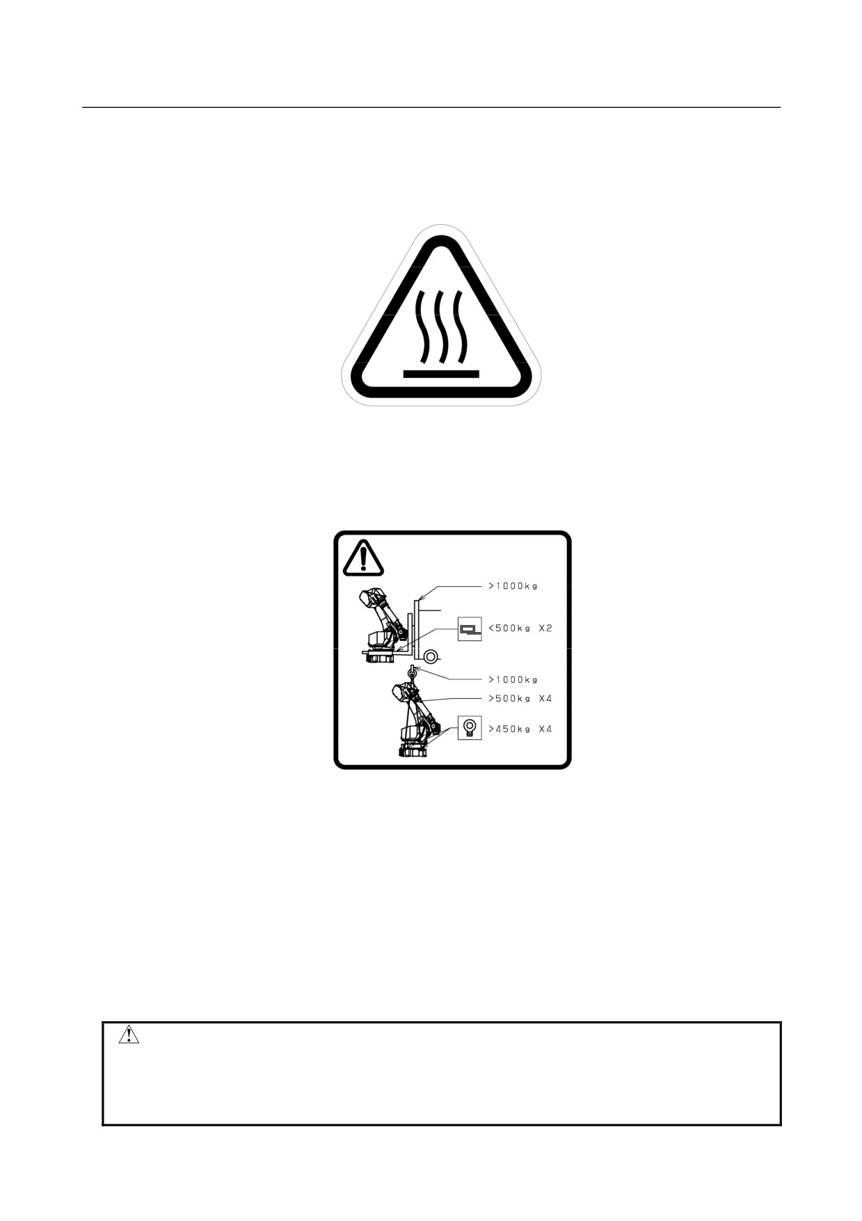
(4) Transportation label
Fig. 8 (d) Step-on prohibitive label
Description
When transporting the robot, observe the instructions indicated on this label.
1)
Using a forklift
•
Use a forklift having a load capacity of 1,000 kg or greater.
•
Keep the total weight of the robot to be transported to within 1,000 kg, because the withstand load of
the forklift bracket (option) is 4,900 N (500 kgf).
2)
Using a crane
•
Use a crane having a load capacity of 1,000 kg or greater.
•
Use at least four slings each having a withstand load of 4,900 N (500 kgf) or greater.
•
Use at least four eyebolts each having a withstand load of 4,410 N (450 kgf) or greater.
CAUTION
Transportation labels are model-specific. Before transporting the robot, see the
transportation label affixed to the J2 base side.
See Sub-section 1.1 TRANSPORTATION for explanations about the posture a
specific model should take when it is transported.
s-15
SAFETY PRECAUTIONS
B-82274EN/09
(5)
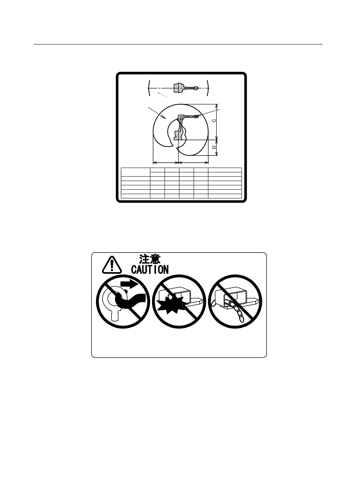
Range of motion and payload mark label
Below label is added when CE specification is specified.
+180deg.
0deg.
-180deg.
Motion range
J5-axis
of J5-axis
rotation
rotation center
center
J5轴旋转中心
J5轴旋转中心
动作范围
(M-710iC/50,
(M-710iC/50,50E,
50E,70,
70,50S,20L)
50S,20L)
Motion range
J4-axis
of J4-axis
rotation
rotation center
center
J4轴旋转中心
J4轴旋转中心
动作范围
(M-710iC/50H)
(M-710iC/50H)
B
A
A
B
C
D
MAX. PAYLOAD
(mm)
(mm)
(mm)
(mm)
(kg)
M-710iC/50,50E
2050
1750
2465
1080
50
M-710iC/70
2050
1750
2465
1080
70
M-710iC/50S
1359
962
1774
269
50
M-710iC/20L
3110
2810
3525
2058
20
M-710iC/50H
2003
1703
2418
1033
50
Fig. 8 (e) Range of motion and payload mark label
(6) Transportation prohibitive label
(When transport equipment option is specified.)
アイボルトを横引
輸送部材に衝撃を
輸送部材にチェーン
しないこと
与えないこと
などを掛けないこと
Do not pull eyebolt
Do not have impact
Do not chain, pry,
sideways
on this part
or strap on this part
禁止横向拉拽吊环螺钉
禁止撞击搬运用部件
禁止在搬运用部件上使用锁链
等物品固定或者搬运机器人
Fig. 8 (f) Transportation prohibitive label
Description
Keep the following in mind when transporting the robot.
1)
Do not pull eyebolts sideways
2)
Prevent the forks of the forklift from having impact on a transport equipment.
3)
Do not thread a chain or the like through a transport equipment.
s-16
B-82274EN/09
PREFACE
PREFACE
This manual explains the operation procedures for the mechanical units of the following robots:
Model name
Mechanical unit specification No.
Maximum load
FANUC Robot M-710iC/50
A05B-1125-B201
50kg
FANUC Robot M-710iC/70
A05B-1125-B202
70kg
FANUC Robot M-710iC/50H
A05B-1125-B204
50kg
FANUC Robot M-710iC/50S
A05B-1125-B207
50kg
FANUC Robot M-710iC/50E
A05B-1125-B251
50kg
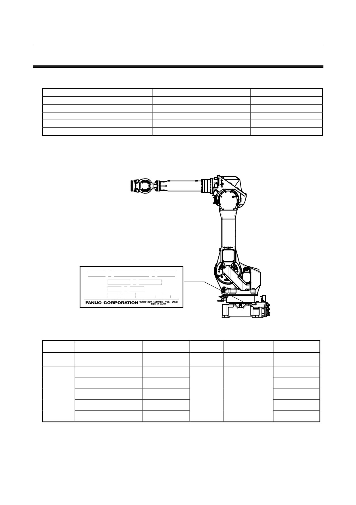
The label stating the mechanical unit specification number is affixed in the position shown below.
Before reading this manual, determine the specification number of the mechanical unit.
(1)
TYPE
(2)
NO.
(3)
WEIGHT
DATE
(4)
(5)
kg
TABLE 1)
(1)
(2)
(3)
(4)
(5)
WEIGHT kg
CONTENTS
-
TYPE
No.
DATE
(Without controller)
FANUC Robot M-710iC/50
A05B-1125-B201
560
FANUC Robot M-710iC/70
A05B-1125-B202
560
PRINT
PRINT
LETTERS
FANUC Robot M-710iC/50H
A05B-1125-B204
PRODUCTION
540
SERIAL NO.
YEAR AND MONTH
FANUC Robot M-710iC/50S
A05B-1125-B207
545
FANUC Robot M-710iC/50E
A05B-1125-B251
560
Position of label indicating mechanical unit specification number
p-1

PREFACE
B-82274EN/09
RELATED MANUALS
For the FANUC Robot series, the following manuals are available:
Safety handbook B-80687EN
Intended readers:
All persons who use the FANUC Robot and system
All persons who use FANUC Robot, system designer
designer must read and understand thoroughly this
Topics:
handbook
Safety items for robot system design, operation,
maintenance
R-30iA
Setup and Operations manual
Intended readers:
controller
Operator, programmer, maintenance person, system
SPOT TOOL+
designer
B-83124EN-1
Topics:
HANDLING TOOL
Robot functions, operations, programming, setup,
B-83124EN-2
interfaces, alarms
ARC TOOL
Use:
B-83124EN-3
Robot operation, teaching, system design
DISPENSE TOOL
B-83124EN-4
ALARM CODE LIST
B-83124EN-6
SERVO GUN FUNCTION
B-82634EN
Maintenance manual
Intended readers:
B-82595EN
Maintenance person, system designer
Topics:
B-82595EN-1
Installation, connection to peripheral equipment,
(For Europe)
maintenance
Use:
B-82595EN-2
Installation, start-up, connection, maintenance
(For RIA)
R-30iB
OPERATOR'S MANUAL (Basic
Intended readers :
controller
Function)
Operator, programmer, maintenance person, system
B-83284EN
designer
OPERATOR'S MANUAL
Topics :
(Alarm Code List)
Robot functions, operations, programming, setup,
B-83284EN-1
interfaces, alarms
Optional Function OPERATOR'S
Use :
MANUAL
Robot operation, teaching, system design
B-83284EN-2
Spot Welding Function
OPERATOR'S MANUAL
B-83284EN-4
Dispense Function
OPERATOR'S MANUAL
B-83284EN-5
Maintenance manual
Intended readers :
B-83195EN
Maintenance person, system designer
Topics :
Installation, connection to peripheral equipment,
maintenance
Use :
Installation, start-up, connection, maintenance
p-2
B-82274EN/09
TABLE OF CONTENTS
TABLE OF CONTENTS
SAFETY PRECAUTIONS
s-1
PREFACE
p-1
1
TRANSPORTATION AND INSTALLATION
1
1.1
TRANSPORTATION
1
1.1.1
Transportation with an End Effector Attached
5
1.2
INSTALLATION
6
1.2.1
Actual Installation Example
7
1.3
MAINTENANCE AREA
9
1.4
INSTALLATION SPECIFICATIONS
9
2
CONNECTION WITH THE CONTROLLER
10
2.1
CONNECTION WITH THE CONTROLLER
10
3
BASIC SPECIFICATIONS
11
3.1
ROBOT CONFIGURATION
11
3.2
MECHANICAL UNIT OPERATION AREA AND INTERFERENCE
AREA
16
3.3
ZERO POINT POSITION AND MOTION LIMIT
19
3.4
WRIST LOAD CONDITIONS
26
3.5
LOAD CONDITIONS ON J3 CASING
30
3.6
MOTION RANGE FOR WALL/INCLINED SURFACE MOUNTED
ROBOTS
31
4
MECHANICAL COUPLING TO THE ROBOT
41
4.1
MECHANICAL COUPLING OF END EFFECTOR TO WRIST
41
4.2
EQUIPMENT MOUNTING FACE
44
4.3
LOAD SETTING
46
5
PIPING AND WIRING TO THE END EFFECTOR
48
5.1
AIR SUPPLY (OPTION)
49
5.2
AIR PIPING (OPTION)
49
5.3
INTERFACE FOR OPTION CABLE (OPTION)
51
6
AXIS LIMIT SETUP
64
6.1
SOFTWARE SETTING
64
6.2
ADJUSTABLE MECHANICAL STOPPER AND LIMIT SWITCH
SETTING (OPTION)
65
6.3
CHANGING THE MOTION RANGE BY THE LIMIT SWITCH
(OPTION)
72
6.4
ADJUSTING LIMIT SWITCH (OPTION)
74
7
CHECKS AND MAINTENANCE
75
7.1
PERIODIC MAINTENANCE
75
7.1.1
Daily Checks
75
7.1.2
First 1-Month (320 hours operating) Check
77
c-1
TABLE OF CONTENTS
B-82274EN/09
7.1.3
First 3-month (960 hours) Checks
78
7.1.4
3-month (960 hours) Checks
79
7.1.5
1-year (3,840 hours) Checks
79
7.1.6
1.5-year (5,760 hours) Checks
81
7.1.7
3-year (11,520 hours) Checks
81
7.1.8
4-year (15,360 hours) Checks
81
7.2
MAINTENANCE
81
7.2.1
Replacing the Batteries (1.5 Years checks)
81
7.2.2
Replacing the Grease of the Drive Mechanism (3 years (11,520 hours)
checks)
83
7.2.3
Grease Replacement Procedure of the J1, J2, J3-Axis Reducer
84
7.2.4
Grease Replacement Procedure for the J4/J5/J6-Axis Gearbox (J4/J5-axis
gearbox)
87
7.2.5
Grease Replacement Procedure for the Wrist
88
7.2.6
Procedure for Releasing Remaining Pressure within the Grease Bath
89
7.3
STORAGE
90
8
MASTERING
91
8.1
GENERAL
91
8.2
RESETTING ALARMS AND PREPARING FOR MASTERING
92
8.3
ZERO POSITION MASTERING
93
8.4
QUICK MASTERING
95
8.5
SINGLE AXIS MASTERING
97
8.6
MASTERING DATA ENTRY
99
8.7
CHECKING THE MASTERING
101
9
TROUBLESHOOTING
103
9.1
OVERVIEW
103
9.2
FAILURES, CAUSES AND MEASURES
103
10
SEVERE DUST/LIQUID PROTECTION PACKAGE (OPTION)
110
10.1
OVERVIEW
110
10.2
SEVERE DUST/LIQUID PROTECTION CHARACTERISTICS
110
10.3
CONFIGURATION OF THE SEVERE DUST/LIQUID PROTECTION
PACKAGE
111
10.4
NOTES ON SPECIFYING SEVERE DUST/LIQUID PROTECTION
PACKAGE
112
11
CORRESPOND TO WASHING APPLICATION (OPTION)
113
11.1
ABOUT CORRESPOND TO WASHING APPLICATION
113
11.2
NOTES OF CORRESPOND TO WASHING APPLICATION
113
11.3
INSTALLING THE AIR PURGE KIT
114
12
MOTOR AIR BLOW OPPTION (OPTION)
116
APPENDIX
A PERIODIC MAINTENANCE TABLE
119
B STRENGTH OF BOLT AND BOLT TORQUE LIST
124
C INSULATION ABOUT ARC WELDING ROBOT
125
c-2
B-82274EN/09
TABLE OF CONTENTS
C.1
ABSTRACT
125
C.2
INSULATION AT THE WRIST
125
c-3
B-82274EN/09
1.TRANSPORTATION AND INSTALLATION
1 TRANSPORTATION AND INSTALLATION
1.1
TRANSPORTATION
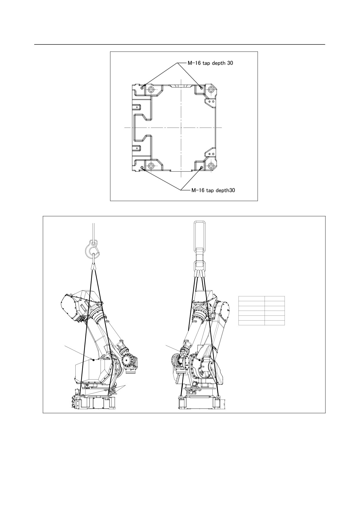
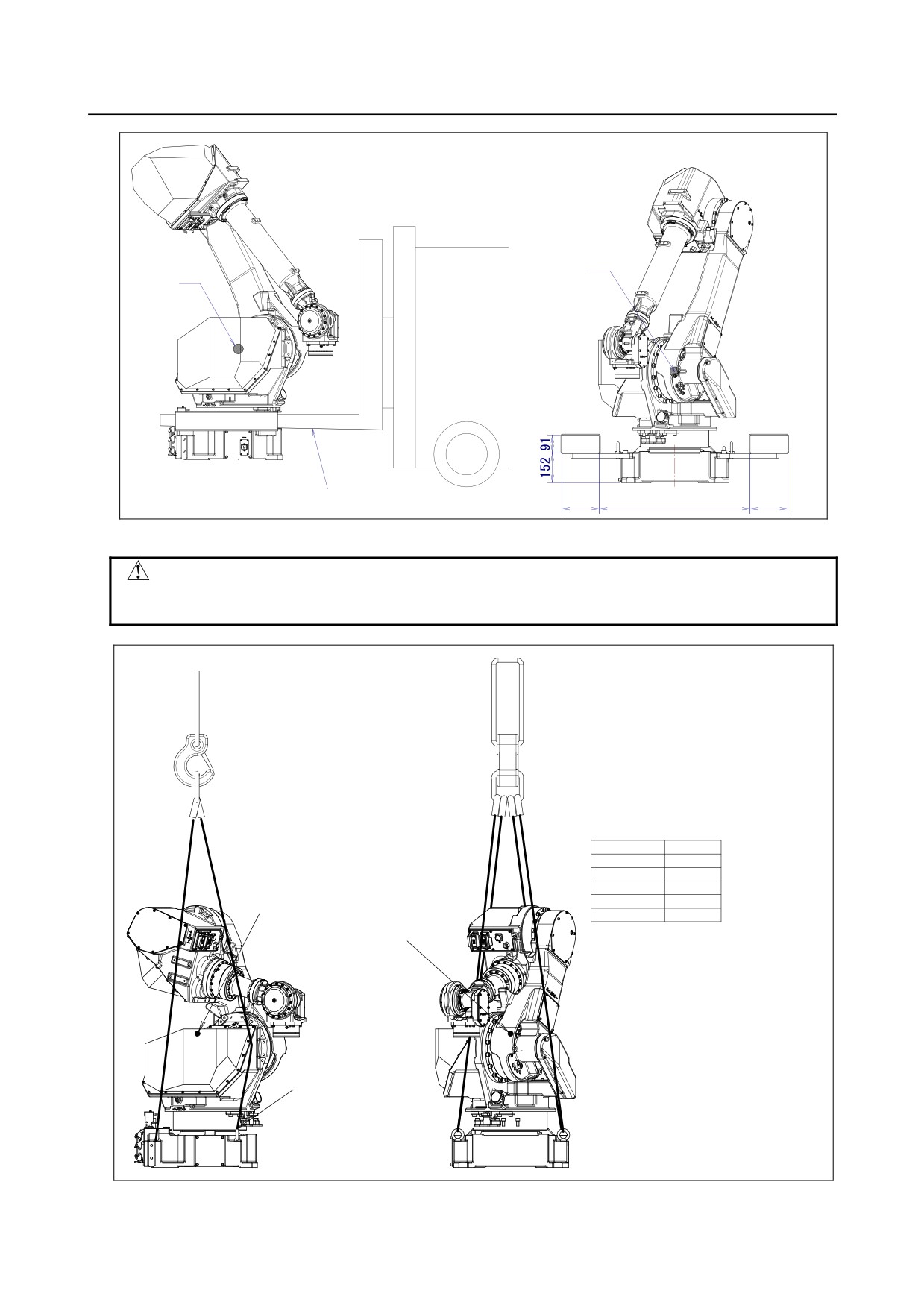
The robot can be transported by a crane or a forklift. When transporting the robot, be sure to change the
posture of the robot to that shown below and lift by using the eyebolts and the transport equipment at
their points.
CAUTION
When hoisting or lowering the robot with a crane or forklift, move it slowly with
great care. When placing the robot on the floor, exercise care to prevent the
installation surface of the robot from striking the floor strongly.
WARNING
1 It is recommended to transport robot detaching the end effector and the
incidental equipment from the robot because there is the following possibilities
when transported with the end effector and the incidental equipment installed.
・ It becomes unstable by the change in the position of the center of the gravity
of the robot while transporting it.
・ The end effector acts by the vibration when transported and an excessive
load acts on far movement and the robot.
2 Please firmly fix the end effector referring to clause 1.1.1 when it is difficult to
detach the end effector and transport it.
3 Use the forklift pockets only to transport the robot with a forklift. Do not use the
forklift pockets for any other transportation method. Do not use the forklift
pockets to secure the robot.
4 Before moving the robot by using forklift pockets, check and tighten any loose
bolts on the forklift pockets.
(1) Transportation using a crane (Fig. 1.1 (b) ,Fig. 1.1 (d) and Fig. 1.1 (f))
Fasten the M16 eyebolts to the four points of the robot base plate and lift the robot by the four
slings.
CAUTION
When lifting the robot, take notice so that the motor, connectors, or cables of the
robot are not damaged by slings.
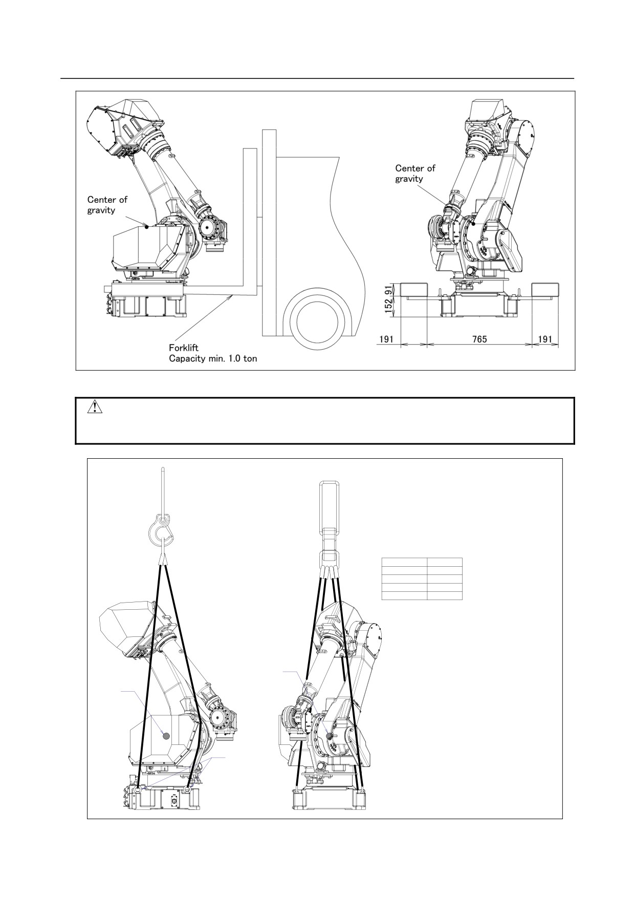
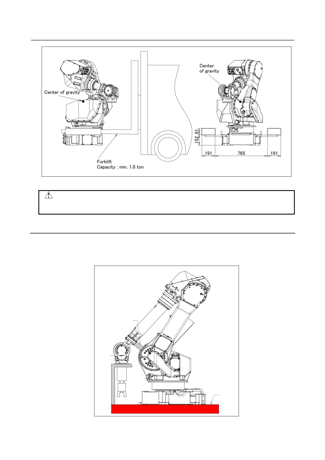
(2) Transportation using a forklift (Fig. 1.1 (c) , Fig. 1.1 (e) and Fig. 1.1 (g))
The specific transport equipment must be attached. Transport equipment is prepared as an option.
- 1 -
1.TRANSPORTATION AND INSTALLATION
B-82274EN/09
Fig. 1.1 (a) Position of the eyebolts and transportation equipment
㪚㫉㪸㫅㪼
㪚㪸㫇㪸㪺㫀㫋㫐㩷㫄㫀㫅㩷㪑㩷㪈㪅㪇㩷㫋㫆㫅
㪥㫆㫋㪼㪀㩷㪈㪅㩷㪤㪸㪺㪿㫀㫅㪼㩷㫎㪼㫀㪾㪿㫋㩷㩷㪌㪍㪇㫂㪾㪅
䇭䇭䇭䇭㪉㪅㩷㪜㫐㪼㪹㫆㫃㫋㩷㪺㫆㫄㫇㫃㫀㪼㪻㩷㫎㫀㫋㪿㩷㪡㪠㪪㩷㪙㩷㪈㪈㪍㪏㪅
䇭䇭䇭䇭㪊㪅㩷㪨㫌㪸㫅㫋㫀㫋㫐㩷㪋㩷㫊㫃㫀㫅㪾㫊
㪪㫃㫀㫅㪾
㪚㪸㫇㪸㪺㫀㫋㫐㩷㫄㫀㫅㩷㪑㩷㪇㪅㪌㩷㫋㫆㫅
Robot posture on transportation
J1-axis
-30°
J2-axis
-30°
J3-axis
-50°
J4-axis
0°
J5-axis
-40°
J6-axis
0°
㪚㪼㫅㫋㪼㫉㩷㫆㪽㩷
㪚㪼㫅㫋㪼㫉㩷㫆㪽㩷
㫋㪿㪼㩷㪾㫉㪸㫍㫀㫋㫐
㫋㪿㪼㩷㪾㫉㪸㫍㫀㫋㫐
㪜㫐㪼㪹㫆㫃㫋㩷㩿䌍㪈㪍䋩
Fig. 1.1 (b) Transportation using a crane (M-710iC/50, /70 ,/50E)
- 2 -
B-82274EN/09
1.TRANSPORTATION AND INSTALLATION
Fig. 1.1 (c) Transportation using a forklift (M-710iC/50, /70, /50E)
CAUTION
Exercise care to prevent the fork of the forklift from striking transport equipments
strongly.
㪚㫉㪸㫅㪼
㪚㪸㫇㪸㪺㫀㫋㫐㩷㫄㫀㫅㩷㪑㩷㪈㪅㪇㩷㫋㫆㫅
㪥㫆㫋㪼㪀㩷㪈㪅㩷㪤㪸㪺㪿㫀㫅㪼㩷㫎㪼㫀㪾㪿㫋㩷㩷㪌㪋㪇㫂㪾㪅
䇭䇭䇭䇭㪉㪅㩷㪜㫐㪼㪹㫆㫃㫋㩷㪺㫆㫄㫇㫃㫀㪼㪻㩷㫎㫀㫋㪿㩷㪡㪠㪪㩷㪙㩷㪈㪈㪍㪏㪅
䇭䇭䇭䇭㪊㪅㩷㪨㫌㪸㫅㫋㫀㫋㫐㩷㪋㩷㫊㫃㫀㫅㪾㫊
㪪㫃㫀㫅㪾
Robot posture on transportation
㪚㪸㫇㪸㪺㫀㫋㫐㩷㫄㫀㫅㩷㪑㩷㪇㪅㪌㩷㫋㫆㫅
J1-axis
-30°
J2-axis
-30°
J3-axis
-48°
J4-axis
-42°
J5-axis
0°
㪚㪼㫅㫋㪼㫉㩷㫆㪽
㪾㫉㪸㫍㫀㫋㫐
㪚㪼㫅㫋㪼㫉㩷㫆㪽
㪾㫉㪸㫍㫀㫋㫐
㪜㫐㪼㪹㫆㫃㫋㩷㩿㪤㪈㪍㪀
Fig. 1.1 (d) Transportation using a crane (M-710iC/50H)
- 3 -
1.TRANSPORTATION AND INSTALLATION
B-82274EN/09
㪚㪼㫅㫋㪼㫉㩷㫆㪽
㪚㪼㫅㫋㪼㫉㩷㫆㪽
㪾㫉㪸㫍㫀㫋㫐
㪾㫉㪸㫍㫀㫋㫐
㪝㫆㫉㫂㫃㫀㪽㫋
㪚㪸㫇㪸㪺㫀㫋㫐㩷㫄㫀㫅㪅㩷㪈㪅㪇㩷㫋㫆㫅
㪈㪐㪈
㪎㪍㪌
㪈㪐㪈
Fig. 1.1 (e) Transportation using a forklift (M-710iC/50H)
CAUTION
Exercise care to prevent the fork of the forklift from striking transport equipments
strongly.
㪚㫉㪸㫅㪼
㪚㪸㫇㪸㪺㫀㫋㫐㩷㫄㫀㫅㩷㪑㩷㪈㪅㪇㩷㫋㫆㫅
㪪㫃㫀㫅㪾
㪥㫆㫋㪼㪀㩷㪈㪅㩷㪤㪸㪺㪿㫀㫅㪼㩷㫎㪼㫀㪾㪿㫋㩷㩷㪌㪋㪌㫂㪾㪅
㪚㪸㫇㪸㪺㫀㫋㫐㩷㫄㫀㫅㩷㪑㩷㪇㪅㪌㩷㫋㫆㫅
䇭䇭䇭䇭㪉㪅㩷㪜㫐㪼㪹㫆㫃㫋㩷㪺㫆㫄㫇㫃㫀㪼㪻㩷㫎㫀㫋㪿㩷㪡㪠㪪㩷㪙㩷㪈㪈㪍㪏㪅
䇭䇭䇭䇭㪊㪅㩷㪨㫌㪸㫅㫋㫀㫋㫐㩷㪋㩷㫊㫃㫀㫅㪾㫊
Robot posture on transportation
J1-axis
-30°
J2-axis
-25°
J3-axis
-15°
J4-axis
0°
J5-axis
-75°
㪚㪼㫅㫋㪼㫉㩷㫆㪽
㪚㪼㫅㫋㪼㫉㩷㫆㪽
J6-axis
0°
㫋㪿㪼㩷㪾㫉㪸㫍㫀㫋㫐
㫋㪿㪼㩷㪾㫉㪸㫍㫀㫋㫐
㪜㫐㪼㪹㫆㫃㫋㩷㩿䌍㪈㪍䋩
Fig. 1.1 (f) Transportation using a crane (M-710iC/50S)
- 4 -
B-82274EN/09
1.TRANSPORTATION AND INSTALLATION
Fig. 1.1 (g) Transportation using a forklift (M-710iC/50S)
CAUTION
Exercise care to prevent the fork of the forklift from striking transport equipments
strongly.
1.1.1
Transportation with an End Effector Attached
When transporting a robot with an end effector such as a welding gun or hand attached, secure the arm
with wood. If the arm is not secured, the end effector may oscillate for a cause such as vibration during
transportation, thus imposing a large impact load on the reducer of the robot and damaging the reducer at
an earlier stage.
㪮㫆㫆㪻㫊
㪝㫀㫏㫀㫅㪾
㪧㪸㫃㫃㪼㫋
Fig. 1.1.1 Example of securing the arm during transportation when an end effector is attached
- 5 -
1.TRANSPORTATION AND INSTALLATION
B-82274EN/09
1.2
INSTALLATION
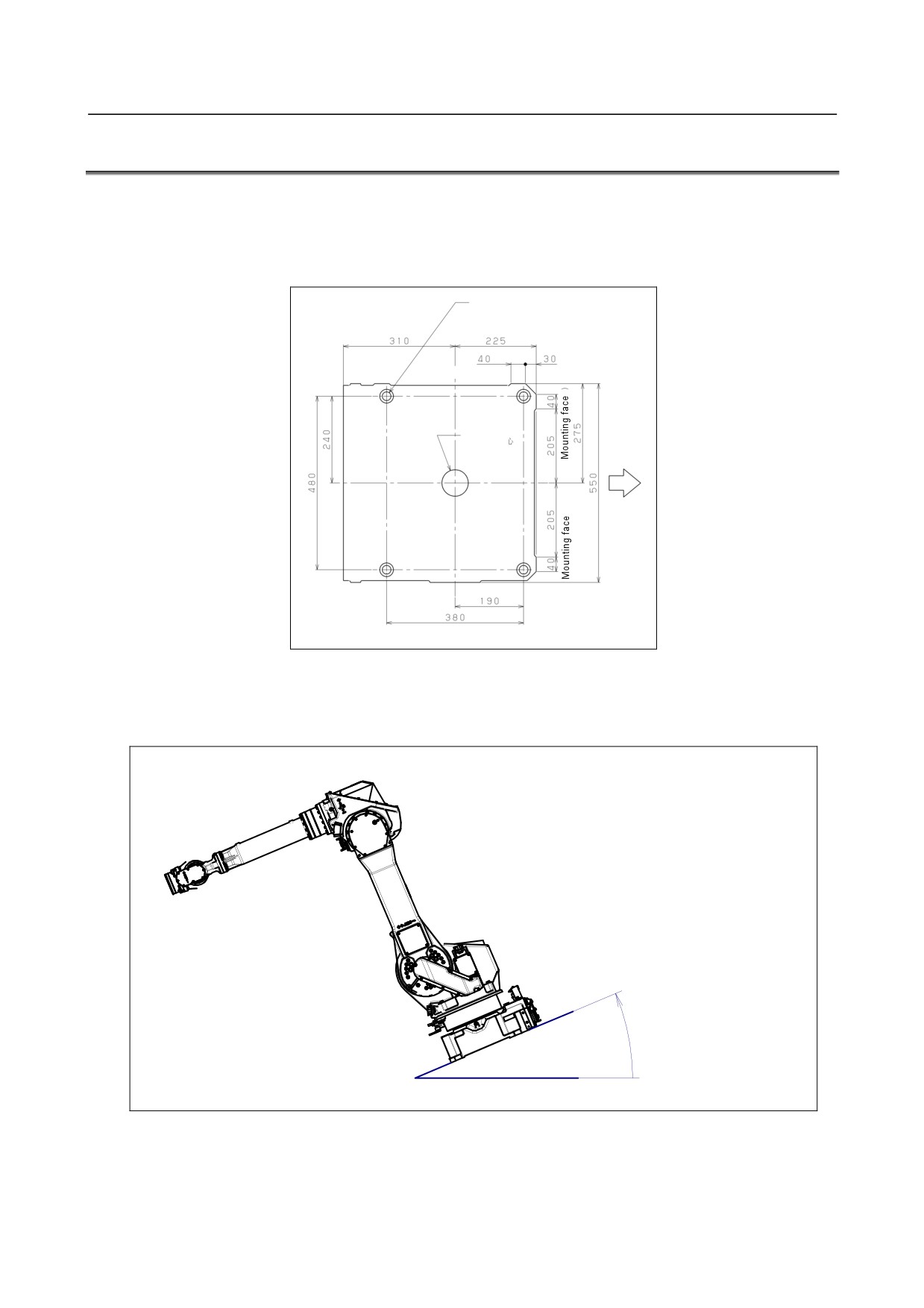
Fig. 1.2 (a) shows the robot base dimensions. Avoid placing any object in front of the robot on the
mounting face to facilitate the installation of the mastering fixture.
Following shows the actual example of robot installation.
For fixing robot
4-Φ24 through
Φ38 facing depth 5
Mounting face
Rotation
center
Front
of J1 axis
Fig. 1.2 (a) Dimensions of the robot base
Fig.1.2 (b) shows definition of mounting angle. Input angle of mounting surface when you install robot
referring to Fig.1.2 (b).
㪂
㪘㫅㪾㫃㪼㩷㫆㪽
㫄㫆㫌㫅㫋㫀㫅㪾㩷㫊㫌㫉㪽㪸㪺㪼
Fig.1.2 (b) Mounting angle
- 6 -
B-82274EN/09
1.TRANSPORTATION AND INSTALLATION
1.2.1
Actual Installation Example
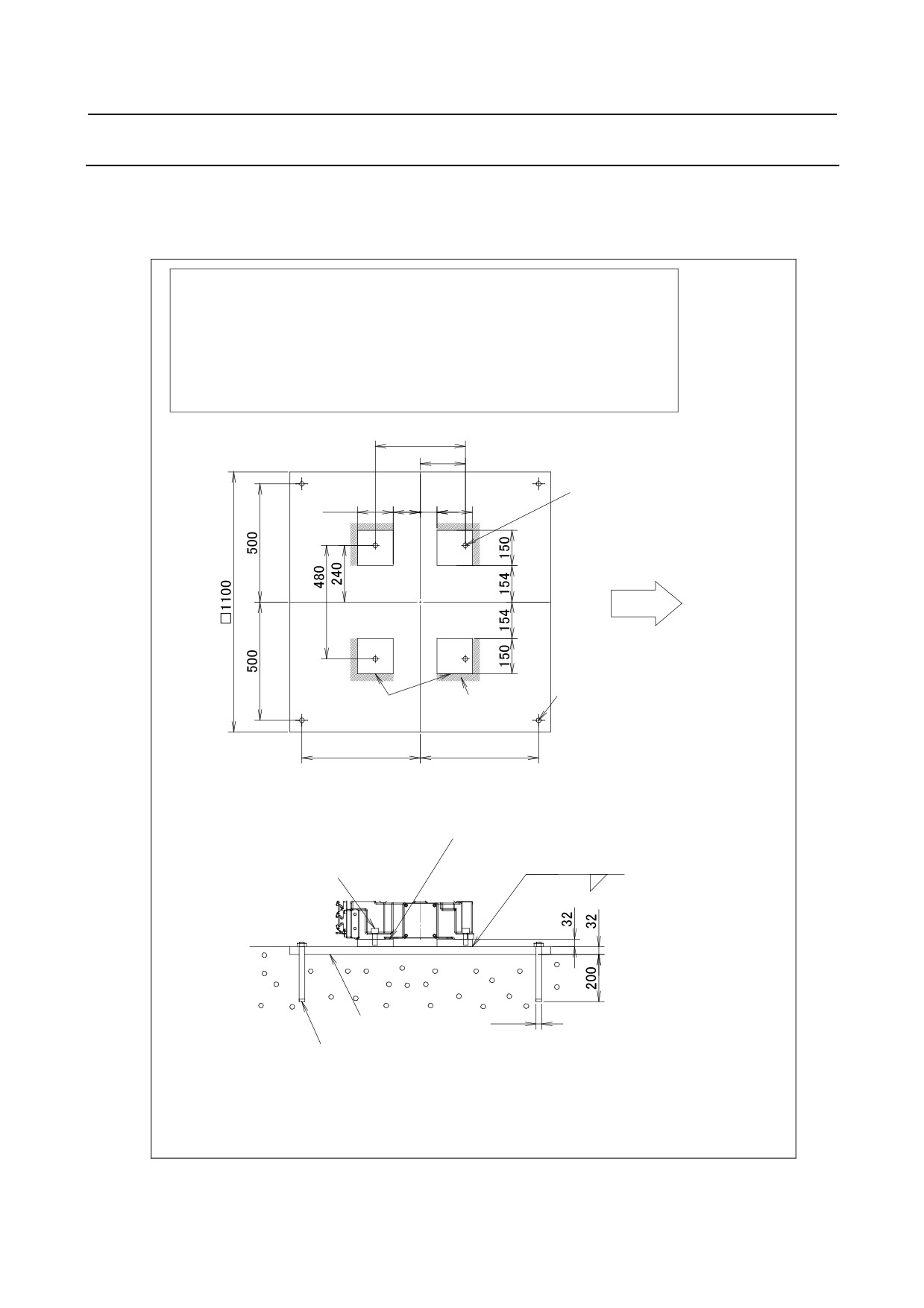
Fig. 1.2.1 (a) shows the actual example of the robot installation.
The floor plate is imbedded in concrete and fastened with four M20 (strength classification 4.8) chemical
anchors. Also, fasten the base plate to the robot base using four M20×50 bolts (strength classification
12.9). Next, position the robot, and weld the base plate to the floor plate. (Floor length is 10 to 15mm.)
㪧㪸㫉㫋㫊㩷㫋㫆㩷㪹㪼㩷㫇㫉㪼㫇㪸㫉㪼㪻㩷㪹㫐㩷㪺㫌㫊㫋㫆㫄㪼㫉㪅
㪩㫆㪹㫆㫋㩷㫄㫆㫌㫅㫋㫀㫅㪾㩷㪹㫆㫃㫋㩷㩷㩷㪤㪉㪇㪯㪌㪇㩷㩷㩷㩿㪪㫋㫉㪼㫅㪾㫋㪿㩷㪺㫃㪸㫊㫊㫀㪽㫀㪺㪸㫋㫀㫆㫅㩷㪈㪉㪅㪐㪀㩷㩷㩷㪋㩷㫇㪺㫊㪅
㪚㪿㪼㫄㫀㪺㪸㫃㩷㪸㫅㪺㪿㫆㫉㩷㩷㩷㩷㩷㩷㩷㩷㪤㪉㪇 㩿㪪㫋㫉㪼㫅㪾㫋㪿㩷㪺㫃㪸㫊㫊㫀㪽㫀㪺㪸㫋㫀㫆㫅㩷㪋㪅㪏㪀㩷㩷㩷㩷㩷㩷㩷㩷㩷㩷㩷㩷㪋㩷㫇㪺㫊㪅
㪙㪸㫊㪼㩷㫇㫃㪸㫋㪼㩷㩷㩷㩷㩷㩷㩷㩷㩷㩷㩷㩷㩷㩷㩷㩷㪫㪿㫀㪺㫂㫅㪼㫊㫊㩷㪊㪉㫋
㪋㩷㫇㪺㫊㪅
㪝㫃㫆㫆㫉㩷㫇㫃㪸㫋㪼㩷㩷㩷㩷㩷㩷㩷㩷㩷㩷㩷㩷㩷㩷㩷㩷㪫㪿㫀㪺㫂㫅㪼㫊㫊㩷㪊㪉㫋㩷㩷㩷㩷㩷㩷㩷㩷㩷㩷㩷㩷㩷㩷㩷㩷㩷㩷㩷㩷㩷㩷㩷㩷㩷㩷㩷㩷㩷㩷㩷㩷㩷㩷㩷㩷㩷㪈㩷㫇㪺㫊㪅
㪊㪏㪇
㪈㪐㪇
㪋㪄㪤㪉㪇
㪈㪌㪇
㪈㪈㪌
㪎㪇 㪈㪌㪇
㪩㫆㪹㫆㫋㩷㪽㫉㫆㫅㫋
㪮㪼㫃㪻㫀㫅㪾㩷
㪋㪄O㪉㪋
㪙㪸㫊㪼㩷㫇㫃㪸㫋㪼
㫇㪸㫉㫋
㪝㫃㫆㫆㫉㩷㫇㫃㪸㫋㪼
㪌㪇㪇
㪌㪇㪇
㪩㫆㪹㫆㫋㩷㫄㫆㫌㫅㫋㫀㫅㪾㩷㪹㫆㫃㫋
㪤㪉㪇㪯㪌㪇㩿㪋㫇㪺㫊㪀
㪙㪸㫊㪼㩷㫇㫃㪸㫋㪼
㪪㫋㫉㪼㫅㪾㫋㪿㩷㪺㫃㪸㫊㫊㫀㪽㫀㪺㪸㫋㫀㫆㫅㩷㩷㪈㪉㪅㪐
㪮㪼㫃㪻㫀㫅㪾㩷㪸㪽㫋㪼㫉㩷㫇㫆㫊㫀㫋㫀㫆㫅㫀㫅㪾
㪫㫀㪾㪿㫋㪼㫅㫀㫅㪾㩷㫋㫆㫉㫈㫌㪼㩷㪌㪉㪐㪅㪉㪥㫄㩿㪌㪋㫂㪾㪽㫄㪀
㪈㪇䌾㪈㪌
㪝㫃㫆㫆㫉㩷㫇㫃㪸㫋㪼
O㪉㪋
㪚㪿㪼㫄㫀㪺㪸㫃㩷㪸㫅㪺㪿㫆㫉㩷㪤㪉㪇䋨㪋㫇㪺㫊䋩
㪪㫋㫉㪼㫅㪾㫋㪿㩷㪺㫃㪸㫊㫊㫀㪽㫀㪺㪸㫋㫀㫆㫅㩷㪋㪅㪏
㪫㫀㪾㪿㫋㪼㫅㫀㫅㪾㩷㫋㫆㫉㫈㫌㪼㩷㪈㪏㪍㪅㪉㪥㫄㩿㪈㪐㪅㪈㫂㪾㪽㫄㪀
㩿㪥㫆㫋㪼㩷㪈㪀 㪠㫅㫊㫋㪸㫃㫃㪸㫋㫀㫆㫅㩷㫎㫆㫉㫂㩷㩿㫎㪼㫃㪻㫀㫅㪾㪃㩷㪸㫅㪺㪿㫆㫉㫀㫅㪾㪅㪼㫋㪺㪀㩷㪸㫉㪼㩷㫇㫉㪼㫇㪸㫉㪼㪻㩷㪹㫐㩷㪺㫌㫊㫋㫆㫄㪼㫉㪅
㩿㪥㫆㫋㪼㩷㪉㪀㩷㩷㪙㫌㫉㫉㫐㩷㫋㪿㪼㩷㪽㫃㫆㫆㫉㩷㫇㫃㪸㫋㪼㩷㫀㫅㩷㪺㫆㫅㪺㫉㪼㫋㪼㪅
Fig. 1.2.1 (a) Actual installation example
- 7 -
1.TRANSPORTATION AND INSTALLATION
B-82274EN/09
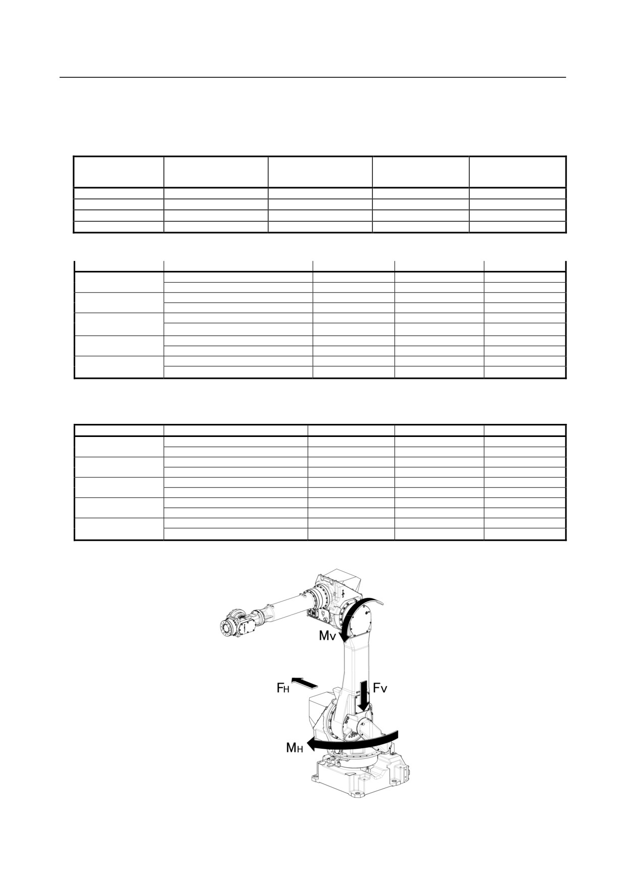
Fig. 1.2.1 (b), Table 1.2.1 (a) to Table 1.2.1 (c) indicate the force and moment applied to the base plate at
the time of Power off stop of the robot and indicate the stopping distance and time of the J1 through J3
axes until the robot stopping by Power-Off stop or by Controlled stop after input of the stop signal.
Refer to the data when considering the strength of the installation face.
Table1.2.1 (a) Force and moment during Power-Off stop
Force in horizontal
Vertical moment
Force in vertical direction
Horizontal moment
Model
direction
MV [kNm (kgfm)]
FV [kN (kgf)]
MH [kNm (kgfm)]
FH [kN (kgf)]
M-710iC/50, /50E
17.6 (1800)
14.7 (1500)
5.9 (600)
8.0 (820)
M-710iC/70
18.6 (1900)
16.0 (1630)
5.9 (600)
8.0 (820)
M-710iC/50H
17.6 (1800)
14.7 (1500)
5.9 (600)
8.0 (820)
M-710iC/50S
13.2 (1350)
14.7 (1500)
5.9 (600)
7.4 (750)
Table 1.2.1 (b) Stopping time and distance until the robot stopping by Power-Off stop after input of stop signal
Model
J1-axis
J2-axis
J3-axis
Stopping time [msec]
310
281
212
M-710iC/50
Stopping distance [deg] (rad)
27.1
(0.47)
24.6
(0.43)
18.6
(0.32)
Stopping time [msec]
294
286
238
M-710iC/50E
Stopping distance [deg] (rad)
26.9(0.47)
23.3(0.41)
23.3(0.41)
Stopping time [msec]
311
205
160
M-710iC/70
Stopping distance [deg] (rad)
24.9
(0.43)
12.3
(0.21)
9.6
(0.17)
Stopping time [msec]
284
252
220
M-710iC/50H
Stopping distance [deg] (rad)
28.9(0.50)
22.9(0.40)
21.5(0.38)
Stopping time [msec]
166
155
151
M-710iC/50S
Stopping distance [deg] (rad)
14.5
(0.25)
13.6
(0.24)
13.2
(0.23)
* override : 100%
* Max. payload, and max. inertia posture
Table1.2.1 (c) Stopping time and distance until the robot stopping by Controlled stop after input of stop signal
Model
J1-axis
J2-axis
J3-axis
Stopping time [msec]
636
644
628
M-710iC/50
Stopping distance [deg] (rad)
60.5
(1.06)
62.5
(1.09)
60.4
(1.05)
Stopping time [msec]
638
654
630
M-710iC/50E
Stopping distance [deg] (rad)
60.7(1.06)
61.1(1.07)
60.5(1.06)
Stopping time [msec]
756
764
708
M-710iC/70
Stopping distance [deg] (rad)
63.9
(1.11)
47.5
(0.83)
46.3
(0.81)
Stopping time [msec]
652
644
636
M-710iC/50H
Stopping distance [deg] (rad)
61.2(1.07)
61.2(1.07)
61.6(1.07)
Stopping time [msec]
492
492
492
M-710iC/50S
Stopping distance [deg] (rad)
49.0
(0.85)
47.8
(0.83)
47.8
(0.83)
* override : 100%
* Max. payload, and max. inertia posture
*
Fig. 1.2.1 (b) Force during Power-Off Stop
- 8 -
///////////////////////////////////////