FANUC Series 0i-MODEL F Plus. CONNECTION MANUAL (FUNCTION) - page 361
 

  Index      Manuals     FANUC Series 0i-MODEL F Plus. CONNECTION MANUAL (FUNCTION) B-64693EN-1/01


Search            copyright infringement  


Content      ..     359      360      361      362     ..


FANUC Series 0i-MODEL F Plus. CONNECTION MANUAL (FUNCTION) - page 361


19. MAINTENANCE FUNCTION


B-64693EN-1/01


- 2842 - 


Detect trouble 

Waveform data output 

failure signal 

WVTF<F0578.1> 

Finish output 

Time 

Waveform data 

transfer signal 

WVTRNS 

<F0578.0> 

SV or SP alarm 

Waveform data 

re-output signal 

WVROP<G0589.2> 

(remained 0) 

(remained 0) 

NOTE: SV or SP alarms does not release even if Waveform data transfer signal changes into “1”. 


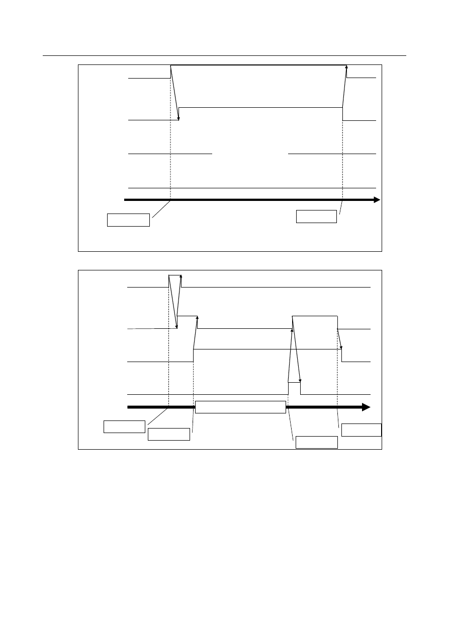
Fig. 19.2.6 (b) Sequence of normal output (when the trouble is detected by SV or SP alarm) 


Detect trouble 

Waveform data 

output failure signal 

WVTF<F0578.1> 

Output failure 

Finish output 

Time 

Waveform data 

transfer signal 

WVTRNS 

<F0578.0> 

Trouble diagnosis 

data latching signal 

TDDL<G0589.1> 

Waveform data 

re-output signal 

WVROP<G0589.2> 

Start re-output 

Resolve the cause of failure


Fig. 19.2.6 (c) Sequence when output fails (when the trouble is detected by the signal) 


B-64693EN-1/01


19. MAINTENANCE FUNCTION


- 2843 - 


Detect trouble 

Waveform data 

output failure signal 

WVTF<F0578.1> 

Output failure 

Finish output 

Time 

Waveform data 

transfer signal 

WVTRNS 

<F0578.0> 

SV or SP alarm 

Waveform data 

re-output signal 

WVROP<G0589.2> 

Start re-output 

(Resolve the cause of failure) 

NOTE: SV or SP alarms does not release even if Waveform data transfer signal changes into “1”. 


Fig. 19.2.6 (d) Sequence when output fails (when the trouble is detected by SV or SP alarm) 


NOTE 

1  Make all paths in alarm states by external alarms before the output starts if 

trouble is detected by Trouble diagnosis data latching signal (TDDL). 

2  Remain alarm states during the output. 
3  Output of waveform data cannot be stopped by reset operations. 
4  It is impossible to output other data by screen operations during the data output. 

Warning message “THE MACHINE IS UNDER USE” is displayed if an output 
operation is made during the data output. 

5  Screen hard copy cannot be used during the output. BG alarm “HARD COPY 

REJECTED DURING OUTPUT” occurs if screen hard copy is requested by a 
MDI operation or a signal. In the same way, EW_REJECT is returned if screen 
hard copy is requested from a FOCAS2 function. 

6  Operations listed below are accepted after the output finishes if they are 

operated during the data output: 
-  Changing the active path (only for display) 
-  Saving alarm history (Time when the save is done is saved as the occurrence 

time of the alarm.) 

-  Writing PMC data on FROM 
-  Setting Memory protection signal KEYP<G0046.0> 
-  Changing displayed language 

7  It takes several 10 seconds or a few minutes to output whole data. 
8  Re-output makes a new file involving whole data. The old defective file is 

overwritten by the new file. 

9  Reserve enough area on Data Server to output waveform data by transferring 

files in “SVSPWAVE” folder to host computers etc. regularly because waveform 
data is always output automatically if trouble is detected. 
Diagnosis No.4600 will help the data transfer. 

10 Specify ratio of capacity available for data folder and number of registered files 

among total capacity and the maximum number of registered files of CF card 
mounted on data server in parameter No.24315. 

19. MAINTENANCE FUNCTION


B-64693EN-1/01


- 2844 - 

19.2.7 

Output File Format 

Waveform data is output in CSV format. 
 

Filename 

Output filenames are in the format “SVSPW_yyyymmddHHMMSS.CSV”. 
The part of “yyyymmddHHMMSS” means date when trouble occurs. 

yyyy:  year 

(2000-2999) 

mm:   month  (01-12) 

dd:    day 

(01-31) 

HH:   hour 

(00-23) 

MM:  minute  (00-59) 

SS:    second  (00-59) 


File format 

File format is as shown below. 


%
-------------------------------------------------------------
                         Wave Data of Trouble Diagnosis

←Title

-------------------------------------------------------------
Trouble Occurs: November 11 2011 at 14:00:00 [ = 30000ms in data]

←Time when trouble occurs

Trigger           : Signal (G589.1) ON

←How to detect trouble

-------------------------------------------------------------


SV1

SV1 …

SV2

SV2 …

←Axis number

TIME COM. PULSE F.B. PULSE … COM. PULSE F.B. PULSE …

←Data name

[ms]

[pulse]

[pulse] …

[pulse]

[pulse] …

←Data unit

0

50

50 …

50

50 …

←Data

4

50

50 …

50

50 …

8

50

50 …

50

50 …

12

50

50 …

50

50 …

… …

… …

%


B-64693EN-1/01


19. MAINTENANCE FUNCTION


- 2845 - 

19.2.8 

Restriction 

Sampling of this function stops when sampling of Waveform diagnosis function is active. 
Note that Servos and spindles waveform data is not output if something trouble occurs during sampling of 
Waveform diagnosis function is active. 
 

Signal 

Trouble diagnosis data monitoring signal TDDM<Gn589.0> 

    [Classification]  Input signal 
 

  [Function]  Clears latched data of Trouble diagnosis function and changes the state from 

“LATCHED”  to  “SAMPLING”.  In addition, sampling of all paths starts in Servo / 
spindle waveform data output function. 


  [Operation]  When this signal is set from “0”  to  “1”,  latched data of Trouble diagnosis function is 

cleared and the state changes from “LATCHED” to “SAMPLING”. In addition, sampling 
of waveform data starts. Note that this signal is ignored when Wave data transfer signal 
WVTRNS is “1”. Since this signal is also ignored when SV or SP alarm occurs, set this 
signal after resolving the causes of alarms. 


NOTE 


Only the signal of 1

st

 path is effective when Servo / spindle 

waveform data output function is effective. 


Trouble diagnosis data latching signal TDDL<Gn589.1> 

    [Classification]  Input signal 
 

  [Function]  Latches data of Trouble diagnosis function and changes the state from “SAMPLING” to 

“LATCHED”. In addition, sequence of outputting waveform data starts in Servo / spindle 
waveform data output function. 


  [Operation]  When this signal is set from “0” to “1”, data of Trouble diagnosis function is latched and 

the state changes from “SAMPLING”  to  “LATCHED”. In addition, sequence of 
outputting waveform data starts. Note that this signal is ignored when the state of Trouble 
diagnosis function is “LATCHED”. 


NOTE 


Only the signal of 1

st

 path is effective when Servo / spindle 

waveform data output function is effective. 


Waveform data re-output signal WVROP<G0589.2> 

    [Classification]  Input signal 
 

  [Function]  Starts re-output of waveform data if output of servos and spindles waveform data fails 

because of shortage of memory and so on. 


  [Operation]  When this signal is set from “0”  to  “1”,  re-output of waveform data is started. Start 

re-output by this signal after resolving causes of output failure. Note that this signal is 
ignored when Waveform data transfer failure signal WVTF is “0”. 


Signal address 


#7 

#6 

#5 

#4 

#3 

#2 

#1 

#0 

Gn589 


WVROP 

TDDL 

TDDM 


19. MAINTENANCE FUNCTION


B-64693EN-1/01


- 2846 - 

Waveform data transfer signal WVTRNS<F0578.0> 

    [Classification]  Output signal 
 

  [Function]  Notifies that trouble was detected and that output of waveform data does not finish in 

Servo / spindle waveform data output function. Note that this signal is “1” even if output 
of waveform data does not run during sampling after the trouble. 


  [Operation]  This signal is “1” when output of waveform data does not finish. 


  This signal is “0” when output of waveform data finishes. 


Waveform data transfer failure signal WVTF<F0578.1> 

    [Classification]  Output signal 
 

  [Function]  Notifies that output of waveform data failed in Servo / spindle waveform data output 

function. Re-output of the data can be started by Waveform data re-output signal when 
this signal is “1”. 


  [Operation]  This signal is “1” when output of waveform data failed. 


  This signal is “0” in the following cases: 

1.


Output of waveform data was normal. 

2.


Sampling of waveform data was restarted. 

3.


Power was turned off and on. 


Signal address 


#7 

#6 

#5 

#4 

#3 

#2 

#1 

#0 

Fn578 


WVTF 

WVTRNS 


Parameter 

24315 


Ratio of use of data folder of data server   


[Input type]  Parameter input 


[Data type]  Byte system 

[Valid data range]  0 to 9(common to the system) 

Specify ratio of capacity available for data folder and number of registered files among 
total capacity and the maximum number of registered files of CF card mounted on data 
server. 
For example, when formatting is executed by setting parameter DFR to 3, while using a 
CF card with 2 GB capacity, in data folder it is possible to use up to about 0.6 GB, which 
is 30% of the total capacity, and available capacity of NC program storage area is 
approximately 1.4 GB. 
Also, if 2047 files can be registered, the maximum number of registered files is 614 in the 
data folder and 1433 in NC program. If 0 is specified, the data folder cannot be available 
and the data folder is not created even when formatting.   
When 10 or more or -1 or less is specified, it assumed to be 5. 


#7 

#6 

#5 

#4 

#3 

#2 

#1 

#0 

24318 


SPT 

WDT 


[Input type]  Parameter input 


[Data type]  Bit 


NOTE 


When this parameter is set, the power must be turned off before 
operation is continued. 


#0  WDT

  Servo / spindle waveform data output function is 

0: 

Effective. 

1: 

Not effective. 


B-64693EN-1/01


19. MAINTENANCE FUNCTION


- 2847 - 

#1  SPT 

In Trouble diagnosis function and Servo / spindle waveform data output function, Trouble 

diagnosis data monitoring signal and Trouble diagnosis data latching signal are 

0: 

Ignored. 

1: 

Not ignored. 


24319 


Sampling time of waveform data before trouble 


[Input type]  Parameter input 


[Data type]  Byte 


[Unit of data]  sec 


[Valid data range]  0 to 40 


24320 


Sampling time of waveform data after trouble 


[Input type]  Parameter input 


[Data type]  Byte 


[Unit of data]  sec 


[Valid data range]  0 to 40 

Set sampling times before and after trouble in Servo / spindle waveform data  output 
function. 
Specify the sampling times so that the sum of them is within 40 seconds because room for 
the buffer is limited. Note that data is not sampled as specified by these parameters if the 
sum exceeds 40 seconds. 
The following is an example when the sum exceeds 40 seconds: 
When 30 seconds is specified for the sampling time before trouble and 20 seconds is 
specified for the sampling time after trouble, waveform data of 30 seconds before trouble 
and of 10 seconds after trouble is obtained. 
When 50 seconds is specified for the sampling time before trouble and 10 seconds is 
specified for the sampling time after trouble, waveform data of only 40 seconds before 
trouble is obtained. 


#7 

#6 

#5 

#4 

#3 

#2 

#1 

#0 

24321 


MCR 

HTS 

TCM 

ASD 

REF 

PER 

FBP 

CMP 


[Input type]  Parameter input 


[Data type]  Bit axis 


#0  CMP

  In Servo / spindle waveform data output function, accumulated command pulse of a servo 

axis is 
0: 

Output. 

1: 

Not output. 


#1  FBP

  In Servo / spindle waveform data output function, accumulated feedback pulse of a servo 

axis is 
0: 

Output. 

1: 

Not output. 


#2  PER

  In Servo / spindle waveform data output function, position error of a servo axis is 

0: 

Output. 

1: 

Not output. 


#3  REF

  In Servo / spindle waveform data output function, reference counter of a servo axis is 

0: 

Output. 

1: 

Not output. 


#4  ASD

  In Servo / spindle waveform data output function, actual speed of a servo axis is 

19. MAINTENANCE FUNCTION


B-64693EN-1/01


- 2848 - 

0: 

Output. 

1: 

Not output. 


#5  TCM

  In Servo / spindle waveform data output function, torque command of a servo axis is 

0: 

Output. 

1: 

Not output. 


#6  HTS

  In Servo / spindle waveform data output function, heat simulation of a servo axis is 

0: 

Output. 

1: 

Not output. 


#7  MCR

  In Servo / spindle waveform data output function, motor current of a servo axis is 

0: 

Output. 

1: 

Not output. 


#7 

#6 

#5 

#4 

#3 

#2 

#1 

#0 

24322 


AR2 

AMR 

EFC 

AR1 

DLV 


[Input type]  Parameter input 


[Data type]  Bit axis 


#0  DLV

  In Servo / spindle waveform data output function, disturbance level of a servo axis is 

0: 

Output. 

1: 

Not output. 


#1  AR1

  In Servo / spindle waveform data output function, arbitrary data 1 of a servo axis is 

0: 

Output. 

1: 

Not output. 


#2  EFC

  In Servo / spindle waveform data output function, effective current of a servo axis is 

0: 

Output. 

1: 

Not output. 


#3  AMR

  In Servo / spindle waveform data output function, AMR data of a servo axis is 

0: 

Output. 

1: 

Not output. 


#4  AR2

  In Servo / spindle waveform data output function, arbitrary data 2 of a servo axis is 

0: 

Output. 

1: 

Not output. 


#7 

#6 

#5 

#4 

#3 

#2 

#1 

#0 

24323 


MCR 

TCM 

PER 

LDM 

SPD 


[Input type]  Parameter input 


[Data type]  Bit spindle 


#0  SPD

  In Servo / spindle waveform data output function, actual motor speed of a spindle axis is 

0: 

Output. 

1: 

Not output. 


#1  LDM

  In Servo / spindle waveform data output function, load meter of a spindle axis is 

0: 

Output. 

1: 

Not output. 


#2  PER

  In Servo / spindle waveform data output function, position error of a spindle axis is 

B-64693EN-1/01


19. MAINTENANCE FUNCTION


- 2849 - 

0: 

Output. 

1: 

Not output. 


#3  TCM

  In Servo / spindle waveform data output function, torque command of a spindle axis is 

0: 

Output. 

1: 

Not output. 


#4  MCR

  In Servo / spindle waveform data output function, motor current of a spindle axis is 

0: 

Output. 

1: 

Not output. 


Diagnosis 

Diagnosis 

4600 


Counter of output of waveform data 


[Data type]  Byte 


[Unit of data]  1 time 

[Valid data range]  0-255 

The state of output of servos and spindles waveform data can be displayed. 
 
Power-on clears this value to 0 and then 1 is added when output starts. In addition, 1 is 
added again when output finishes normally. Therefore, odd number means that output is 
active and even number means that output is not active. 
 
Note that this value changes as follows if output fails: 

1 is added when output starts. 

1 is subtracted when output fails. 

1 is added when output starts again. 

1 is added when output finishes normally. 


NOTE 

1  This value is not cleared even if power is turned off. 
2  This value is counted up from 0 again if this value exceeds 255. 


Content      ..     359      360      361      362     ..