FANUC Series 0i-MODEL F Plus. CONNECTION MANUAL (FUNCTION) - page 343
 

  Index      Manuals     FANUC Series 0i-MODEL F Plus. CONNECTION MANUAL (FUNCTION) B-64693EN-1/01


Search            copyright infringement  


Content      ..     341      342      343      344     ..


FANUC Series 0i-MODEL F Plus. CONNECTION MANUAL (FUNCTION) - page 343


17. EMBEDDED ETHERNET FUNCTION


B-64693EN-1/01


- 2698 - 

COMMON screen (DETAIL) 

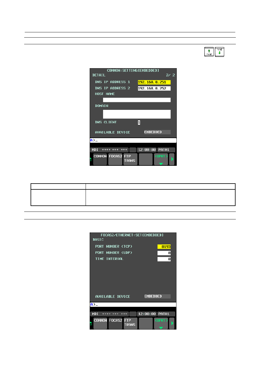
When using the DNS  client  function, press soft key  [COMMON] then press page key 


. The 

COMMON screen (DETAIL) (Fig. 17.2.6.2(b)) is displayed. Set the DNS IP address setting items. 


Fig. 17.2.6.2 (b) COMMON screen (DETAIL) 


Display items 

Item 

Description 

DNS IP ADDRESS 1, 2 

Up to two DNS IP addresses can be specified. 
The CNC searches for the DNS server using DNS IP addresses 1 and 2 in that 
order.   


FOCAS2 screen 

Press soft key [FOCAS2]. The FOCAS2 screen (Fig. 17.2.6.2(c)) is displayed. 


Fig. 17.2.6.2 (c) FOCAS2 screen 


B-64693EN-1/01


17. EMBEDDED ETHERNET FUNCTION


- 2699 - 

Setting items 

Item 

Description 

PORT NUMBER (TCP) 

Specify a port number to be used with the unsolicited messaging function 
(FOCAS2/Ethernet function). The valid input range is 5001 to 65535. 

PORT NUMBER (UDP) 

Set this item to 0. 

TIME INTERVAL 

Set this item to 0. 


17.2.6.3 

Mode selection 

This subsection describes the selection of a mode for setting the unsolicited messaging function. 
 

Unsolicited Message screen (BASIC) 

Press soft key [UNSOLI MSG]. The Unsolicited Message screen (BASIC) (Fig. 17.2.6.3(a)) is displayed. 


Fig. 17.2.6.3 (a) Unsolicited Message screen 1 (BASIC) 

Setting items 

Item 

Description 

MODE 

Select a mode for setting the unsolicited messaging function. 
For the method of selection, see "

Operation

" described later. 

When "CNC MODE" is selected 


This mode enables setting on the CNC screen. 


In this case, setting on the personal computer is disabled. 


For details, see Subsection 18.2.4.4, "Setting on the CNC screen". 

When "PC MODE" is selected 


This mode enables setting on the personal computer. 


In this case, setting on the CNC screen is disabled. 


For details, see Subsection 18.2.4.5, "Setting on the personal computer". 


NOTE 

1  The mode is set to "PC MODE" at the time of initial use. 
2  The mode can be switched only in the "Not Ready" state. For the "Not Ready" 

state, see "

Display items

" provided later.   

3  If the mode is switched from "CNC MODE" to "PC MODE", all parameters set on 

the CNC screen are cleared. 

4  The mode can be switched on the available device side only. 

17. EMBEDDED ETHERNET FUNCTION


B-64693EN-1/01


- 2700 - 

Operation 

The mode can be switched as described below. 
 

Press soft key [(OPRT)]. Soft key [MODE] is displayed. (Fig. 17.2.6.3(b)) 


Fig. 17.2.6.3 (b)   


Press soft key [MODE]. Soft keys [CNC MODE] and [PC MODE] are displayed. (Fig. 17.2.6.3(c)) 


Fig. 17.2.6.3 (c)   


Display items 

Item 

Description 

IP ADDRESS 

Displays the IP address of the personal computer currently connected. 
(Example of display format: "192.168.0.1") 

STATUS 

Displays the current state. 
The following five states are available: 
<1> Not Ready 
 

State where data is not transmitted even when a request for data transmission is 
made from an NC program or ladder program 

<2> Ready 
 

State where data is transmitted when a request for data transmission is made from 
an NC program or ladder program 

<3> Sending... 
 

State present from the acceptance of a request for data transmission from an NC 
program or ladder program until data transmission is completed 

<4> Receiving... 
 

State present from completion of data transmission until response data is received 

<5> Completed 
 

State present from reception of response data until response data processing is 
completed 

 
[Supplement] 

Data transmission 


Means unsolicited message transmission (CNC

PC). 

Response data 


Means a response to an unsolicited message (PC

CNC). 

AVAILABLE DEVICE 

Device where embedded Ethernet is currently enabled. 
The embedded Ethernet port or PCMCIA Ethernet card is displayed. 


NOTE 

1  To switch the state from "Not Ready" to "Ready”, the FOCAS2 function 

cnc_unsolicstart needs to be executed on the personal computer. 

2  To switch the state from other than "Not Ready" to “Not Ready”, the FOCAS2 

function cnc_unsolicstop needs to be executed on the personal computer. 

3  For the timing charts of the states, see Subsection 18.2.6.6, "Execution 

methods". 


B-64693EN-1/01


17. EMBEDDED ETHERNET FUNCTION


- 2701 - 

17.2.6.4 

Setting on the CNC screen 

This subsection describes the method of setting on the Unsolicited Message screen. 
 

NOTE 

1  To enable the settings on the CNC screen and perform unsolicited messaging, 

the procedure below needs to be used. 

(1)  Set all setting items on the Unsolicited Message screen (CONNECT). 
(2)  Press soft key [(OPRT)] then press soft key [APPLY]. 
(3)  Start unsolicited messaging (execute the FOCAS2 function 

cnc_unsolicstart) on the personal computer. 

2  Setting of the setting items on the Unsolicited Message screen (CONNECT) and 

execution of the soft keys ([(OPRT)] then [APPLY]) are possible only in the "Not 
Ready" state. For the "Not Ready" state, see "

Display items

" in Subsection 

18.2.6.3, "Mode selection". 

3  On the setting screen on the unavailable device side, the setting items can be 

set. However, execution of the soft keys ([(OPRT)] then [APPLY]) is possible on 
the available device side only. 


Unsolicited Message screen (CONNECT) 

Press soft key [UNSOLI MSG] then open page 2 and page 3 with page keys 


. The Unsolicited 

Message screen (CONNECT) (Figs. 17.2.6.4(a) and (b)) is displayed. 


Fig. 17.2.6.4 (a) Unsolicited Message screen 2        Fig. 17.2.6.4 (b) Unsolicited Message screen 3 

  (CONNECT)                                            (CONNECT) 


17. EMBEDDED ETHERNET FUNCTION


B-64693EN-1/01


- 2702 - 

Setting items 

Item 

Description 

HOST NAME (IP ADDRESS) 

When the DNS client function is disabled, specify the IP address of the 
communication destination personal computer. 
(Example of specification format: "192.168.0.1") 
When the DNS client function is enabled, specify the host name of the 
communication destination personal computer. (Up to 63 characters can be 
specified.) 
(Example of specification format: "UNSOLI-SRV.FACTORY") 

PORT NUMBER 

Specify the TCP port number and UDP port number of the communication 
destination personal computer. 
Usually, specify "8196". 
The valid input range is 5001 to 65535. 

RETRY COUNT 

Specify the number of retries to be made when there is no response to data 
transmitted by the communication function. 
The valid input range is 0 to 32767. 

TIMEOUT 

Specify a time-out period (in sec) from the transmission of data by the 
communication function until a response is made to the transmitted data. 
The valid input range is 1 to 32767. 

ALIVE TIME 

Specify the time interval (in sec) of the alive signal to be transmitted while the 
communication function is operating normally. 
Specify a value not greater than the value of TIMEOUT. 
The valid input range is 1 to 32767. 

CONTROL PARAMETER 
TYPE 

Specify a type of control parameter. When this parameter is set to 0, the control 
parameter is invalid. 

When set to 1: PMC address (response notification method) 

When set to 2: PMC address (simplified method) 

When set to 3: Custom macro variable (simplified method) 

When set to 4: Volatile RTM variable (simplified method) 

(Note)

 The RTM variable is a real-time custom macro variable. 

CONTROL PARAMETER 

Specify a control parameter for executing data transmission. 
When CONTROL PARAMETER TYPE is set to 1 
 

Specify a PMC address for control. 
A PMC address in the R area or E area may be specified. 
Two bytes starting at a specified address are allocated in the area. 

When CONTROL PARAMETER TYPE is set to 2 
 

Specify a PMC address for control.   
A PMC address in the R area or E area may be specified. 
Only a specified address (one byte) is allocated in the area. 

When CONTROL PARAMETER TYPE is set to 3 
 

Specify a custom macro variable number for control. 
Only a volatile common variable may be specified as a custom macro 
variable. 
Only the variable with a specified variable number is allocated in the area. 

When CONTROL PARAMETER TYPE is set to 4 
 

Specify a RTM variable number for control. 
Only a volatile RTM variable may be specified as a RTM variable. 
Only the variable with a specified variable number is allocated in the area. 

TRANSMISSION NUMBER 

Specify the number of data items to be transmitted. 
The valid input range is 1 to 3. 

B-64693EN-1/01


17. EMBEDDED ETHERNET FUNCTION


- 2703 - 

Item 

Description 

TRANSMISSION 
PARAMETER 
(No.1 to 3) 

Specify each parameter for transmission data. 


TYPE 

Specify a transmission data type. When this parameter is set to 0, the 
transmission parameter is invalid. 

When set to 1 or 2: PMC address 

When set to 3: Custom macro variable 

When set to 4: Volatile RTM variable 

When set to 5: Nonvolatile RTM variable 

PMC ADDRESS or 
MACRO NO. 

Specify the start of a transmission data area 

When TYPE is set to 1 or 2 


Specify a PMC address for transmission. 

When TYPE is set to 3 


Specify a custom macro variable number for transmission. 

When TYPE is set to 4 or 5 


Specify a RTM variable number for transmission. 


SIZE or NUMBER 

Specify the size of a transmission data area or the number of variables. 
The maximum specifiable number of bytes is as follows: 

When TRANSMISSION NUMBER is set to 1: 2890 bytes 

When TRANSMISSION NUMBER is set to 2: 2874 bytes in total 

When TRANSMISSION NUMBER is set to 3: 2858 bytes in total 

When using macro variables (custom macro variables or RTM variables), use a 
conversion rate of one variable for eight bytes. 

When TYPE is set to 1 or 2 


Specify a PMC area size (bytes) for transmission. 

When TYPE is set to 3 


Specify the number of custom macro variables for transmission. 
When a macro variable number of 1000 or greater (system variable) is used, 
this parameter can be set to 1 only. 

When TYPE is set to 4 or 5 


Specify the number of RTM variables for transmission. 


  WARNING 


When setting PMC address or macro variable for the unsolicited messaging 
function, thoroughly confirm the content of “GENERAL WARNINGS FOR CNC 
APPLICATION DEVELOPMENT” in “SAFETY PRECAUTIONS” at the beginning 
of this manual. 


Ensure that a PMC address area for control never overlaps PMC areas used for 
a purpose other than the unsolicited messaging function and that a macro 
variable for control never be doubly specified as a variable to be used for a 
purpose other than the unsolicited messaging function. 
If the machine is operated without confirmation of above explanation, the 
machine may behave unexpectedly, possibly damaging the tool, the machine 
itself, the workpiece, or causing injury to the user. 


17. EMBEDDED ETHERNET FUNCTION


B-64693EN-1/01


- 2704 - 

  CAUTION 

1  Immediately after the power is turned on, all R area and E area as volatile 

memory in the PMC area are 0. 

2  The E area in the PMC area is normally allocated to volatile memory. However, it 

can also be used as nonvolatile memory. 
When the area is used as nonvolatile memory, the contents of the area are 
retained even after the power is turned off. So, special attention should be paid 
not to cause an unpredictable operation when the power is turned on next time. 


NOTE 

1  Two methods are available for PMC address specification in CONTROL 

PARAMETER TYPE: response notification method and simplified method. For 
details of the methods, see Subsection 18.2.6.6, "Execution methods". 

2  The valid setting range of PMC addresses depends on the usable PMC memory 

type. For details, refer to "PMC PROGRAMMING MANUAL (B-64513EN)". 

3  The valid setting ranges of custom macro variable numbers and RTM variable 

numbers depend on the selected options. For details, refer to "OPERATOR'S 
MANUAL (COMMON TO LATHE SYSTEM/MACHINING CENTER SYSTEM) 
(B-64694EN)". 

4  Ensure that the setting of TRANSMISSION NUMBER matches the settings of 

TRANSMISSION PARAMETER (No. 1 to No. 3). If TRANSMISSION NUMBER 
is set to 3, and an invalid value is specified in any of TRANSMISSION 
PARAMETER No. 1 to No. 3, for example, execution of soft key [APPLY] results 
in an error. 


Setting PMC address 

To setting a PMC address for control or a PMC address for transmission, specify it as follows: 


Input format) 
 

<Path number>:<PMC address> 

 
For example, for R0500 on the second path of the PMC, input "2:R500".   
If <Path number> is omitted (R500), the first path is assumed (1:R0500).   
If the <:> key is not available, it can be substituted with the </> key or the <EOB> key. ":" is optional.   
To clear "<Path number>:<PMC address>" previously set, input " " (blank). ("---" will be displayed). In 
this case, it is assumed that no PMC area is used. 
 

Setting macro variable 

To setting a macro variable for control or a macro variable for transmission, specify it as follows: 


Input format) 
 

<Path number>:<Variable No> 

 
For example, for No.100 on the second path of the Macro, input "2:100".   
If <Path number> is omitted (100), the first path is assumed (1:100).   
If the <:> key is not available, it can be substituted with the </> key or the <EOB> key. ":" is optional.   
To clear "<Path number>:<Variable No>" previously set, input "  "  (blank). ("---"  will be displayed). In 
this case, it is assumed that no macro variable is used. 
 

B-64693EN-1/01


17. EMBEDDED ETHERNET FUNCTION


- 2705 - 

Operation 

The settings of all setting items on the Unsolicited Message screen (CONNECT) can be made effective as 
follows: 
 

Press soft key [(OPRT)]. Soft key [APPLY] is displayed. (Fig. 17.2.6.4(c)) 


Fig. 17.2.6.4 (c) 


Press soft key [APPLY]. 


17.2.6.5 

Setting on the personal computer 

For  setting  on the personal computer,  create  and set an application  by using the following  FOCAS2 
functions: 

cnc_wrunsolicprm2 Parameter setting 2 for unsolicited messaging 

cnc_unsolicstart 

Start of unsolicited messaging 

For details, refer to Chapter 5, "

UNSOLICITED MESSAGING FUNCTION

" in "Data Window Library 

Specifications" that comes with the FOCAS1/2 library.   
 

  WARNING 


When setting PMC address or macro variable for the unsolicited messaging 
function, thoroughly confirm the content of “GENERAL WARNINGS FOR CNC 
APPLICATION DEVELOPMENT” in “SAFETY PRECAUTIONS” at the beginning 
of this manual. 


Ensure that a PMC address area for control never overlaps PMC areas used for 
a purpose other than the unsolicited messaging function and that a macro 
variable for control never be doubly specified as a variable to be used for a 
purpose other than the unsolicited messaging function. 
If the machine is operated without confirmation of above explanation, the 
machine may behave unexpectedly, possibly damaging the tool, the machine 
itself, the workpiece, or causing injury to the user. 


NOTE 

1  To start unsolicited messaging, the FOCAS2 function cnc_wrunsolicprm2 needs 

to be executed first then the FOCAS2 function cnc_unsolicstart needs to be 
executed. 

2  The FOCAS2 function cnc_wrunsolicprm2 can be executed only in the "Not 

Ready" state. For details of the state, see "

Display items

" in Subsection 

17.2.6.3, "Mode selection". 

3  When the FOCAS2 function cnc_wrunsolicprm2 is executed, the Unsolicited 

Message screen (CONNECT) displays the settings made on the personal 
computer. 


Content      ..     341      342      343      344     ..