FANUC Series 0i-MODEL F Plus. CONNECTION MANUAL (FUNCTION) - page 324
 

  Index      Manuals     FANUC Series 0i-MODEL F Plus. CONNECTION MANUAL (FUNCTION) B-64693EN-1/01


Search            copyright infringement  


Content      ..     322      323      324      325     ..


FANUC Series 0i-MODEL F Plus. CONNECTION MANUAL (FUNCTION) - page 324


16. PMC CONTROL FUNCTION


B-64693EN-1/01


- 2546 - 


EMBUFg   


(input) 


Command block   


[1]  


[2]  


(input) 


EBUFg 


(input) 


Command 
disabled 


EBSYg 


(output) 


Input buffer 


Waiting buffer 


Executing buffer  


[1]  


[2]  


Beginning of execution 


End 


Beginning of execution 


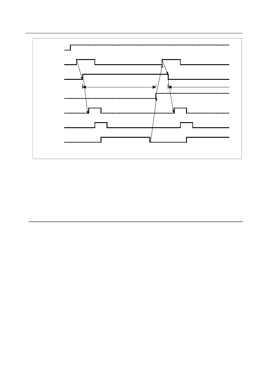
Fig. 16.1.1 (m) Timing chart of buffering related signals 

 
Buffering is disabled, regardless of the buffering disable signal EMBUFg, for the following commands: 
(1)  Skip-feed per minute (EC0g to EC6g : 03h) 
(2)  Reference position return (EC0g to EC6g : 05h) 
(3)  1st reference position return (EC0g to EC6g : 07h) 
(4)  2nd reference position return (EC0g to EC6g : 08h) 
(5)  3rd reference position return (EC0g to EC6g : 09h) 
(6)  4th reference position return (EC0g to EC6g : 0Ah) 
(7)  Machine coordinate system selection (EC0g to EC6g : 20h) 
 

(18) Controlled axis selection status signal *EAXSL <F129.7> 

  [Classification]  Output signal, path-by-path signal 
 

[Function]  Indicates whether PMC axis control is being exercised. 


[Operation]  When this signal is set to “0”, controlled axis selection signals EAX1 to EAX8 can be 

changed. 
This signal is set to “1” in the following cases: 
(1)  When the tool is moving along a PMC-controlled axis 
(2)  When a block is being read into a buffer 
(3)  When the servo-off signal ESOFg is set to “1” 
When this signal is set to “1”, controlled axis selection signals EAX1 to EAX8 cannot be 
changed. Any attempt to change these signals results in the output of an alarm PS0139, 
“CANNOT CHANGE PMC CONTROL AXIS”. 
If an attempt to change signals EAX1 to EAX8 is made when servo-off signal ESOFg is 
“1”, an alarm PS0139 occurs and cannot be released simply by setting reset signal 
ECLRg to “1”. In such a case, restore signals EAX1 to EAX8 or set servo-off signal 
ESOFg to “0” before setting reset signal ECLRg to “1”. When a command is issued for 
any of the four groups with PMC axis control, signal *EAXSL is set to “1” to disable axis 
selection. Thus, changing signals EAX1 to EAX8 results in the output of an alarm 
PS0139. For groups for which commands are not issued, however, axis selection is 
enabled if bit 5 (DSL) of parameter No. 8004 is set accordingly. 


B-64693EN-1/01


16. PMC CONTROL FUNCTION


- 2547 - 

(19) In-position signal EINPg <F130.0, F133.0, F136.0, F139.0> 

  [Classification]  Output signal, group-by-group signal 
 

[Function]  Indicates the in-position state. 


[Operation]  This signal is set to “1” when the corresponding PMC-controlled axis is in the in-position 

state. 
When the tool is decelerated, in-position check is performed to disable the next command 
until the tool enters the in-position area. The in-position check, however, can be skipped 
using bit 6 (NCI) of parameter No. 8004 to reduce the cycle time. 


NOTE 


When the axis is fed at a very low speed, the in -position signal 
might turn to “1”.   


(20) Following zero checking signal    ECKZg <F130.1, F133.1, F136.1, F139.1> 

  [Classification]  Output signal, group-by-group signal 
 

[Function]  Indicates the following zero state. 


[Operation]  This signal is set to “1”  when following zero check or in-position check is being 

performed for the corresponding PMC-controlled axis. 
The following zero state means that the acceleration/deceleration delay amount is zero. 


(21) Alarm signal EIALg <F130.2, F133.2, F136.2, F139.2> 

  [Classification]  Output signal, group-by-group signal 
 

[Function]  Indicates the alarm state related to PMC axis control. 


[Operation]  This signal is set to “1”  when a servo alarm, overtravel alarm, or alarm PS0130,  “NC 

AND PMC AXIS ARE CONFLICTED”  or PS0139,  “CANNOT CHANGE PMC 
CONTROL AXIS” occurs for the corresponding PMC-controlled axis. This signal is set 
to “0“ when the reset signal ECLRg is set to “1” after the alarm is released, as described 
below. 
Servo alarm 
 

Eliminate the cause of the alarm, then reset the CNC. 

Overtravel alarm 
 

Move the tool into the area within the stored stroke limit, then reset the CNC. 


The following commands can be used to move the tool into the area within the 
stored stroke limit during an overtravel alarm: 
(1)  Rapid traverse (EC0g to EC6g : 00h) 
(2)  Cutting feed - feed per minute (EC0g to EC6g : 01h) 
(3)  Cutting feed - feed per rotation(EC0g to EC6g : 02h) 
(4)  Continuous feed (EC0g to EC6g : 06h) 
(5)  External pulse synchronization - first manual handle (EC0g to EC6g : 0Dh) 
(6)  External pulse synchronization - second manual handle (EC0g to EC6g : 0Eh) 
(7)  External pulse synchronization - third manual handle (EC0g to EC6g : 0Fh) 

Alarm (PS0130, PS0139) 
 

Reset the CNC. 
See "Alarms and messages" for details. 


Reset signal ECLRg cannot be used to reset the CNC in the above cases. Use the reset 
button on the setting panel, external reset signal ERS, or emergency stop signal *ESP. 
 
Even if an alarm occurs on an axis not related to the group, alarm signal EIALx does not 
generally change from “0” to “1”. 


16. PMC CONTROL FUNCTION


B-64693EN-1/01


- 2548 - 

(22) Axis moving signal EGENg <F130.4, F133.4, F136.4, F139.4> 

  [Classification]  Output signal, group-by-group signal 
 

[Function]  Indicates the state of movement on an axis. 


[Operation]  This signal is set to “1” when the tool is moving along the corresponding PMC-controlled 

axis according to commands such as rapid traverse (EC0g to EC6g: 00h) and cutting feed 
(EC0g to EC6g: 01h). 
When the dwell command (EC0g to EC6g: 04h) is specified, this signal remains to be set 
to “0”. 


NOTE 


This signal is set to “0” when distribution for the axis is completed 
(the signal is set to “0” during deceleration). 


(23) Auxiliary function executing signal EDENg <F130.3, F133.3, F136.3, F139.3> 

  [Classification]  Output signal, group-by-group signal 
 

[Function]  Indicates the state of auxiliary function execution. 


[Operation]  When an auxiliary function (EC0g to EC6g: 12h) is specified by the PMC, this signal is 

set to “1”  during the period from when auxiliary function codes EID0g  to EID15g are 
sent to auxiliary function code signals EM11g to EM48g until the auxiliary function 
completion signal EFINg is returned. 
Fig. 16.1.1 (n), "Timing chart of auxiliary function related signals" shows the timing chart 
of command operation. 
TMF and TFIN in the table are set in parameters Nos. 3010 and 3011. 


Command block 


(input) 


EM11g to EM48g 


(output) 


EMFg, EMF2g, EMF3g 


(output) 


EFINg 


(input) 


EDENg 


(output) 


Auxiliary function command 

TMF 

TFIN 

Next command 


Fig. 16.1.1 (n) Timing chart of auxiliary function related signals 

B-64693EN-1/01


16. PMC CONTROL FUNCTION


- 2549 - 

(24) Negative-direction overtravel signal EOTNg <F130.6, F133.6, F136.6, F139.6> 
(25) Positive-direction overtravel signal EOTPg <F130.5, F133.5, F136.5, F139.5> 

  [Classification]  Output signal, group-by-group signal 
 

[Function]  Indicates the overtravel state. 


[Operation]  These signals are set to “1” when an overtravel alarm is detected. When the stroke limit in 

the negative direction is exceeded, signal EOTNg is set to “1”. When the stroke limit in 
the positive direction  is exceeded, signal EOTPg is set to “1”. Simultaneously, alarm 
signal EIALg is set to “1”. 


  These signals are set to “0“ when the overtravel alarm is released and reset signal ECLRg 

is set to “1”. See "Alarm signal EIALg" for details of how to release an overtravel alarm. 
 

(26) Feedrate override signals *EFOV0g to *EFOV7g <G151 (, G163, G175, G187)> 

  [Classification]  Input signal, path-by-path signal (group-by-group signal) 
 

[Function]  Applies cutting override. 


[Operation]  Like the CNC's feedrate override signals *FV0 to *FV7, these signals can be used to 

select the override for the cutting feedrate, in steps of 1% from 0 to 254%, independently 
of the CNC using the bit 2 (OVE) of parameter No. 8001. 
These signals form an eight-bit binary code and correspond to the override value as 
follows: 

=

×

=

7

0

i

i

%

2


 value

Override

Vi


Vi = 0 when signal *EFOVi is “1” 
Vi = 1 when signal *EFOVi is “0” 
That is, each signal has the following significance: 
*EFOV7  = 128%, 

*EFOV3    = 8% ,   

*EFOV6  =  64%, 

*EFOV2    = 4% ,   

*EFOV5  =  32%, 

*EFOV1    = 2% , 

*EFOV4  =  16%, 

*EFOV0  = 1% 

When all signals are set to “0”, the override is regarded as being 0%, as well as when all 
signals are “1”. 
Bit 5 (IFV) of parameter No. 8005 is used to determine whether these signals are 
path-by-path signals or group-by-group signals. 
When the IFV parameter is set to 0, these signals are path-by-path signals. When the IFV 
parameter is set to 1, these signals are group-by-group signals. 
 

(27) 1% step rapid traverse override signals *EROV0g to *EROV7g<G151 (, G163, 

G175, G187)> 

  [Classification]  Input signal, path-by-path signal (group-by-group signal) 
 

[Function]  These signals use the same addresses as the feedrate override signals. When bit 1 (OVR) 

of parameter No. 8013 is set to 1, these signals are used for rapid traverse override. 


[Operation]


When bit 2 (OVE) of parameter No. 8001 is set to 1 and bit 1 (OVR) of parameter No. 
8013 is set to 1, these signals can be used to select the override for the rapid traverse rate, 
in steps of 1% from 0% to 100%, independently of the CNC. The override is clamped to 
100%. 
Each corresponding signal has the following significance: 
 

*EROV7 = 100% 

*EROV3 = 8% 


*EROV6 = 64% 

*EROV2 = 4% 


*EROV5 = 32% 

*EROV1 = 2% 


*EROV4 = 16% 

*EROV0 = 1% 

For example, to set an override of 5%, set signals *EFOV7 to *EFOV0 to 11111010, 
which corresponds to a binary code of 00000101. 
 
When bit 7 (IFH) of parameter No. 11850 is set to 0, these signals are used as 
path-by-path signals. When the bit is set to 1, they are used as group-by-group signals. 

16. PMC CONTROL FUNCTION


B-64693EN-1/01


- 2550 - 

NOTE 


When all signals are set to “0”, an override of 100% is assumed, 
while an override of 0% is assumed for *EFOVg. 


(28) Override cancellation signal EOVCg <G150.5 (G162.5, G174.5, G186.5)> 

  [Classification]  Input signal, path-by-path signal (group-by-group signal) 
 

[Function]  Disables override. 


[Operation]  When override is enabled, independently of the CNC, by setting the bit 2 (OVE) of 

parameter No. 8001, setting this signal to “1”  fixes the cutting feed override to 100%. 
This signal does not affect the rapid traverse override. 
Bit 5 (IFV) of parameter No. 8005 is used to determine whether these signals are 
path-by-path signals or group-by-group signals. 
When the IFV parameter is set to 0, these signals are path-by-path signals. When the IFV 
parameter is set to 1, these signals are group-by-group signals. 
 

(29) Rapid traverse override signals EROV1, EROV2 <Gn150.0,1> 

  [Classification]  Input signal, path-by-path signal 
 

[Function]  Applies rapid traverse override. 


[Operation]  These signals can be used to select the override for the rapid traverse rate, independently 

of the CNC, by setting of the bit 2 (OVE) of parameter No. 8001. 


Rapid traverse override signals 

Override value 

EROV2 

EROV1 


100% 

50% 
25% 

F0 

F0 is the minimum feedrate specified with parameter No. 1421. 


(30) Dry run signal EDRN <G150.7> 
(31) Manual rapid traverse selection signal ERT <G150.6> 

  [Classification]  Input signal, path-by-path signal 
 

[Function]  Applies dry run, or chooses whether to apply dry run. 


[Operation]  These signals can be used to perform dry run or manual rapid traverse, independently of 

the CNC, by setting the bit 2 (OVE) of parameter No. 8001. When the dry run signal 
EDRN is set to “1”, the specified rapid traverse rate and cutting feedrate are ignored and 
the tool moves at the dry run speed (set in parameter No. 1410) multiplied by the 
specified  manual feedrate override. Bit 3 (RDE) of parameter No. 8001 can be used to 
specify whether to enable or disable dry run for rapid traverse. 
When the manual rapid traverse selection signal ERT is set to “1” during dry run, the tool 
moves at the rapid traverse rate for rapid traverse and at the maximum jog feedrate for 
cutting feed. When the signal is set to “0”, the tool moves at the jog feedrate. When the 
dry run signal EDRN is set to “0”, the specified rapid traverse rate or cutting feedrate is 
restored. 
 

Manual rapid traverse   

select signal 

Command from PMC 

At rapid traverse 

At Cutting feed 

Rapid traverse rate 

Cutting feedrate 

Dry run feedrate x JV (NOTE) 

or Rapid traverse rate * 

Dry run feedrate x JV (NOTE) 

Dry run feedrate 

×

 JV when bit 3 (RDE) of parameter No. 8001 is 1. Rapid traverse 

rate when parameter RDE is 0. 

B-64693EN-1/01


16. PMC CONTROL FUNCTION


- 2551 - 

NOTE 


When bit 1 (JOV) of parameter No. 1402 is set to 1, the manual 
feedrate override signal *JV is not applied, but the dry run feedrate 
is just applied. 


(32) Override 0% signal EOV0 <F129.5> 

  [Classification]  Output signal, path-by-path signal 
 

[Function]  Indicates whether the override value is 0%. 


[Operation]  This signal is set to “1” when the feedrate override is 0%. 


(33) Skip signal ESKIP <X0004.6>, ESKIP

#2

 <X0013.6>, ESKIP

#3

 <X0011.6> 

  [Classification]  Direct input signal, path-by-path signal 
 

[Function]  Applies skip. 


[Operation]  When this signal is set to “1”  during execution of the skip cutting command, the block 

being executed is immediately stopped and the next block is executed. This signal is 
unique during PMC axis control. Bit 7 (SKE) of parameter No. 8001 can be used to select 
whether to use signal SKIP, which is the common skip signal for the PMC and CNC, or 
PMC-specific skip signal ESKIP. 
 
This skip signal is valid for those axes that are assigned to path 1 to path 3. 
For those axes that are assigned to path 1, ESKIP (X004.6) is valid. 
For those axes that are assigned to path 2, ESKIP

#2

 (X013.6) is valid. 

For those axes that are assigned to path 3, ESKIP

#3

 (X011.6) is valid. 

This skip signal cannot be used for those axes that are assigned to path 4. 


(34) Distribution completion signals EADEN1 to EADEN32 <F112> 

  [Classification]  Output signal, axis-by-axis signal 
 

[Function]  Indicates the state of distribution based on PMC axis control. 


[Operation]  These signals are set to “0” when the tool is moving with a command from the PMC. The 

signals are set to “1” when the tool is not moving, except when it is stopped by an axis 
control temporary stop signal ESTPg during the execution of a move command. 


(35) Buffer full signal EABUFg <F131.1, F134.1, F137.1, F140.1> 

  [Classification]  Output signal, group-by-group signal 
 

[Function]  Indicates the PMC axis control command buffering state. 


[Operation]  When the group input buffer holds a command block, this signal is set to “1”. When no 

command is buffered, this signal is set to “0”.   


(36) Controlling signals EACNT1 to EACNT32 <F182> 

  [Classification]  Output signal, axis-by-axis signal 
 

[Function]  Indicates that PMC axis control is being exercised. 


[Operation]  When the control axis selection status signal *EAXSL is set to “1”, the bit signal 

corresponding to an axis being controlled is set to “1”. 
A bit signal is set to “1“ also when the servo-off signal ESOFg is set to “1”. 


(37) Accumulated zero check signal 
    ELCKZg <G142.1, G154.1, G166.1, G178.1> 

  [Classification]  Input signal, group-by-group signal 
 

[Function]  Makes an accumulated zero check. 


[Operation]  Setting this signal to “1” causes an accumulated zero check between blocks to be made at 

a subsequent cutting feed command. The accumulated zero state means that the 
acceleration/deceleration delay amount is zero. 

16. PMC CONTROL FUNCTION


B-64693EN-1/01


- 2552 - 

(1)  Cutting feed - feed per minute (EC0g to EC6g: 01h) 
(2)  Cutting feed -feed per rotation (EC0g to EC6g: 02h) 
(3)  Cutting feed - sec/block (EC0g to EC6g : 21h) 
This signal can be used, for example, with the chopping function. 


(38) Torque control mode signal 
    TRQM1 to TRQM8 <F190> 

  [Classification]  Output signal, axis-by-axis signal 
 

[Function]  Indicates an axis in the torque control mode. 


[Operation]  When this signal is set to “1”, which axis is placed in the torque control mode by the 

torque control command (EC0g to EC6g: 11h) based on PMC axis control is indicated. 


Signal detail (Related signals) 

The signals related to PMC axis control are detailed below. 
The [Function] field and [Operation] field provide descriptions related to PMC axis control. For the 
general functions of the signals, see the description of each signal.   
 

(1) External deceleration signals 1   

*+ED1 to *+ED8 <G118>, *-ED1 to *-ED8 <G120> 

(2) External deceleration signals 2   

*+ED21 to *+ED28 <G101>, *-ED21 to *-ED28 <G103> 

(3) External deceleration signals 3   

*+ED31 to *+ED38 <G107>, *-ED31 to *-ED38 <G109> 

(4) External deceleration signals 4   

*+ED41 to *+ED48 <G341>, *-ED41 to *-ED48 <G342> 

(5) External deceleration signals 5   

*+ED51 to *+ED58 <G343>, *-ED51 to *-ED58 <G344> 

  [Classification]  Input signal, axis-by-axis signal 
 

[Function]  Decelerates the movement along a specified axis to a parameter-set feedrate. 


[Operation]  While a signal is set to “0”  for an axis, the feedrate along the axis in the specified 

direction can be forcibly decelerated to a certain feedrate (external deceleration feedrate) 
set by a parameter (dependent on the type of command). 
If the feedrate is lower than the external deceleration feedrate, however, the specified 
feedrate continues to be used. 
The feedrate for other axes with these signals not set to “0” is not affected. 
For details, refer to the specifications of the external deceleration function. 
A signal is available for each controlled axis and for each direction. Each signal name 
includes the sign + or - for direction indication, and the number at the end of each signal 
name indicates a controlled axis number. These signals are shared by the CNC. 


* x ED y z 


1 :  Feed along the first axis is decelerated. 
2 :  Feed along the second axis is decelerated. 
3 :  Feed along the third axis is decelerated. 
 

None:  Follows external deceleration setting 1. 
2 : 

Follows external deceleration setting 2. 

3 : 

Follows external deceleration setting 3. 

4 : 

Follows external deceleration setting 4. 

5 : 

Follows external deceleration setting 5. 

B-64693EN-1/01


16. PMC CONTROL FUNCTION


- 2553 - 


+ :  Feed in the positive direction is decelerated. 
- : 

Feed in the negative direction is decelerated. 

 
When any of the following axis control command is specified while the bit 0 (EDC) of 
parameter No. 8005 is held at 1, the external deceleration function becomes effective: 
(1)  Rapid traverse 


(EC0g to EC6g : 00h) 

(2)  Cutting feed - feed per minute     

(EC0g to EC6g : 01h) 

(3)  Reference position return 


(EC0g to EC6g : 05h) 

(4)  Continuous feed 


(EC0g to EC6g : 06h) 

(5)  First reference position return 


(EC0g to EC6g : 07h) 

(6)  Second reference position return   

(EC0g to EC6g : 08h) 

(7)  Third reference position return   

(EC0g to EC6g : 09h) 

(8)  Fourth reference position return   

(EC0g to EC6g : 0Ah) 

(9)  Machine coordinate system selection 

(EC0g to EC6g : 20h) 

(10)  Cutting feed - sec/block 


(EC0g to EC6g : 21h) 


For each command above, the external deceleration feedrate settings for axis-by-axis 
rapid traverse (parameters Nos. 1427, 1441, 1444, 12752, and 12755) are valid. 
To cutting feed -  feed per minute (EC0g to EC6g: 01h) and cutting feed -  sec/block 
(EC0g to EC6g: 21h) as well, the settings for rapid traverse are applied instead of the 
external deceleration feedrate settings for cutting feed (parameters Nos. 1426, 1440, 1443, 
12751, and 12754). 


(6) 1% rapid traverse override select signal HROV <G96.7> 

  [Classification]  Input signal, path-by-path signal 


(7) 1% rapid traverse override signal *HROV0 to *HROV6 <G96.0 to G96.6> 

  [Classification]  Input signal, path-by-path signal 
 

[Function]  Enables override to be applied in steps of 1%. Shared by the CNC. 


[Operation]  If the 1% rapid traverse override select signal HROV <G96.7> is set to “1”  when bit 2 

(OVE) of parameter No. 8001 is set to 0, rapid traverse override can be specified in steps 
of 1% by using the 1% rapid traverse override signals *HROV0 to *HROV6 <G96.0 to 
G96.6>. 


(8) 0.1% rapid traverse override select signal FHROV <G353.7> 

  [Classification]  Input signal, path-by-path signal 


(9) 0.1% rapid traverse override signal   

*FHRO0 to *FHRO9 <G352.0 to G352.7, G353.0 to G353.1> 

  [Classification]  Input signal, path-by-path signal 
 

[Function]  An override can be applied in steps of 0.1%. This signal is used with the CNC as well.   


[Operation]  If bit 2 (OVE) of parameter No. 8001 is set to 0, the 0.1% rapid traverse override signals 

*FHRO0 to *FHRO9 <G352.0 to G352.7, G353.0 to G353.1> enable a rapid traverse 
override to be specified in steps of 0.1% when the 1% rapid traverse override select signal 
HROV <G96.7> and the 0.1% rapid  traverse override select signal FHROV <G353.7> 
are set to “1”. 

(10) Rapid traverse override signal ROV1 <G14.0>, ROV2 <G14.1> 

  [Classification]  Input signal, path-by-path signal 
 

[Function]  Overrides the rapid traverse rate. Shared by the CNC. 


[Operation]  This signal is a two-bit code signal, and sets an override value as indicated Table 16.1.1 

(aa). 


Content      ..     322      323      324      325     ..