FANUC Series 0i-MODEL F Plus. CONNECTION MANUAL (FUNCTION) - page 322
 

  Index      Manuals     FANUC Series 0i-MODEL F Plus. CONNECTION MANUAL (FUNCTION) B-64693EN-1/01


Search            copyright infringement  


Content      ..     320      321      322      323     ..


FANUC Series 0i-MODEL F Plus. CONNECTION MANUAL (FUNCTION) - page 322


16. PMC CONTROL FUNCTION


B-64693EN-1/01


- 2530 - 

Axis control block data 

Signal abbreviation 

Signal address (group 1) 

Data 

EC0g to EC6g 

G143.0 to G143.6 

Speed command (10h) 

EIF0g to EIF15g 

G144,145 

Continuous feedrate 


Continuous feedrate 

Set the speed of the servo motor with a binary code. 
Set a positive value when the servo motor rotates in the forward direction. Set a negative value (two's 
complement) when the servo motor rotates in the reverse direction. 
If a new servo motor speed is set as a feedrate, and the logical state of the axis control command read 
signal EBUFg is reversed, the servo motor is accelerated or decelerated to the new speed. 
 

Valid data range 

Unit 

-32768 to +32767 

min

-1


Related parameters 


Parameter No. 8028 


Parameter No. 8029 


Parameter No. 8032 


NOTE 

1  The following feedrate error can occur: 


Gear 

Motor 

Axis 

(b) 

Speed command 

Amplifier 

Detector 

(a) 


(a)  With the speed command based on PMC axis control, a servo motor speed 

is specified as a feedrate. So, in order to command a feedrate for an axis 
when a gear is used between the axis and servo motor, the desired feedrate 
for the axis needs to be converted to a servo motor speed. A feedrate must 
be specified using an integer, so that when it is converted to a servo motor 
speed, a rounding error can occur. 

(b)  The minimum unit of feedrate is given by the expression below. An integer 

must be specified. No finer value may be specified. 
Fmin = P 

÷

 1000 (mm/min) 

A calculation is made according to IS-B. 
Fmin: Minimum feedrate unit 
P : Number of pulses per revolution of a detector for speed feedback 
A speed is command according to the expression below. 
F = N 

×

 P 

÷

 1000 (mm/min) 

A calculation is made according to IS-B. 
F : Speed command (integer) 
N : Servo motor speed (min

-1

P : Number of pulses per revolution of a detector for speed feedback 

2  In the speed command mode, a speed after acceleration/deceleration is 

command for the servo control section. At this time, a position control loop gain 
is invalid. 

3  Machine lock is disabled for the speed command. 


B-64693EN-1/01


16. PMC CONTROL FUNCTION


- 2531 - 

Speed command and position control 

The PMC axis can be moved at a constant speed by performing the speed command of PMC axis control 
through position loop control, that is, outputting the command pulses corresponding to a rotation speed to 
servo position control instead of outputting rotation speed data to the amplifier. 
Set the FS16i specification (set bit 2 (VCP) of parameter No. 8007 to 1) and specify either speed loop 
control or position loop control is used for speed command of PMC  axis control using bit 4 (EVP) of 
parameter No. 8005. 
When speed command with position control(bit 4 (EVP) of parameter No. 8005 and bit 2 (VCP) of 
parameter No. 8007 are set to 1) is selected and uses acceleration/ deceleration, the linear 
acceleration/deceleration expanded parameter for PMC axis control speed command continuous feed (bit 
0 (PTC) of parameter 12730) must be set to 1, and set the linear acceleration/deceleration using following 
parameters. 

Parameter(No.8028):Time constant 1 of linear acceleration/deceleration in feedrate control command 
under PMC axis control: Unit [msec/1000[min

-1

]] 

Parameter(No.12731):Time constant 2 of linear acceleration/deceleration in feedrate control command 
under PMC axis control :Unit [msec/1000[min

-1

]] 

Parameter(No.12732):Time constant 3 of linear acceleration/deceleration in feedrate control command 
under PMC axis control :Unit [msec/1000[min

-1

]] 

Parameter(No.12733):Time constant 4 of linear acceleration/deceleration in feedrate control command 
under PMC axis control :Unit [msec/1000[min-

1

]] 

Parameter(No.12734):Time constant 5 of linear acceleration/deceleration feedrate control command 
under PMC axis control :Unit [msec/1000[min

-1

]] 

Parameter(No.12735):1st feedrate for changing time constant of continuous feed operation based on a 
feedrate control command in PMC axis control :Unit [min

-1

Parameter(No.12736):2nd feedrate for changing time constant of continuous feed operation based on a 
feedrate control command in PMC axis control :Unit [min

-1

Parameter(No.12737):3rd feedrate for changing time constant of continuous feed operation based on a 
feedrate control command in PMC axis control :Unit [min

-1

Parameter(No.12738):4th feedrate for changing time constant of continuous feed operation based on a 
feedrate control command in PMC axis control :Unit [min

-1

When the bell-shaped acceleration/deceleration is used, set the time constant to parameter (No.8029) in 
addition to the setting of the linear acceleration/deceleration.   
For position control (bit 4 (EVP) of parameter No. 8005 is 1), override is enabled. 
Set parameter No. 8040 for each axis to the amount of travel per revolution of the motor in terms of the 
minimum travel unit and convert speed commands to position commands using this value. 
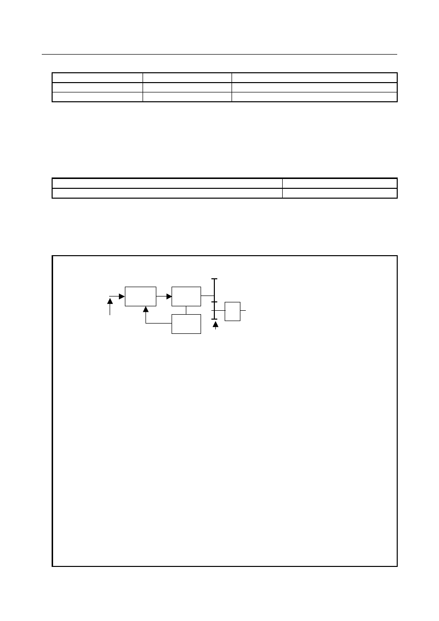
As shown in the following block diagram (Fig.  16.1.1  (k)), rotation speed data is not output to the 
amplifier and the command pulses corresponding to a rotation speed are output to servo position control. 


Block diagram 

Command 

pulse 

CMR 

Position  

control 

Servo 

amplifier 

Motor   


Detector 


Fig. 16.1.1 (k) 


Related parameters


Bit 4 (EVP) of parameter No. 8005 


Bit 2 (VCP) of parameter No. 8007 


Parameter No. 8040 


Bit 0 (PTC) of parameter No. 12730 


Parameter No. 12731 


Parameter No. 12732 

16. PMC CONTROL FUNCTION


B-64693EN-1/01


- 2532 - 


Parameter No. 12733 


Parameter No. 12734 


Parameter No. 12735 


Parameter No. 12736 


Parameter No. 12737 


Parameter No. 12738 


NOTE 

1  The commanded control axis to be controlled needs to be set as a rotation axis 

in bit 0 (ROTx) of parameter No. 1006. 

2  When the FS16i specification (bit 2 (VCP) of parameter No. 8007 is 1) and 

speed control (bit 4 (EVP) of parameter No. 8005 is 0) are specified, coordinates 
are not updated. 
After execution, the following signal is set to 0 and the position is lost. 
-  Reference position establishment signal ZRFx<F120> 


After execution of speed command, establish the reference position. 

3  When the FS16i specification (bit 2 (VCP) of parameter No. 8007 is 1) and 

position control (bit 4 (EVP) of parameter No. 8005 is 1) are specified, 
coordinates are updated. 

4  Only when the FS16i specification (bit 2 (VCP) of parameter No. 8007 is 1) and 

position control (bit 4 (EVP) of parameter No. 8005 is 1) are specified, feedrate 
override is enabled. 

5  After the execution of speed command, to execute a move command in an NC 

block, execute the method (2) of CAUTION 9 in the item "Caution" described in 
the end of chapter "PMC CONTROL FUNCTION". 

6  Flexible synchronization control cannot be used together with speed command in 

PMC axis control (Speed control). 


(17) Torque control ( 11h ) 

This command performs a continuous feed operation based on torque control. 
 
With this command, position control on a PMC control axis can be switched to torque-based control. The 
servo motor outputs torque exactly as specified by the NC. 
 

Axis control block data 

Signal abbreviation 

Signal address (group 1) 

Data 

EC0g to EC6g 

G143.0 to G143.6 

Torque control command (11h) 

EIF0g to EIF15g 

G144,145 

Maximum feedrate 

EID0g to EID31g 

G146 to 149 

Torque data 


Maximum feedrate 

Command a maximum feedrate during torque control by using the unit min

-1

When there is no torque generation target or the feedrate exceeds the commanded  value during torque 
control, the alarm SV0422, “EXCESS VELOCITY IN TORQUE” is issued. 
When updating the maximum feedrate during torque control set in the torque control mode, set new data 
on the signals and reverse the logical state of the axis control command read signal EBUFg. 
 

Valid data range 

Unit 

1 to +32767 

min

-1


NOTE 


When a linear motor is used, the unit of data is cm/min. 

B-64693EN-1/01


16. PMC CONTROL FUNCTION


- 2533 - 

Torque data 

Command torque data. 
Command  a positive value when the torque direction is positive. Command  a negative value when the 
torque direction is negative. 
When updating the torque data set in the torque control mode, set new data on the signals and reverse the 
logical state of the axis control command read signal EBUFg. 
 

Valid data range 

Unit 

-999999999 to +999999999 (9-digit) 

0.00001 Nm 


NOTE 


When a linear motor is used, the unit of data is 0.001N. 

 
(1)  Switching from position control to torque control 

(a)  Torque control axis setting 

Using bit 7 (TRQ) of parameter No. 2007, set whether an axis is to be placed under  torque 
control. Moreover, for an axis to be placed under torque control, set the torque constant 
parameter No. 2105. The standard value of the motor is automatically set in this parameter 
when the power is turned on after setting bit 1 (DGP) of parameter No. 2000 to 0. 

(b)  Position management in the torque control mode 

Whether to perform follow-up operation in the torque control mode can be chosen using bit 4 
(TQF) of parameter No. 1803. 
If follow-up operation is performed (with bit 4 (TQF) of parameter No. 1803 set to 1), position 
control is exercised, regardless of whether the torque control mode is set. 
If follow-up operation is not performed (with bit 4 (TQF) of parameter No. 1803 set to 0), the 
operation depends on whether to update the error counter (bit 1 (TRE) of parameter No. 1805). 
If the error counter is updated (with bit 1 (TRE) of parameter No. 1805 set to 0), the alarm 
SV0423,  “EXCESS ERROR IN TORQUE”  is issued when the value of the error counter 
exceeds the value set in parameter No. 1885. At the time of switching back to position control, 
follow-up operation is performed. 
If the error counter is not updated (with bit 1 (TRE) of parameter No. 1805 set to 1), no errors 
are accumulated, so that no servo alarm is issued. However, when the maximum allowable 
speed is exceeded, the alarm SV0422, “EXCESS VELOCITY IN TORQUE” is issued. 
When this setting is selected, a reference position return operation is required to switch back to 
position control. 
 
Except when bit 4 (TQF) of parameter No. 1803 is set to 0, and bit 1 (TRE) of parameter No. 
1805 is se to 1, the CNC always exercises position control even in the torque control mode. So, 
no reference position return operation needs to be performed even at the time of switching from 
torque control to position control. 

(c)  Movement direction and speed in the torque control mode 

In the torque control mode, the output of torque commanded  by the axis control data signals 
EID0g to EID31g is attempted. However, when there is no torque generation target or the 
output has not reached the commanded  torque data yet, a movement is made in the same 
direction as in the case of position control according to the +/- sign of torque data. When the 
move speed exceeds the commanded value, the alarm SV0422 is issued. 

(d)  Timing of switching to torque control 

Switching to the torque control mode from another mode occurs when the position deviation is 
decreased to within the in-position width. 

(e)  In the torque control mode, the torque control mode signal TRQM1 to TRQM8  is set to “1“. 

(For details of this signal, see "Signal detail".) 


16. PMC CONTROL FUNCTION


B-64693EN-1/01


- 2534 - 

(2)  Switching from torque control to position control 

(Torque control mode cancellation) 
 

When any of the following conditions occurs, the torque control mode ends: 
(i)  When the reset signal ECLRg is set to “1” 
(ii)  When a servo alarm is issued 
(iii)  When an OT alarm is issued with an axis placed under torque control 
(iv)  At the time of emergency stop 
(v)  When servo-off occurs due to the servo-off signal ESOFg 

(a)  Timing of torque control cancellation 

The cancellation of torque control based on PMC axis control depends on whether to perform 
follow-up operation as determined by bit 4 (TQF) of parameter No. 1803. 

When follow-up operation is performed (with bit 4 (TQF) of parameter No. 1803 set to 1). 
The torque control mode signal TRQM1 to TRQM8 is set to 0 to return to position control 
immediately when a cancellation condition occurs. The execution then stops when the 
position deviation is decreased to within the in-position width. 

When follow-up operation is not performed (with bit 4 (TQF) of parameter No. 1803 set 
to 0). 
The  torque control mode signal TRQM1 to TRQM8 is set to 0 when a cancellation 
condition occurs. If the error counter is updated (with bit 1 (TRE) of parameter No. 1805 
set to 0), the control mode is switched back to position control when the position deviation 
is decreased to below the value of the cancellation limit parameter No. 1886 after the start 
of follow-up operation. The execution then ends when the position deviation is decreased 
to within the in-position width. If the error counter is not updated (bit 1 (TRE) of 
parameter No. 1805 is set to 1), a reference position return operation must be once 
performed to return to position control. 

(b)  Command after cancellation 

After the torque control mode is canceled, the control mode is switched to normal position 
control. In the torque control mode, position is controlled, so that machine coordinates are not 
shifted. However, a shift occurs between the workpiece coordinates and machine coordinates, 
so that the shift amount needs to be canceled, for example, by executing workpiece coordinate 
system preset. 
After the execution of torque control, to execute a move command in an NC block, execute the 
method (2) of CAUTION 9 in the item "Caution" described in the end of chapter "PMC 
CONTROL FUNCTION". 

 
The Table 16.1.1 (w) indicates the operations dependent on the settings of bit 4 (TQF) of parameter No. 
1803 and bit 1 (TRE) of parameter No. 1805. 


Table 16.1.1 (w) 

Bit 4 (TQF) of 

parameter No. 

1803 

Bit 1 (TRE) of 

parameter No. 

1805 

Position 

control 

Operation in TRQ mode 

Reference 

position 
return(*) 

0/1 

Position control is exercised. 

Not required 

The alarm SV0423 is issued when the error 
counter exceeds the value of parameter No. 1885. 

Not required 

No SV alarm is issued. When the maximum 
allowable speed is exceeded, however, the alarm 
SV0422 is issued. 

Required 

(*)  Whether reference position return operation is required or not when the control mode has been 

switched from torque control back to position control 


B-64693EN-1/01


16. PMC CONTROL FUNCTION


- 2535 - 

TORQUE CONTROL FUNCTION 
Set following parameters about servo function "torque control function" properly. As to the detail of the 
parameters, refer to "FANUC AC SERVO MOTOR 

α

i

 series PARAMETER MANUAL(B-65270EN)". 

Parameter No.2007#7 
Parameter No.2203#4 
Parameter No.2003#3 
Parameter No.2105 

If the parameter No.2007#7 or No.2105 is not set correctly, the alarm (DS1184), “PARAMETER 
ERROR IN TORQUE” occurs. 
 

  CAUTION 

1  If a movement is made along a torque control axis in the torque control mode, 

set bit 4 (TQF) of parameter No. 1803 for follow-up operation to 1. 

2  If a movement has been made along a torque control axis when torque control is 

canceled, a mechanical shock occurs at the time of return to position control. As 
a greater speed is used, a larger shock occurs. So, decelerate to a maximum 
allowable extent or stop before canceling torque control. 

3  When commanding torque control after completion of manual reference position 

return, set the feed direction selection signal to “0“ or switch to a mode other 
than the manual reference position return mode beforehand. 

4  When the control axis selection signal EAXx is switched in the torque control 

mode, the alarm PS0139, “CANNOT CHANGE PMC CONTROL AXIS” is issued. 
Before switching the control axis selection signal EAXx, cancel the torque control 
mode. 

5  In the torque control mode, do not detach a controlled axis with the control axis 

detach signal DTCHx or a setting parameter. 

6  When servo-off occurs, the torque control mode is canceled. However, the 

torque control state remains to be set. So, be sure to set the reset signal ECLRg 
to “1”. 

7  Machine lock is disabled for the torque control command. 
8  In case bit 4 (TQF) of parameter No. 1803 is 0 (Follow-up operation is not 

performed.) and bit 1 (TRE) of parameter No. 1805 is 1 (Servo error counter is 
not updated.), after execution of torque control, establish the reference position. 

9  After the execution of torque control, to execute a move command in an NC 

block, execute the method (2) of CAUTION 9 in the item "Caution" described in 
the end of chapter "PMC CONTROL FUNCTION". 


Related parameters 


Bit 4 (TQF) of parameter No. 1803 


Bit 1 (TRE) of parameter No. 1805 


Parameter No. 1885 


Parameter No. 1886 


Parameters about servo function "torque control function" (See above description) 

 
Related signals 


Control axis detach signal DTCHx <G124> 


(18) Auxiliary function 1 ( 12h ) 
(19) Auxiliary function 2 ( 14h ) 
(20) Auxiliary function 3 ( 15h ) 

Each of these commands performs the same operation as an auxiliary function (M code Function) of the 
CNC.   

16. PMC CONTROL FUNCTION


B-64693EN-1/01


- 2536 - 

Axis control block data 

Signal abbreviation 

Signal address (group 1) 

Data 

EC0g to EC6g 

G143.0 to G143.6 

Auxiliary function command 

(12h for the auxiliary function 1 command) 
(14h for the auxiliary function 2 command) 
(15h for the auxiliary function 3 command) 

EID0g to EID15g 


G146 to 147 

Auxiliary function code 


Auxiliary function code 

Specify an auxiliary function code to be sent to the PMC with a binary code. 
With bit 6 (AUX) of parameter No. 8001, specify a 1-byte or 2-byte code on the signals EID0g to 
EID15g. 
 

Related parameters 


Bit 6 (AUX) of parameter No. 8001 

 
Related signals 


Auxiliary function completion signal EFINg <G142.0> 


Auxiliary function strobe signal EMFg <F131.0> (for auxiliary function 1) 


Auxiliary function 2 strobe signal EMF2g <F131.2> (for auxiliary function 2) 


Auxiliary function 3 strobe signal EMF3g <F131.3> (for auxiliary function 3) 


Auxiliary function code signals EM11g to EM48g <F132, F142> 


Auxiliary function executing signal EDENg <F130.3> 


NOTE 


The same auxiliary function cannot be concurrently executed with some groups 
(For example, command of 12h to 2 groups). Execute a different auxiliary 
function in each group or execute with another group after the auxiliary function 
ends. 


(21) Machine coordinate system selection ( 20h ) 

This command performs the same operation as “G53” of the CNC. 
 
This command performs rapid traverse in the absolute mode to a commanded  position in the machine 
coordinate system. So, this command can be used to move the tool to a specified machine-specific 
position such as a tool change position. 
 

NOTE 

1  When using this command with the T series, cancel tool offset and tool-nose 

radius compensation beforehand. 

2  When using this command with the M series, cancel tool radius compensation, 

tool length compensation, and tool offset beforehand. 

3  Before this command can be specified, a machine coordinate system must be 

set. So, a manual reference position return operation or reference position return 
operation based on G28 needs to be performed at least once after the power is 
turned on. When an absolute-position detector is attached, machine position 
data is stored, so that a reference position return operation is unnecessary after 
the power is turned on. 

4  This command can be specified regardless of the setting (bit 0 (NWZ) of 

parameter No. 8136) of the workpiece coordinate system. 


B-64693EN-1/01


16. PMC CONTROL FUNCTION


- 2537 - 

When the machine coordinate system selection (20h) is commanded with the PMC axis control for the 
rotary axis to which the roll-over function is valid (bit 0 (ROAx) of parameter No.1008 is set to 1), the 
direction of the rotation for an absolute command is as follows.


Bit 4 (R20x) of parameter No.8013 

Bit 1 (RABx) of 

parameter No.1008 

Direction of the shortest path 

Direction of the shortest path 

Direction of sign of the amount of the 

movement to be made 

Direction of sign of the command 

value 


Axis control block data 

Signal abbreviation 

Signal address (group 1) 

Data 

EC0g to EC6g 

G143.0 to G143.6 

Machine coordinate system selection command 

(20h) 

EIF0g to EIF15g 

G144,145 

Rapid traverse rate 

EID0g to EID31g 

G146 to 149 

Machine coordinate value 


Rapid traverse rate 

The specifications of the rapid traverse command (EC0g to EC6g: 00h) are applicable. 
 

Machine coordinate value 

For a linear axis, specify a machine coordinate  value  in the input unit for the axis as an absolute value 
with a binary code. 
Example: For absolute "10000" 

Input unit 

inch 

1.0000 

mm 

10.000 

Output unit 

mm 

25.400 

inch 

0.3937 

 
For a rotation axis, a move direction can be selected with a parameter. 
Set bit 0 (ROAx) of parameter No. 1008 to 1 to enable the rollover function. Then, select the sign of a 
commanded value or the shortcut direction with bit 1 (RABx) of parameter No. 1008. Additionally, the 
amount of travel per revolution needs to be set in parameter No. 1260. 
 

Related parameters 

  Bit 0 (ROTx) of parameter No. 1006 
  Bit 0 (ROAx) of parameter No. 1008 
  Bit 1 (RABx) of parameter No. 1008 
  Parameter No. 1260 
 

(22) Cutting feed-sec/block specification ( 21h ) 

This command performs cutting feed according to a specified period of time.  In the sec/block 
specification, specify a period of time required for ending a block. 
 

Axis control block data 

Signal abbreviation 

Signal address (group 1) 

Data 

EC0g to EC6g 

G143.0 to G143.6 

Cutting feed - sec/block command specification (21h) 

EIF0g to EIF15g 

G144,145 

Cutting feed time 

EID0g to EID31g 

G146 to 149 

Total moving distance 


Cutting feed time 

Specify a period of time required for ending a block. 

   [Unit of data]    

0.1sec 

   [Valid data range]  1 to 32767 


Content      ..     320      321      322      323     ..