FANUC Series 0i-MODEL F Plus. CONNECTION MANUAL (FUNCTION) - page 325
16. PMC CONTROL FUNCTION
B-64693EN-1/01
- 2554 -
Table 16.1.1 (aa)
R
apid traverse override signal
Override value
ROV2
ROV1
0
0
100%
0
1
50%
1
0
25%
1
1
F0 (parameter No. 1421)
(11) First reference position return completion signals ZP1 to ZP8 <F94>
(12) Second reference position return completion signals ZP21 to ZP28 <F96>
(13) Third reference position return completion signals ZP31 to ZP38 <F98>
(14) Fourth reference position return completion signals ZP41 to ZP48 <F100>
[Classification] Output signal, axis-by-axis signal
[Function] Posts that the tool is at the reference position on a controlled axis. Shared by the CNC.
[Operation] The number at the end of a signal name indicates the number of a controlled axis.
Each of these signals is set to “1” when reference position return is completed, and the
tool enters the in-position area.
Each of these signals is set to “0” when a movement is made from the reference position,
an emergence stop occurs, or a servo alarm is issued.
(15) A/B phase detector disconnection alarm ignore signal
NDCAL1 to NDCAL8 <Gn202>
[Classification] Input signal, axis-by-axis signal
[Function] Does not output the A/B phase detector hard disconnection alarm.
[Operation] While this signal is set to “1”, the A/B phase detector hard disconnection alarm is not
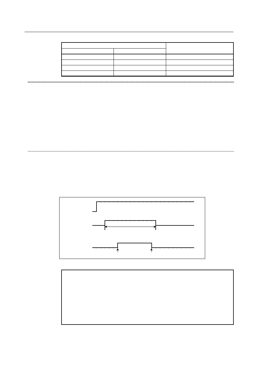
output during speed specification based on PMC axis control. Fig. , "Timing chart of A/B
phase detector disconnection alarm ignore signal" shows a timing chart.
A/B phase detector
disconnection alarm
ignore parameter
HNG (No.2017#4)
NDCALx
(input)
Hard disconnection
Even if hard disconnection
alarm is issued, servo soft
does not notify NC.
Occurs at high speed
Reset by ALR
Fig. 16.1.1 (o) Timing chart of A/B phase detector disconnection alarm ignore signal
NOTE
1 Change the level of this signal from “1” to “0” before switching from
a speed command to a position command.
2 After switching from a speed command to a position command, be
sure to perform a manual reference position return operation before
making a movement on the axis.
3 This function cannot be used when an absolute-position detector is
attached.
4 To enable this signal, set bit 4 (HTN) of parameter No. 2017 to 1.