FANUC Series 0i-MODEL F Plus. CONNECTION MANUAL (FUNCTION) - page 293
 

  Index      Manuals     FANUC Series 0i-MODEL F Plus. CONNECTION MANUAL (FUNCTION) B-64693EN-1/01


Search            copyright infringement  


Content      ..     291      292      293      294     ..


FANUC Series 0i-MODEL F Plus. CONNECTION MANUAL (FUNCTION) - page 293


13. DISPLAY/SET/EDIT


B-64693EN-1/01


- 2298 - 

NOTE 


This parameter is valid when bit 2 (TRA) of parameter No. 3192 is 
set to 1. 


Alarm and message 

Number 

Message 

Description 

SR5303 

TOUCH PANEL ERROR 

The touch panel is not connected correctly, or the touch 
panel cannot be initialized when the power is turned on.   
If bit 2 (TRA) of parameter No. 3192 is set to 1, this message 
is issued also when the touch panel is being kept pressed. 
Correct the cause then turn on the power again. 


Caution 

  CAUTION 


When all memory (SRAM) data is cleared, the soft keys on the touch panel are 
not made usable yet. In this case, the MDI keys (such as the cursor keys and 
page keys) need to be used for setting. 


13.1.5 

External Touch Panel Interface 

Outline 

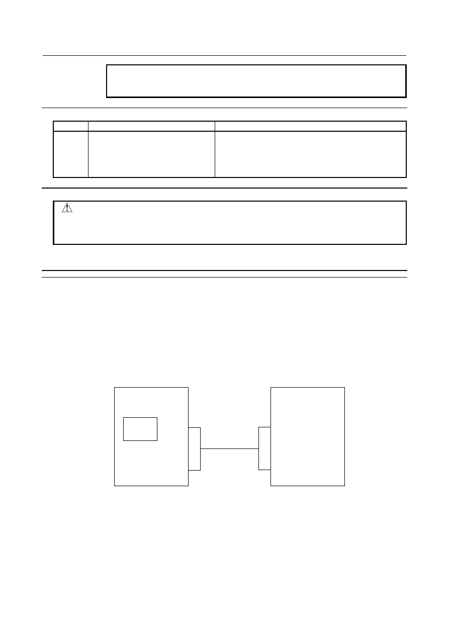
External Touch Panel (called "ETP" below) of SNP-X protocol can be connected with Series 30

i

ETP has functions that can read out/ write in from/to PMC such control signals as input signal(X), output 
signal(Y),  internal  relay(R),  keep relay(K),  data  table(D),  extra relay(E), timer(T),  counter(C),  and the 
function is almost the same as operating panel of machine. 
 
The remarkable function of ETP is drawing function. 
Assignment between drawing and address (signal) can be specified freely. 
For example, the data in data table can be set with the switch on the screen which is designed to assign 
the setting of data table. 


DATA 

Push the switch 

on the screen. 

Data in data 

table is set. 

CNC 

ETP 


B-64693EN-1/01


13. DISPLAY/SET/EDIT


- 2299 - 

Explanation 

  - 

Connection 

RS-232C  serial port 2(JD36A; for the 15”/19”  LCD-mounted type CNC  and LCD-mounted type CNC 
with the is functions, JD54) on main CPU board is used in CNC. 
Cable-A must be based on RS-232C standard, and are prepared by customer. 
 
(1)  Cable-A (connection diagram between JD36A or JD54 on CNC and SIO on ETP.) 


SIO 

Cable-A 

CNC 

ETP 

JD36A or 

JD54 


ETP                     CNC 

SIO(25pin)           JD36A or JD54(20pin)


Shield


03


13


07


03


08


05


15


01


11


07


05


04


02


ER


CD


DR


SG


CS


RS


RD


SD


SG


CS


RS


SD


RD


Cables must be shielded by cable clamp made of metal. 


NOTE 


For the 15”/19” LCD-mounted type CNC and LCD-mounted type CNC with the is 
functions, use pin 04 as SG for cabling. Leave pin 08 open. 


13. DISPLAY/SET/EDIT


B-64693EN-1/01


- 2300 - 

  - 

Power On sequence 

Please turn on the power supply on ETP side first. 
 

  - 

Data of CNC, read / write from ETP 

The following CNC data can be read and written on the ETP side: 
 

Signal type 

30

i

/31

i

/32

i

- B PMC 

First PMC 

Second PMC 

Third PMC 

Input signal to the PMC from the machine 
Note 1 

X0 to X127 

X0 to X127 

X0 to X127 

X200 to X327 

X200 to X327 

X200 to X327 

X400 to X527 

X400 to X527 

X400 to X527 

X600 to X727 

X600 to X727 

X600 to X727 


X1000 to X1127   

X1000 to X1127   

X1000 to X1127 

Output signal from the PMC to the 
machine 

Y0 to Y127 

Y0 to Y127 

Y0 to Y127   

Y200 to Y327 

Y200 to Y327 

Y200 to Y327 

Y400 to Y527 

Y400 to Y527 

Y400 to Y527 

Y600 to Y727 

Y600 to Y727 

Y600 to Y727 


Y1000 to Y1127   

Y1000 to Y1127   

Y1000 to Y1127 

Internal relay 


User area 

R0 to R7999 

R0 to R1499 

R0 to R1499 

Keep relay 


User area 

K0 to K99 

K0 to K19 

K0 to K19 

Data table 

D0 to D9999 

D0 to D2999 

D0 to D2999 

Extra relay 

E0 to E9999 
Note 2 

E0 to E9999 
Note 2 

E0 to E9999 
Note 2 

Timer 


Variable timer 

T0 to T499 

T0 to T79 

T0 to T79 

Counter 


Variable counter 

C0 to C399 

C0 to C79 

C0 to C79 

Fixed counter 

C5000 to C5199 

C5000 to C5039 

C5000 to C5039 


NOTE 

1  These addresses are for read only. 
2  Shared memory of the multi-path PMC. Programs can read and write the same 

value from/to this memory. 


  - 

Protocol 

Only direct command on SNP-X protocol is available in CNC. 
ETP also must use the same protocol and the same command only. 
The process required for writing data more than 3 bytes is the same as 
that lass than 2bytes. 
Please refer the documents of SNP-X protocol for the detail of SNP-X protocol. 
 

  - 

Combined use of the touch panel on the LCD of the CNC and External Touch 
Panel 

ETP cannot be used together with the touch panel on the LCD (excluding Windows CE compatibles) of 
the LCD-mounted type CNC.   
ETP can be  used together with the touch panel on the LCD (excluding Windows CE-enabled 
compatibles) of the stand-alone type CNC.   
 

B-64693EN-1/01


13. DISPLAY/SET/EDIT


- 2301 - 

NOTE 


To use ETP together with the touch panel on the LCD (excluding Windows CE 
compatibles) of the stand-alone type CNC, it is necessary to specify the function 
for the function for touch panel control, and the function for external touch panel 
interface.   


Limitation 

(1)  Only addresses for the PMC set in parameter No. 11310 can be read and written. It is impossible to 

perform reading from and writing to more than one PMC at the same time. 

(2)  ETP is Touch Panel made by DIGITAL Co. Ltd.  ETPs which can be connected with CNC  are as 

follows. 

GP-450E 

GP-550T 

GP-550S 

GP-2000 SERIES 

GP-3000 SERIES 


Parameters 


#7 

#6 

#5 

#4 

#3 

#2 

#1 

#0 

3119 


TPA 


[Input type]  Parameter input 


[Data type]  Bit 


NOTE 


When this parameter is set, the power must be turned off before 
operation is continued. 


#3  TPA

  When the function  for the external touch panel interface is selected, the external touch 

panel interface connection is: 
0: 

Valid. 

1: 

Invalid. 

For an external touch panel (called ETP hereinafter), the RS-232C serial port 2 (JD36A or 
JD54) on the main board of the CNC is used. 
When using ETP, set bit 3 (TPA) of parameter No. 3119 to 0. 
By this setting, JD36A or JD54 is used for ETP, regardless of the setting of I/O 
CHANNEL (I/O device selection) of the existing parameters Nos. 0021 to 0023. 
For other I/O devices, use JD56A and so forth. 
By the setting above, the settings of the existing parameters Nos. 0100 and 0121 to 0123 
become invalid for channel 2 (JD36A or JD54), and the following settings are applied at 
all times: 

Baud rate  

19200 bps 

Stop bit   

1 bit 

Parity check 

Even parity 


13. DISPLAY/SET/EDIT


B-64693EN-1/01


- 2302 - 


#7 

#6 

#5 

#4 

#3 

#2 

#1 

#0 

13101 


TPB 


[Input type]  Parameter input 


[Data type]  Bit 


NOTE 


When this parameter is set, the power must be turned off before 
operation is continued. 


#1  TPB

  Baud rate used with the external touch panel 

0: 

19200 bps is always used. 

1: 

The baud rate with the baud rate number set in parameter No. 0123 for channel 2 is 
used. 

 
As mentioned in the description of bit 3 (TPA) of parameter No. 3119, when TPA is set 
to 0, the baud rate is always set to 19200 bps. 
To allow the baud rate to be changed, set bit 1 (TPB) of parameter No. 13101 to 1. 
This allows the baud rate number set in parameter No. 0123 for channel 2 to be used. 
 

NOTE 


Baud rates that can be set may vary depending on the ETP used. 


11310 


Selection of a PMC that performs read and write operations with an external touch panel 


[Input type]  Parameter input 


[Data type]  Byte 

[Valid data range]  0 to 3 


NOTE 


When this parameter is set, the power must be turned off before 
operation is continued. 

 
This parameter selects an PMC for read and write operations among three PMCs, which 
are the first PMC, second PMC, and third PMC. 
0, 1  : First PMC 
  2  : Second PMC 
  3  : Third PMC 
 

NOTE 


It is impossible to perform read and write operations with more than 
one PMC at the same time. 


B-64693EN-1/01


13. DISPLAY/SET/EDIT


- 2303 - 

13.1.6 

Parameter Check Sum Function 

Overview 

Standard check sum of CNC parameter can be calculated previously and be saved in CNC. In the other 
hand, a parameter check sum is calculated at CNC power-on. This value is compared with the standard 
check sum to check whether there is difference between two values. 
If there are changed parameters, an alarm will occur at next power-on. So the CNC can be averted from 
miss operation such as miss setting of parameter and forgetting to correct the parameters changed 
temporarily. 
 

Explanation 

When bit 0 (CKS) of parameter No. 13730 is changed from 0 to 1, the standard check sum is calculated. 
In the other hand at CNC power-on, a parameter check sum is calculated and its value is compared with 
standard check sum. If two values are different, alarm DS5340,” PARAMETER CHECK SUM ERROR”, 
occurs. 

This alarm is canceled by the operation pressing 


  and 


, but if parameters are not corrected to 

original value, alarm DS5340 will occur again at next check sum comparison at CNC power-on. 
By parameter setting, some parameters can be excluded from check sum. Moreover, there are many 
parameters that CNC system excludes from check sum. (Refer to excluded parameters in this section) 
 

NOTE 


If bit 7 (CSR) of parameter No. 13730 is 1, alarm DS5340 can be canceled only 

by 


  key. 


Parameter check sum information screen 

The parameter check sum information screen shows the value of the standard check sum, the time and 
date when the standard check sum was calculated, and the value of a check sum calculated at power-on. 


Fig. 13.1.6 (a) Parameter check sum information screen (10.4”) 


13. DISPLAY/SET/EDIT


B-64693EN-1/01


- 2304 - 

Parameter check sum setting screen 

  - 

Setting parameters to be excluded 

Setting the number of parameter excluded from check sum on this screen. 
A brief explanation about setting data is shown on the bottom of this frame. 


Fig. 13.1.6 (b) Parameter check sum setting (No.) screen (10.4”) 


Fig. 13.1.6 (c) Parameter check sum setting screen: number setting (15”) 


B-64693EN-1/01


13. DISPLAY/SET/EDIT


- 2305 - 

  - 

Range of excluded parameters 

Setting the range of parameters excluded from check sum. 
A brief explanation about setting data is shown on the bottom of this frame. 


Fig. 13.1.6 (d) Parameter check sum setting (range) screen (10.4”) 


Fig. 13.1.6 (e) Parameter check sum setting screen: range setting (15”) 


Content      ..     291      292      293      294     ..