FANUC Series 0i-MODEL F Plus. CONNECTION MANUAL (FUNCTION) - page 291


  Index      Manuals     FANUC Series 0i-MODEL F Plus. CONNECTION MANUAL (FUNCTION) B-64693EN-1/01


Search            copyright infringement  


Content      ..     289      290      291      292     ..


FANUC Series 0i-MODEL F Plus. CONNECTION MANUAL (FUNCTION) - page 291


13. DISPLAY/SET/EDIT


B-64693EN-1/01


- 2282 - 

Full-size character code list (e) 
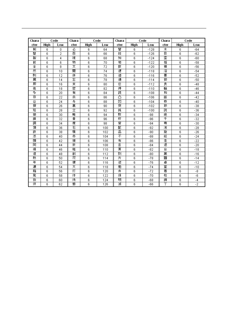


B-64693EN-1/01


13. DISPLAY/SET/EDIT


- 2283 - 

Full-size character code list (f) 


13. DISPLAY/SET/EDIT


B-64693EN-1/01


- 2284 - 

NOTE 

1  The character can be displayed up to the character code just before the 

parameter Nos. 7220 to 7399 is set to 0, in the name of a general-purpose 
switch on the software operator's panel. Therefore, if using the space, specify 
the character code “32” (the space of the half-size character). 


Ex1) When the parameter is set to 0 in the half-size character 

Parameter 

Setting value 

Character 

7220 


7221 

7222 


7223 

7224 


7225 

49 

7226 

50 

7227 

51 


The character string of display : “

” 

 
Ex2) When the parameter is set to 32 (the space of the half-size character) in 

the half-size character 

Parameter 

Setting value 

Character 

7220 


7221 

7222 


7223 

7224 

32 

(space) 

7225 

49 

7226 

50 

7227 

51 


The character string of display : “

  123” 


2  Do not specify the character codes of the blank in the “Full-size character code 

list”. When it is specified, the space of the full-size character or an invalid 
character is displayed. 

 
3  Please specify two spaces of the half-size character to display a space of the 

full-size character. 


B-64693EN-1/01


13. DISPLAY/SET/EDIT


- 2285 - 

Note 

NOTE 

1  Only the modes shown below can be selected by soft switches. When the mode 

for DNC operation is to be required, then, all control switches for mode selection 
should be on the machine operator's panel or a general-purpose soft switch 
should be used to select the mode for DNC operation. 


Soft switches available for mode selection 
-  Manual data input 
-  Automatic operation 
-  Memory edit 
-  Manual handle feed / incremental feed 
-  Jog feed 
-  Manual reference position return 

2  Only one soft switch is available for the protection key. But, four input signals are 

available for protection key (KEY1, KEY2, KEY3 and KEY4).   


Generally, four input signals are simultaneously turned to 1 or 0 according to the 
state of the protection soft switch. 


For a multi-path system, the signals are as follows. These signals are common 
to all paths. 
-  KEYO<F0075.6> 
-  KEY1 to KEY4<G0046.3 to G0046.6> 

3  When the soft switch for feed hold is turned on, output signal SPO is turned to 1, 

and the PMC turns feed hold signal *SP to 0. 


In contrast to the above, when the soft switch for feed hold is turned off, output 
signal SPO is turned 0 and the PMC turns signal *SP to 1. For soft switches 
other than feed hold and general soft switches, when an output signal 
corresponding to a soft switch is turned to 1, the corresponding input signal is 
turned to 1. 


13. DISPLAY/SET/EDIT


B-64693EN-1/01


- 2286 - 

The Table 13.1.2 (a) lists the jog feedrate override values which can be selected by soft switches. 
 

Table 13.1.2 (a) 

Override values (%)


*JV0O to *JV15O 

15 

8  7 

1 1 1 1  

1 1 1 1   1 1 1 1  

1 1 1 1  

0.1 

1 1 1 1  

1 1 1 1   1 1 1 1  

0 1 0 1  

0.14 

1 1 1 1  

1 1 1 1   1 1 1 1  

0 0 0 1  

0.2 

1 1 1 1  

1 1 1 1   1 1 1 0  

1 0 1 1  

0.27 

1 1 1 1  

1 1 1 1   1 1 1 0  

0 1 0 0  

0.37 

1 1 1 1  

1 1 1 1   1 1 0 1  

1 0 1 0  

0.52 

1 1 1 1  

1 1 1 1   1 1 0 0  

1 0 1 1  

0.72 

1 1 1 1  

1 1 1 1   1 0 1 1  

0 1 1 1  

1.0 

1 1 1 1  

1 1 1 1   1 0 0 1  

1 0 1 1  

1.4 

1 1 1 1  

1 1 1 1   0 1 1 1  

0 0 1 1  

2.0 

1 1 1 1  

1 1 1 1   0 0 1 1  

0 1 1 1  

2.7 

1 1 1 1  

1 1 1 0   1 1 1 1  

0 0 0 1  

3.7 

1 1 1 1  

1 1 1 0   1 0 0 0  

1 1 0 1  

5.2 

1 1 1 1  

1 1 0 1   1 1 1 1  

0 1 1 1  

7.2 

1 1 1 1  

1 1 0 1   0 0 1 0  

1 1 1 1  

10.0 

1 1 1 1  

1 1 0 0   0 0 0 1  

0 1 1 1  

14.0 

1 1 1 1  

1 0 1 0   1 0 0 0  

0 1 1 1  

20.0 

1 1 1 1  

1 0 0 0   0 0 1 0  

1 1 1 1  

27.0 

1 1 1 1  

0 1 0 1   0 1 1 1  

0 0 1 1  

37.0 

1 1 1 1  

0 0 0 1   1 0 0 0  

1 0 1 1  

52.0 

1 1 1 0  

1 0 1 1   1 0 1 0  

1 1 1 1  

72.0 

1 1 1 0  

0 0 1 1   1 1 0 1  

1 1 1 1  

100.0 

1 1 0 1  

1 0 0 0   1 1 1 0  

1 1 1 1  

140.0 

1 1 0 0  

1 0 0 1   0 1 0 0  

1 1 1 1  

200.0 

1 0 1 1  

0 0 0 1   1 1 0 1  

1 1 1 1  

 
The Table 13.1.2 (b) lists the feedrate override values which can be selected by soft switches. 
 

Table 13.1.2 (b) 

Override values (%)


*FV0O to *FV7O 

1 1 1 1   1 1 1 1  

10 

1 1 1 1   0 1 0 1  

20 

1 1 1 0   1 0 1 1  

30 

1 1 1 0   0 0 0 1  

40 

1 1 0 1   0 1 1 1  

50 

1 1 0 0   1 1 0 1  

60 

1 1 0 0   0 0 1 1  

70 

1 0 1 1   1 0 0 1  

80 

1 0 1 0   1 1 1 1  

90 

1 0 1 0   0 1 0 1  

100 

1 0 0 1   1 0 1 1  

110 

1 0 0 1   0 0 0 1  

120 

1 0 0 0   0 1 1 1  

130 

0 1 1 1   1 1 0 1  

140 

0 1 1 1   0 0 1 1  

150 

0 1 1 0   1 0 0 1  

160 

0 1 0 1   1 1 1 1  

170 

0 1 0 1   0 1 0 1  

180 

0 1 0 0   1 0 1 1  

190 

0 1 0 0   0 0 0 1  

200 

0 0 1 1   0 1 1 1  


B-64693EN-1/01


13. DISPLAY/SET/EDIT


- 2287 - 

NOTE 


The software operator's panel general-purpose switch function enables the use 
of general-purpose switches 1 to 16. 


Reference item 

Manual name 

Item name 

OPERATOR’S MANUAL (B-64694EN) 

Display and setting of the software operator’s panel 


13.1.3 

8-Level Data Protection Function 

Overview 

Eight operation levels can be set for CNC and PMC operation and eight protection levels can be set for 
various types of CNC and PMC data. 
When various types of CNC and PMC data are changed or output externally, the system compares the 
operation level with the protection level to determine whether change or external output is allowed. 
 

Explanation 

  - 

Operation level 

Eight operation levels can be set for CNC and PMC operation. 
Operation levels 0 to 3 are selected by the memory protection key signal. 
Operation levels 4 to 7 are selected by a password. 


Operation level 

Setting method 

Sample classification 

7 (High) 

Password 

Password 

MTB 

Password 

Dealer, Integrator 

Password 

End user 

Memory protection key signal 

User level (Level 1) 

Memory protection key signal 

User level (Level 2) 

Memory protection key signal 

User level (Level 3) 

0 (low) 

Memory protection key signal 

User level (Level 4) 


NOTE 

1  Once any of operation levels 4 to 7 is set, it is retained (even when the power is 

turned off) until clear operation is performed by the corresponding password. 

2  The initial values of the passwords for operation levels 4 to 6 are shown below. 

-  Operation level 4: "HC3V9ZEP" 
-  Operation level 5: "J72WB8YA" 
-  Operation level 6: "VLR6T92M" 

3  Operation level 7 is reserved for the maintenance of the CNC and PMC. 


  CAUTION 


When this function is provided, the conventional memory protection function is 
disabled. 


When this function is added, the programmer protection function of the PMC is 
disabled. However, the sequence program password function can be used in 
combination with this function. 


13. DISPLAY/SET/EDIT


B-64693EN-1/01


- 2288 - 

  - 

Data protection level 

A data protection level can be set for each of the following types of data. There are two data protection 
levels as shown below. 

Change protection level 


Protection level used for changing data 

Output protection level 


Protection level used for externally outputting data. 

Protection levels 0 (low) to 7 (high) can be set. 


CNC data protection level setting items 

Data type 

Initial value of protection level 

Change 

Output 

Custom macro conversion data 
(including variable data specific to the macro executor) 

Periodical maintenance information data 

Tool management data 

Tool offset data 
(for each type when classification is performed by figure and figure/wear) 

Clock data 

Workpiece origin shift data 

Workpiece origin offset data 

Ethernet setting data 

Parameter data 

Setting data 

Power Mate CNC Manager function parameter data 

Each part program 

Part program editing 

Presetting an absolute coordinate 


PMC data protection level setting items 

Data type 

Initial value of protection level 

Change 

Output 

Configuration parameter 

Setting (online) 

Setting (for each path) 

Sequence parameter 

PMC parameter 

Timer 

Counter 

Keep relay 

Keep relay (system) 

Data table 

Data table control 

PMC memory 

I/O configuration     

I/O Link group selection 

Registration of I/O device 


  - 

Changing or externally outputting of data 

When various types of CNC and PMC data is changed or output externally, the change protection level or 
output protection level set for the target data is compared with its current operation level. 
If the operation level is equal to or higher than the protection level set for the target data (operation level 

 protection level), it is assumed that the target data can be changed or output externally and the data is 

allowed to be changed or output externally. 
The operation level must be changed according to the purpose as needed. 
The protection level must be set according to the confidentiality and severity of data. 

B-64693EN-1/01


13. DISPLAY/SET/EDIT


- 2289 - 

[Example of application] 
(1)  Set the change protection level as follows. 

Parameter   (Change protection level 4) 

Tool offset data (Change protection level 0) 

(2)  The changeable data can be restricted by changing the operation level during CNC and PMC 

operation. 

Operation level 4 


Parameters and tool offset data can be changed. 

Operation level 0 


Tool offset data can be changed. 


Parameters cannot be changed. 


Data 

Operation level 

Parameter 

Tool offset data 

Changeable 

Changeable 

Not changeable 

Changeable 


Notes 

  - 

Tool management data 

NOTE 

Data related to tool information on the individual tool data screen of the tool 
management function is protected on the tool offset data protection level. 


  - 

Tool offset data 

NOTE 

1  Valid types of tool offset data vary depending on the tool offset memory used. 

See the tables below when setting a data protection level. 

2  When a type of data that is not permitted to be changed or externally output is 

found during tool offset data input/output, the following operation takes place. 

-  Input 

: Data of other than the data type that is not permitted to be changed 

is changed. 

-  Output  : Data of other than the data type that is not permitted to be changed 

is output. 


M


Data type/tool offset memory 

Tool offset memory A  Tool offset memory B  Tool offset memory B 

Tool offset data 

Applicable 

Not applicable 

Not applicable 

Tool offset data (geometry) 

Not applicable 

Applicable 

Not applicable 

Tool offset data (wear) 

Not applicable 

Applicable 

Not applicable 

Tool offset data (tool radius, geometry) 

Not applicable 

Not applicable 

Applicable 

Tool offset data (tool radius, wear) 

Not applicable 

Not applicable 

Applicable 

Tool offset data (tool length, geometry) 

Not applicable 

Not applicable 

Applicable 

Tool offset data (tool length, wear) 

Not applicable 

Not applicable 

Applicable 


Data type/tool offset memory 

Virtual tool tip direction 

Tool offset data 

Applicable 


Content      ..     289      290      291      292     ..