FANUC Series 0i-MODEL F Plus. CONNECTION MANUAL (FUNCTION) - page 281
12. PROGRAM COMMAND
B-64693EN-1/01
- 2202 -
-
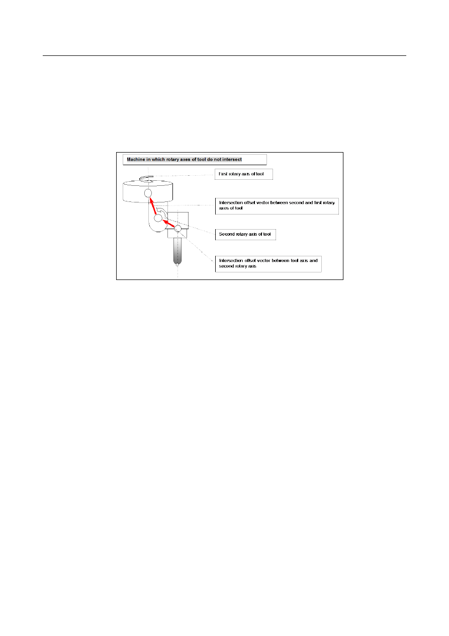
When the rotation axes of the tool do not intersect
Explained below is a mechanism in which the rotation axes of the tool do not intersect each other.
The Fig. 12.16.3.1 (c) is an example of a mechanism in which the first and second rotation axes of the
tool do not intersect.
When both the master and slave are at 0 degrees, a vector from a point on the second rotation axis of the
tool to a point on the first rotation axis of the tool is set as an intersection offset vector between the
second rotation axis of the tool and the first rotation axis of the tool in parameters Nos. 19712 to 19714.
The controlled point can be shifted by setting a shift vector from the point mentioned above in
parameters.
Fig. 12.16.3.1 (c) Mechanism in which the rotation axes of the tool do not intersect
(2) Examples of setting parameters
There are many parameters related to this function.
Therefore, it is recommended that parameters for a target machine be set based on some examples. These
examples are given below.
<1> Example of setting parameters for a composite type machine
In the machine explained in this example, the first axis is X, the second axis is Y, the third axis is Z, the
fourth axis is A, the fifth axis is B, and the sixth axis is C.
Fig. 12.16.3.1 (d) is an example of setting parameters for a composite type machine.
Rotation axis A is a table rotation axis on the X-axis.
Rotation axis B is a tool rotation axis on the Y-axis.