FANUC Series 0i-MODEL F Plus. CONNECTION MANUAL (FUNCTION) - page 279
 

  Index      Manuals     FANUC Series 0i-MODEL F Plus. CONNECTION MANUAL (FUNCTION) B-64693EN-1/01


Search            copyright infringement  


Content      ..     277      278      279      280     ..


FANUC Series 0i-MODEL F Plus. CONNECTION MANUAL (FUNCTION) - page 279


12. PROGRAM COMMAND


B-64693EN-1/01


- 2186 - 

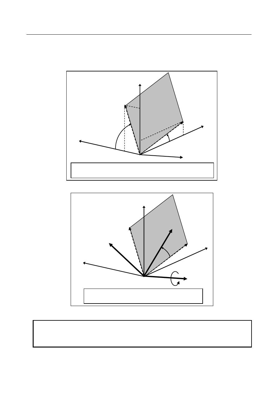
The direction normal to plane P containing vector A and vector B (direction of the outer product of A 

×


B) is defined to be the Z-axis direction of the feature coordinate system. 
Vector  A rotated by 

γ

  about the Z-axis  of the feature coordinate system  is defined to be the X-axis 

direction  of the feature coordinate system. The Y-axis  of the feature coordinate system  is defined 
according to the right-handed system. 


-

α


β


Zc 

Plane P 

By the third command angle 

α

 and second command angle 

β

, the 

Z-axis of the feature coordinate system are determined. 


Fig. 12.16.1.6 (b) Determination of a feature coordinate system (Z axis) 


Yc 

γ


Plane P


Zc 

Xc 

By the third command angle 

γ

, the X-axis and Y-axis of 

the feature coordinate system are 

determined. 


Fig. 12.16.1.6 (c) Determination of a feature coordinate system (X and Y axes) 


NOTE 


When vector A and vector B are considered to be parallel with each other (when 
the angle formed by the two vectors is smaller than 1degree), alarm PS5457, 
"G68.2/G68.3 FORMAT ERROR" is issued. 


B-64693EN-1/01


12. PROGRAM COMMAND


- 2187 - 

12.16.1.7 

Tilted working plane indexing by tool axis direction 

Overview 

By specifying G68.3, a coordinate system (feature coordinate system) where the tool axis direction is the 
+Z-axis direction can be automatically specified. When a feature coordinate system is used, a program for 
cutting a hole or pocket in a plane tilted relative to the workpiece coordinate system can be made simpler. 
This function can automatically generate a feature coordinate system that is normal to the tool direction. 


Fig. 12.16.1.7 (a) Feature coordinate system 

 
When G68.3 is specified  in a block,  the  coordinate  system  for  programming  is changed to a feature 
coordinate system. All commands after the  block  are regarded as commands in the feature coordinate 
system until G69 is specified. 
 

Explanation 

  - 

Feature coordinate system 

By specifying G68.3, a feature coordinate system with the tool axis direction being the +Z-axis direction 
can be created. The  tool  axis  direction  means the tool  axis  direction  based on the rotation  axis  position 
reached by automatic operation or manual operation. 
 

  - 

Origin of a feature coordinate system 

The origin of a feature coordinate system must be specified using an absolute command. 
Even in the incremental command mode, the specified origin is regarded as an absolute position. 
When 1 address or 2 addresses are omitted  in X, Y, or Z, alarm PS5457, "G68.2/G68.3 FORMAT 
ERROR" is issued. 
When the origin of a feature coordinate system is not specified, the position when G68.3 is specified is 
used as the origin. 
 

  - 

Determination of a feature coordinate system 

Determination of a feature coordinate system depends on whether P1 command is present. 
 

(1) When G68.3 block does not include P1 command (G68.3) 

When G68.3 is specified, the tool  axis  direction  vector  (

T

)  represents the +Z direction  (

c

Z

) of the 

feature coordinate system. 

The vector normal to a plane formed by the +Z direction (

c

Z

) of the feature coordinate system and the 

vertical axis direction vector (

P

) (parameter No. 12321) represents the +X direction (

c

X

) of the feature 

coordinate system. 

Expression: 

c

Z

P

c

X

×

=


The vector normal to the +Z direction (

c

Z

) of the feature coordinate system and the +X direction (

c

X

of the feature coordinate system represents the +Y direction (

c

Y

) of the feature coordinate system. 

12. PROGRAM COMMAND


B-64693EN-1/01


- 2188 - 

Expression: 

c

X

c

Z

c

Y

×

=


When R is commanded, a coordinate system rotated by R around Zc axis from the  above-mentioned 
coordinate system is the feature coordinate system. 


Fig. 12.16.1.7 (b) Determination of a feature coordinate system 


When the tool axis direction vector (

T

) is parallel with the vertical axis direction vector (

P

) (parameter 

No. 12321) (when the angle between the vector (

T

) and the vector (

P

) is equal to or less than the value 

of  parameter No.  12322), the feature coordinate system  Xc-Yc-Zc is as indicated below. By specifying 
angular  displacement  R, a feature coordinate system  rotated about the Z-axis  of this coordinate  system 
can be specified. 
 

Table 12.16.1.7 (a)  Feature coordinate system 

Parameter 

No. 12321 

Z-axis of feature coordinate 

system Zc 

X-axis of feature coordinate 

system Xc 

Y-axis of feature coordinate 

system Yc 

+X direction 

+Y direction 

+Z direction 

+Y direction 

+Z direction 

+X direction 

+Z direction 

+X direction 

+Y direction 

 
When 0 is set in parameter No.  12321, the vertical  axis  direction  is the reference  tool  axis  direction 
(parameter No. 19697). 
If a value  other than 0 through 3 is set in parameter No.  12321, the alarm  PS5459, "MACHINE 
PARAMETER INCORRECT" is issued. 
 

NOTE 


Tool axis direction is Z-axis direction of feature coordinate system regardless of 
the reference tool axis direction (parameter No. 19697). 


  - 

Angular displacement R 

Angular displacement R is positive when a rotation is made clockwise viewed in the Z-axis direction of 
the feature coordinate system. The range of angular displacement R is: 0.0degree 

 R 

 360.0degree. 


B-64693EN-1/01


12. PROGRAM COMMAND


- 2189 - 

(2) When G68.3 block includes P1 command (G68.3 P1) 

G68.3  P1 command defines the feature coordinate system corresponding to tool rotation axis position. 
The direction of the feature coordinate system is the direction of reference coordinate system rotated by 
tool rotation axes.   
The reference coordinate system of feature coordinate system (the feature coordinate system that is 
defined when absolute coordinate system of tool rotation axes is  0) is as follows by the parameter 
No.19697 for reference tool axis direction. 
The feature coordinate system defined by "G68.3 P1" command is the coordinate system that the 
reference coordinate system is rotated  by tool rotation axis position and reference angle RA (parameter 
No.19698), RB (parameter No.19699). 


Fig. 12.16.1.7 (c) The reference coordinate system of feature coordinate system (G68.3 P1) 


X,Y direction of 
feature coordinate system 

Z direction of 
feature coordinate system 

12. PROGRAM COMMAND


B-64693EN-1/01


- 2190 - 


Fig. 12.16.1.7 (d) Example that reference tool axis direction is Z direction 


  - 

Machine of table rotation type 

On a machine of table rotation type, the tool direction remains unchanged. So, a feature coordinate system 
based on the reference tool axis direction (parameter No.19697) is set. However, the origin specification 
of the feature coordinate system and angular displacement R about the Z-axis are valid. 


Fig. 12.16.1.7 (e) Machine of table rotation type 


G53.1 / G53.6 command in G68.3 mode 

When G53.1 or G53.6 command is executed  in G68.3 mode, alarm PS5458 “ILLEGAL USE OF 
G53.1/G53.6” occurs. 
 

  - 

Use in combination with tool length compensation 

The G68.3 command can be specified even during tool length compensation. 
 

Workpiece coordinate system X-Y-Z 

Example:  When reference tool axis direction represents +Z-axis direction 

(with parameter No. 19697 set to 3) 

Feature coordinate system 
Xc-Yc-Zc 

Xc 

Yc 

Zc 

Tool rotation axis : C=45deg, B=20deg. 


C


B


Z


Y


X


B


C


Y


X


Z


B


C


Tool rotation axis : C=45deg, B=0deg. 

Z


Y


X


C


C


Z direction of   
Feature coordinate system 

Y direction of   
Feature coordinate system 

X direction of   
Feature coordinate system 

Y direction of   
Feature coordinate system 

Z direction of   
Feature coordinate system 

X direction of   
Feature coordinate system 

B-64693EN-1/01


12. PROGRAM COMMAND


- 2191 - 

  - 

Example of operation 

An example of operation on a machine of tool rotation type is given below. 
The machine configuration is "BC type reference tool axis Z-axis". 


Fig. 12.16.1.7 (f) Example of operation on a machine of tool rotation type 

 
Sample program 1 
O0100 ; 
N1 G55 ; 
N2 G90 G01 X0Y0Z50.0 F1000 ; 
N3 G43 H01 X0 Y0 Z0 ; 
N4 B-45.0 ; 
N5 G68.3 ; 

N6 G69 ; 


12. PROGRAM COMMAND


B-64693EN-1/01


- 2192 - 


Fig. 12.16.1.7 (g) Machine operation with sample program 1 

 
N3 block: Performs tool length compensation in the workpiece coordinate system. 


The tool center point moves to the origin of the workpiece coordinate system. 

N4 block: Tilts the tool. 
N5 block: Sets a feature coordinate system where the tool axis direction is the Z-axis direction   

and the tool center point is placed at the origin. 

N6 block: Cancels the feature coordinate system to return to the workpiece coordinate system. 
 
Sample program 2 
O0100 ; 
N1 G54 G90 G00 B0 C0 ; 
N2 B45.0 ; 
N3 C60.0 ; 
N4 G68.3 P1 X0 Y0 Z0 ; 

B-64693EN-1/01


12. PROGRAM COMMAND


- 2193 - 


Fig. 12.16.1.7 (h) 

 
N2 block: Tilts the tool. (B45 deg) 
N3 block: Tilts the tool. (C60 deg) 
N4 block: The direction of the reference coordinate system of feature coordinate system is the direction 


of workpiece coordinate system because the reference tool axis direction is Z direction. The 


feature coordinate system is the coordinate system that the reference coordinate system is 


rotated by 45 deg. around Y direction and 60 deg. around Z direction. 

XF : The direction that X direction of workpiece coordinate system is rotated by 60 deg. around Z 

direction after by 45 deg. around Y direction of workpiece coordinate system. 

YF : The direction that Y direction of workpiece coordinate system is rotated by 60 deg. round Z 

direction of workpiece coordinate system. 

ZF : The direction that Z direction of workpiece coordinate system is rotated by 60 deg. around Z 

direction after by 45 deg. around Y direction of workpiece coordinate system. 


  - 

Multiple G68.3 

After the tool axis direction is changed in G68.3 mode, by specifying G68.3, a new feature coordinate 
system where the tool axis direction is the +Z-axis direction can be specified. 
 

Z

F


N2 command 

Sample program2 

X

F


Y

F


B45.0 

C60.0 

C60

°


B45

°


C60

°


N3 command 

N4 command 

Feature coordinate system X

F

-Y

F

-Z

F


Workpiece coordinate 

system X-Y-Z 

Workpiece coordinate 

system X-Y-Z 


Content      ..     277      278      279      280     ..