FANUC Series 0i-MODEL F Plus. CONNECTION MANUAL (FUNCTION) - page 278
 

  Index      Manuals     FANUC Series 0i-MODEL F Plus. CONNECTION MANUAL (FUNCTION) B-64693EN-1/01


Search            copyright infringement  


Content      ..     276      277      278      279     ..


FANUC Series 0i-MODEL F Plus. CONNECTION MANUAL (FUNCTION) - page 278


12. PROGRAM COMMAND


B-64693EN-1/01


- 2178 - 


Fig. 12.16.1.1 (a)    Coordinate conversion using an Euler's angle 


  - 

I0 J0 K0 command 

When I0 J0 K0 is specified as an Euler's angle, the  alarm PS5457,  "G68.2/G68.3 FORMAT ERROR" 
usually occurs. When bit 1 (ATW) of parameter No. 13451 is set to 1, the feature coordinate system with 
a tilted angle of 0 degree is used.   
 

12.16.1.2 

General specifications of the tilted working plane indexing 

  - 

Constant surface speed control 

Constant surface speed control is exercised by using as the reference the following axis according to bit 6 
(3CS) of parameter No.11221.  (Refer to the explanation of  "CONSTANT SURFACE SPEED 
CONTROL" for details) 

3CS=0 : the machine axis specified in address P in a G96 block or the machine axis (in the actually 
operating workpiece coordinate system) set in parameter No. 3770. 

3CS=1 : the axis in the feature coordinate system 


  - 

Rapid traverse in a canned cycle for drilling 

By using bit 1 (D3R) of parameter No. 11221, rapid traverse in the drilling direction in a canned cycle for 
drilling during the tilted working plane indexing  mode,  3-dimensional coordinate system conversion 
mode can be selected and the rapid traverse mode for shift operation in fine boring (G76) or back boring 
(G87) for the M system can also be selected. When parameter D3R is set to 0, the cutting feed mode is 
selected. When parameter D3R is set to 1, the rapid traverse  mode is selected. For positioning  to the 
initial level at the start of a canned cycle for drilling, however, the rapid traverse mode is used, regardless 
of the setting of parameter D3R. Rapid traverse override is applied during the rapid traverse mode, and 
cutting feed override is applied during the cutting feed mode. Parameter D3R is also usable to change the 
mode of rapid traverse in the rigid tapping direction. 
 

B-64693EN-1/01


12. PROGRAM COMMAND


- 2179 - 

For acceleration/deceleration after interpolation 
 

When parameter D3R is set to 1 (for the rapid traverse mode), rapid traverse in the drilling direction 
in a canned cycle  for  drilling  during the tilted working plane indexing  mode,  3-dimensional 
coordinate system conversion mode is accelerated/decelerated on each axis independently according 
to the time constants specified in parameter No. 1620 and parameter No. 1621. So, when performing 
positioning of linear interpolation type with parameter D3R set to 1, make the following settings: 


Bit 1 (LRP) of parameter No. 1401=1  Selects positioning of linear interpolation type. 
Bit 4 (PRT) of parameter No. 1603=1  Selects acceleration/deceleration of constant time type. 
Parameter No. 1620  

(Tab) 

Set the same value for all. 

Parameter No. 1621  

(Tab) 

Set the same value for all. 

 
For look-ahead acceleration/deceleration before interpolation 
 

In a canned cycle for drilling, linear rapid traverse in the drilling direction is performed at all times. 

 
Feedrate 
 

When parameter D3R is set to 1 (for the rapid traverse mode), the rapid traverse rate in the drilling 
direction in a canned cycle for drilling during the tilted working plane indexing mode, 3-dimensional 
coordinate system conversion  mode is clamped to a parameter  value  indicated  below if the rapid 
traverse override is 100%. In the rapid traverse override F0 mode, however, the rapid traverse rate is 
clamped to the value of parameter No. 1421 or a parameter value in Table , whichever smaller. 


Table 12.16.1.2 (a) Feedrate for rapid traverse mode 

Parameter No. 5412=0 

Parameter No. 1420 

Parameter No. 5412

Value of parameter No. 1420 or value of parameter No. 5412, whichever smaller 


However, when the external deceleration function is enabled, the feedrate is clamped to a parameter 
value in Table    that is overridden or an external deceleration speed, whichever smaller. 


NOTE 

1  Set a rapid traverse rate for each axis in parameter No. 1420, and set a 

tangential rapid traverse rate in parameter No. 5412. 

2  If rapid traverse of nonlinear interpolation type is performed, the feedrate is 

clamped to the value of parameter No. 1420, regardless of the setting of 
parameter No. 5412. 

3  When the cutting feed mode is selected (parameter D3R = 0), set a tangential 

rapid traverse rate in parameter No. 5412. 


  - 

Workpiece coordinate system selection command during the tilted working 
plane indexing 

By executing the workpiece coordinate system selection command (G54 to G59, G54.1) during the tilted 
working plane indexing  when bit 6 (3TW) of parameter No. 1205 is 1, it is possible to change the 
workpiece coordinate system. In this case, the coordinate system zero point shift of the tilted working 
plane indexing is maintained. 
If an attempt is made to execute the workpiece coordinate system selection command (G54 to G59, 
G54.1) during the tilted working plane indexing when bit 6 (3TW) of parameter No. 1205 is 0, alarm 
PS5462, “ILLEGAL COMMAND (G68.2/G69)” is issued. 

12. PROGRAM COMMAND


B-64693EN-1/01


- 2180 - 


Fig. 12.16.1.2 (a) Workpiece coordinate system selection command during the tilted working plane indexing 


  - 

Minimum command unit of rotation angles 

The minimum command unit of the rotation angles (I, J, K, and R) of the tilted working plane indexing is 
0.001 degree regardless of the increment system. By setting bit 2 (TFR) of parameter No. 11630 to 1, the 
minimum command unit of the rotation angles can be set to 0.00001 degree. 
 

Cutting feedrate clamp 

The cutting feedrate is clamped so that the feedrate of each real axis after the conversion by the tilted 
working plane indexing does not exceed the maximum cutting feedrate (Parameter No.1432 if look-ahead 
acceleration/deceleration before interpolation is enabled and parameter No.1430 otherwise). 
 

Local Coordinate System 

The local coordinate system is available to the feature coordinate system during the tilted working plane 
indexing.   
X,Y,Z commands of the local coordinate system command block defines a local coordinate system that 
the feature coordinate system is translated in X,Y,Z direction. 
Alarm PS5462 occurs when the tilted working plane indexing is specified on the condition that the offset 
of the local coordinate system is not zero,   


Reference position 

Machine coordinate system origin 

(Machine coordinate system) 

(G54:    Workpiece coordinate system) 

IP_ 

(Local coordinate system) 

(Feature coordinate system) 


B-64693EN-1/01


12. PROGRAM COMMAND


- 2181 - 

12.16.1.3 

Tilted working plane indexing based on roll-pitch-yaw 

Overview 

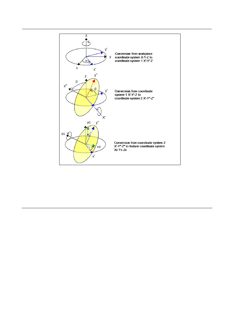
With the tilted working plane indexing, coordinate  system  conversion  by  rotation  about the X-axis, 
Y-axis, and Z-axis of a workpiece coordinate system in this order can be used (roll-pitch-yaw). 
The order of rotary axes can be specified using address Q. 


Fig. 12.16.1.3 (a) Tilted working plane indexing based on roll-pitch-yaw 


Explanation 

Suppose that the coordinate system is rotated about (1) the X-axis, (2) the Y-axis, and (3) the Z-axis in 
this order. 
A "workpiece coordinate system" rotated by angle 

α

 about the X-axis is "coordinate system 1". 

"Coordinate system 1" rotated by angle 

β

 about the Y-axis is "coordinate system 2". "Coordinate system 

2" rotated by angle 

γ

 about the Z-axis then shifted by (X

0

,Y

0

,Z

0

) from the workpiece coordinate system 

origin is a "feature coordinate system". 
 

12. PROGRAM COMMAND


B-64693EN-1/01


- 2182 - 


Fig. 12.16.1.3 (b) Determination of a feature coordinate system 


12.16.1.4 

Tilted working plane indexing based on three points 

Overview 

With the tilted working plane indexing, a tilted working plane can be specified by specifying three points 
in a feature coordinate system. 


Fig. 12.16.1.4 (a) Tilted working plane indexing based on three points 


B-64693EN-1/01


12. PROGRAM COMMAND


- 2183 - 

Explanation 

  - 

Determination of a feature coordinate system 

Three entered points are named P1, P2, and P3 in the order of entry. 
The P1-to-P2 direction is defined as the X-axis of a feature coordinate system. Among the directions that 
are on the plane containing the three points and are normal to the X-axis of the feature coordinate system, 
the direction that makes a smaller angle with the P1-to-P3 vector is defined as the Y-axis of the feature 
coordinate system. The Z-axis of the feature coordinate system is defined according to the right-handed 
system. 


Fig. 12.16.1.4 (b) Determination of a feature coordinate system 


  - 

Origin of the feature coordinate system 

The origin of the feature coordinate system is the first specified point P1. 
By setting an origin shift amount (G68.2 P2 Q0 X_Y_Z_), the origin of the feature coordinate system is 
shifted by (X,Y,Z) from P1. Specify (X,Y,Z) in the feature coordinate system. 
 

  - 

Angular displacement R 

The angular displacement R is positive for clockwise rotation viewed in the Z-axis direction in the feature 
coordinate system. 
 

12. PROGRAM COMMAND


B-64693EN-1/01


- 2184 - 

12.16.1.5 

Tilted working plane indexing based on two vectors 

Overview 

With the tilted working plane indexing, a tilted working plane can be specified by specifying an X-axis 
direction vector and a Z-axis direction vector in the feature coordinate system. 


Fig. 12.16.1.5 (a) Tilted working plane indexing based on two vectors 


Explanation 

  - 

Determination of a feature coordinate system 

The first vector is defined as the X-axis of the feature coordinate system, and the second vector is defined 
as  the  Z-axis  of the feature coordinate system. The Y-axis  of the feature coordinate system  is  defined 
according to the right-handed system. 


Fig. 12.16.1.5 (b) Determination of a feature coordinate system 


B-64693EN-1/01


12. PROGRAM COMMAND


- 2185 - 

  - 

When the first and second vectors are not normal 

When the first vector and second vector are not normal, the orthographical vector from the second vector 
to plane P normal to the first vector is defined as the Z-axis of the feature coordinate system. 


Fig. 12.16.1.5 (c) When the first and second vectors are not normal 


12.16.1.6 

Tilted working plane indexing based on projection angles 

Overview 

With the tilted working plane indexing, a tilted working plane  can be specified  based on projection 
angles. 
A plane determined by vector A and vector B produced by rotating the X-axis vector and Y-axis vector of 
the workpiece coordinate system is defined to be a tilted working plane. 


Fig. 12.16.1.6 (a) Tilted working plane indexing based on projection angles 


Explanation 

  - 

Determination of a feature coordinate system 

The X-axis  direction  vector  of the workpiece  coordinate system  rotated by 

α

  about the Y-axis  of the 

workpiece  coordinate system  is defined as vector  A. The Y-axis  direction  vector  of the workpiece 
coordinate system  rotated by 

β

  about the X-axis  of the workpiece  coordinate system  is defined to be 

vector B. 


Content      ..     276      277      278      279     ..