FANUC Series 0i-MODEL F Plus. CONNECTION MANUAL (FUNCTION) - page 276
 

  Index      Manuals     FANUC Series 0i-MODEL F Plus. CONNECTION MANUAL (FUNCTION) B-64693EN-1/01


Search            copyright infringement  


Content      ..     274      275      276      277     ..


FANUC Series 0i-MODEL F Plus. CONNECTION MANUAL (FUNCTION) - page 276


12. PROGRAM COMMAND


B-64693EN-1/01


- 2162 - 

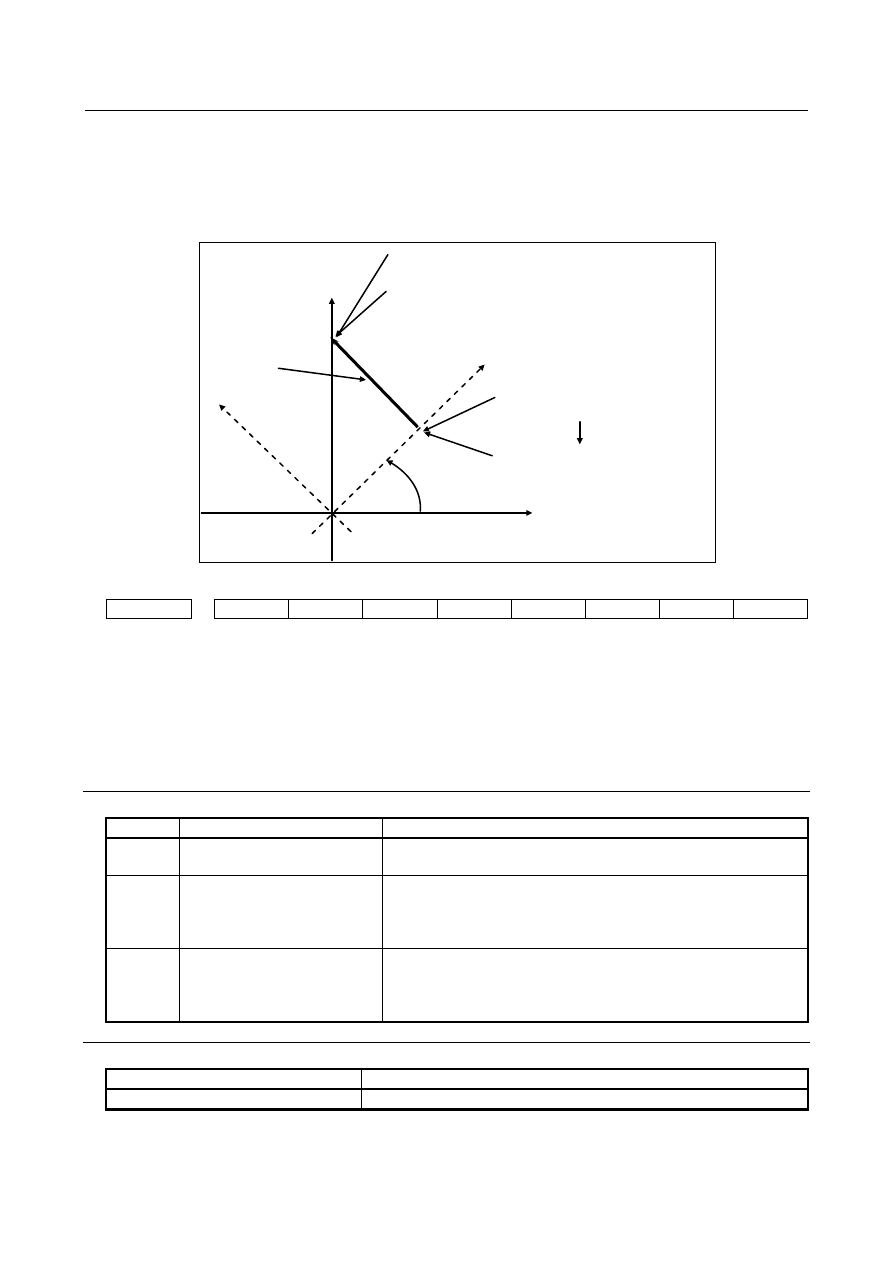
When the bit 5 (AX1) of parameter No. 11600 is set to 1:


The command in (1) converts the coordinates before the coordinate system rotation 
command, (X10,Y10), into the coordinates (X'14.142,Y'0) in the coordinate system 
rotated by 45 degrees (X'Y'). Then, the tool moves to the specified position 
(X'14.142,Y'14.142), i.e., the movement position (X0,Y20). 


Coordinates in the coordinate 
system after rotation 
: X'14.142,Y'0 
 

Coordinates before the coordinate 
system rotation command   
: X10,Y10 
 

45 
degrees 

X' 

Y' 


Specified position 
: X'14.142,Y'14.142 
Movement position 
: X0,Y20 
 

Conversion 

Tool path 


#7 

#6 

#5 

#4 

#3 

#2 

#1 

#0 

11630 


FRD 


[Input type]  Parameter input 


[Data type]  Bit path 


#0  FRD

  The minimum command unit of the rotation angles of coordinate rotation and 

3-dimensional coordinate system conversion is: 
0: 

0.001 degree. 

1: 

0.00001 degree. (1/100,000) 


Alarm and message 

Number 

Message 

Description 

PS0144 

ILLEGAL PLANE SELECTED 

The coordinate rotation plane and arc or tool radius

tool nose radius 

compensation plane must be the same. Modify the program. 

PS0412 

ILLEGAL G CODE 

During coordinate system rotation, the G code for reference position 
return (G27, G28, G29, G30) or coordinate system setting (G52 to 
G59, G92), is specified. Before specifying any of them, cancel the 
coordinate system rotation mode. 

PS0509 

TOOL OFFSET COMMAND IS 
NOT AVAILABLE 

-  Tool offset (for the lathe system) was specified in the thread 

cutting block. 

-  Tool offset was specified (lathe system) in the coordinate system 

rotation mode, or programmable mirror image mode. 


Reference item 

Manual name 

Item name 

OPERATOR’S MANUAL (B-64694EN) 

Coordinate system rotation 


B-64693EN-1/01


12. PROGRAM COMMAND


- 2163 - 

Limitation 

  - 

R-specified arc 

When an R-specified arc is specified after beginning the coordinate system rotation mode, please specify 
the command to the start point by the absolute commands in the previous block. 
 

Specifying during AI high-precision contour control mode or 3-dimensional 
coordinate system conversion mode


Coordinate system rotation can always be specified for the M series and can be specified for the T series 
only when the G code system B or C is used. 
 

  - 

Tool offset 

T


If tool offset by shifting the coordinate system is specified (by setting bit 2 (LWT) of parameter No. 5002 
to 1 or bit 4 (LGT) of parameter No. 5002 to 0) in the coordinate system rotation mode, alarm PS0509, 
“TOOL OFFSET COMMAND IS NOT AVAILABLE”, will occur. 
The same alarm will occur if a tool compensation value is modified by setting bit 6 (EVO) of parameter 
No. 5001. 
 

Caution 

  CAUTION 


Before specifying the G code for reference position return (G27, G28, G29, G30) 
or coordinate system setting (G52 to G59, G92), cancel the coordinate system 
rotation mode. If any of them is specified during coordinate system rotation 
mode, alarm PS0412, “AN UNUSABLE G CODE WAS USED”, will occur.   


12.15 

3-DIMENSIONAL COORDINATE CONVERSION 

Overview 

The coordinate system can be rotated about an arbitrary axis by specifying the center of rotation, direction 
of the axis of rotation, and angular displacement. 
This coordinate conversion function is quite useful for 3-dimensional machining on a diesinking machine. 
By applying this conversion to a program generated for machining on the XY plane, identical machining 
can be executed on the desired plane. 
When rigid tapping is commanded in 3-dimensional coordinate conversion mode, tapping can be done at 
the angle specified by a 3-dimensional coordinate conversion command. (This is called 3-dimensional 
rigid tapping.) 

12. PROGRAM COMMAND


B-64693EN-1/01


- 2164 - 


Three-dimensional 
coordinate 
conversion 


Explanation 

  - 

Rapid traverse in a canned cycle for drilling 

By using bit 1 (D3R) of parameter No. 11221, rapid traverse in the drilling direction in a canned cycle for 
drilling in the tilted working plane indexing mode or 3-dimensional coordinate conversion mode can be 
selected and the rapid traverse mode for shift operation in fine boring (G76) or back boring (G87) for the 
M system can also be selected. When D3R is set to 0, the cutting feed mode is selected; when it is set to 1, 
the rapid traverse mode is selected. For positioning to  the initial level at the start of a canned cycle for 
drilling, however, the rapid traverse mode is used, regardless of whether D3R is set to 0 or 1. Rapid 
traverse override can be applied in the rapid traverse mode, and cutting feed override can be applied in the 
cutting feed mode. D3R can also be used to change the mode of rapid traverse in the rigid tapping 
direction. 
 
For acceleration/deceleration after interpolation 
 

When bit 1 (D3R) of parameter No. 11221 is set to 1 (for the rapid traverse mode), rapid traverse in 
the drilling direction in a canned cycle for drilling in the tilted working plane indexing  mode  or 
3-dimensional coordinate conversion mode is accelerated/decelerated along each axis independently 
according to the time constants specified in parameters Nos. 1620 and 1621. So, when performing 
positioning of linear interpolation type with D3R set to 1, make the following settings: 


Bit 1 of (LRP) of parameter No. 1401=1  Selects positioning of linear interpolation type. 


Bit 1 of (PRT) of parameter No. 1603=1  Selects acceleration/deceleration of constant time type. 


Parameter No. 1620 

Set the same value for all. 


Parameter No. 1621 

Set the same value for all. 

 
For look-ahead acceleration/deceleration before interpolation 
 

In a canned cycle for drilling, linear rapid traverse in the drilling direction is performed at all times. 

 
Feedrate 
 

When bit 1 (D3R) of parameter No. 11221 is set to 1 (for the rapid traverse mode), the rapid traverse 
rate in the drilling direction in a canned cycle for drilling in the tilted working plane indexing mode 
or 3-dimensional coordinate conversion mode is clamped to a parameter value indicated below if the 
rapid traverse override is 100%. In the rapid traverse override F0 mode, however, the rapid traverse 
rate is clamped to the value of parameter No. 1421 or a parameter value listed in Table  12.15  (a), 
whichever smaller. 


B-64693EN-1/01


12. PROGRAM COMMAND


- 2165 - 

Table 12.15 (a) Feedrate in the rapid traverse mode 

Parameter No. 5412=0 

Parameter No. 1420 

Parameter No. 5412

Value of parameter No. 1420 or value of parameter 5412, whichever smaller 


However, when the external deceleration function is enabled, the feedrate is clamped to a parameter 
value listed in Table  12.15  (a)  that is overridden or an external deceleration speed, whichever 
smaller. 


NOTE 

1  Set a rapid traverse rate for each axis in parameter No. 1420 and a tangential 

rapid traverse rate in parameter No. 5412. 

2  If rapid traverse of nonlinear interpolation type is performed, the feedrate is 

clamped to the value of parameter No. 1420, regardless of the setting of 
parameter No. 5412. 

3  When the cutting feed mode is selected (when bit 1 (D3R) of parameter No. 

11221 is set to 0), set a tangential rapid traverse rate in parameter No. 5412. 


  - 

Cutting feedrate clamp 

The cutting feedrate is clamped so that the feedrate of each real axis after the 3-dimensional coordinate 
system conversion does not exceed the maximum cutting feedrate

Parameter No.1432 if look-ahead 

acceleration/deceleration before interpolation is enabled and parameter No.1430 otherwise). 
 

  - 

Interlock signal for each axis direction, interlock signal for each axis, external 
deceleration signal 

When bit 2 (D3IT) of parameter No.11600 is set to 1 and bit 5 (ITM) of parameter No.11223 is set to 1, 
the following signals are enabled for axis of machine coordinate system.   
-  Interlock signal for each axis direction during manual intervention / manual handle interrupt in 

3-dimensional coordinate system conversion mode 

-  Interlock signal for each axis during manual intervention / manual handle interrupt in 3-dimensional 

coordinate system conversion mode 

-  External deceleration signal during manual intervention / manual handle interrupt in 3-dimensional 

coordinate system conversion mode 

- External deceleration signal during 3-dimensional coordinate conversion 
By this setting, all signals of controlled axis type are enabled for axis of machine coordinate system 
during 3-dimensional coordinate conversion. 
 

Table12.15 (b) Relationship between coordinate system of target axis of each signal during 3-dimensional 

coordinate conversion (automatic operation) and parameter setting 

D3IT 

ITM 

Interlock for each axis 

direction 

Interlock for each axis 

External deceleration 

Programming coordinate 

system 

Interlock all X, Y, Z-axis 

Programming coordinate 

system 

Machine coordinate system 

Machine coordinate system 

Programming coordinate 

system 

Machine coordinate system 

Machine coordinate system 

Machine coordinate system 


12. PROGRAM COMMAND


B-64693EN-1/01


- 2166 - 

Table12.15 (c) Relationship between coordinate system of target axis of each signal during manual 

intervention / manual handle interrupt in 3-dimensional coordinate system conversion mode and parameter 

setting 

D3IT 

ITM 

Interlock for each axis 

direction 

Interlock for each axis 

External deceleration 

Programming coordinate 

system 

Programming coordinate 

system 

Programming coordinate 

system 

Programming coordinate 

system 

Programming coordinate 

system 

Programming coordinate 

system 

Machine coordinate system 

Machine coordinate system 

Machine coordinate system 


Reset 

If a reset occurs during 3-dimensional coordinate system conversion mode, the mode is canceled and the 
continuous-state G code is changed to G69. Bit 2 (D3R) of parameter No. 5400 determines whether just 
the G69 code is used to cancel the 3-dimensional coordinate system conversion mode (G68). When this 
setting is selected, a CNC reset by a reset operation or by an input signal from the PMC will not cancel 
the 3-dimensional coordinate system conversion mode. 
 

System variables of skip positions 

System variable number and coordinate system of skip are as Table. The coordinate system of #100151- 
and #151001- changes according to bit 5 (LV3) of parameter No.5400. 
 

Table12.15 (d) Parameter LV3 and coordinate system of skip positions 

System variable 

number 

Coordinate system of skip positions 

Parameter LV3=0 

Parameter LV3=1 

#100151 - 

Workpiece coordinate system 

Program coordinate system 

#151001 - 

Program coordinate system 

Workpiece coordinate system 

#151101 - 

Machine coordinate system 


Program restart 

If the block subject to a restart is in 3-dimensional coordinate conversion mode G68 (machining center 
system)/G68.1 (lathe system), it is possible to select whether the movement of the axes to the restart 
position should be in the program coordinate system or the workpiece coordinate system, by using bit 1 
(3DD) of parameter No.7301. If parameter bit 3DD is 0, the axes move to the restart position one at a 
time, as seen from the program coordinate system, and if it is 1, they move to the restart position one at a 
time, as seen from the workpiece coordinate system. 
The "DESTINATION" and "DISTANCE TO GO" displays follow the setting of 3DD. 
The "ABSOLUTE" display follows the bit 6 (DAK) of parameter No.3106. 
 

3-dimensional coordinate system conversion during tool length compensation 

By setting bit 3 (TLC) of parameter No. 11221 to 1, 3-dimensional coordinate system conversion can be 
used during tool length compensation. In this case, the tool length compensation vector is converted to the 
program coordinate system subject to 3-dimensional coordinate system conversion. This makes 
machining possible while keeping the tool direction to the Z-axis direction of the workpiece coordinate 
system. 
Tool length compensation and 3-dimensional coordinate system conversion must be nested inside each 
other. 

B-64693EN-1/01


12. PROGRAM COMMAND


- 2167 - 

(Example) 


- Constant surface speed control 

Constant surface speed control is exercised by using as the reference the following axis according to bit 6 
(3CS) of parameter No.11221. (Refer to the explanation of “CONSTANT SURFACE SPEED 
CONTROL" for details) 

3CS=0 : the machine axis specified in address P in a G96 block or the machine axis (in the actually


operating workpiece coordinate system) set in parameter No.3770. 

3CS=1 : the axis in the feature coordinate system 


- Angular displacement R 

A positive angular displacement R indicates a clockwise rotation along the axis of rotation. Specify 
angular displacement R in 0.001 degrees within the range of -360000 to 360000. 
To specify angular displacement R in 0.00001 degrees (one hundred-thousandth), set bit 0 (FRD) of 
parameter No.11630 to 1. In this case, angular displacement R is specified within the range of -36000000 
to 36000000.


Limitation 

  - 

Manual reference position return 

An attempt to make a manual reference position return during the 3-dimensional coordinate conversion 
mode results in alarm PS5324,  “REFERENCE RETURN INCOMPLETE”,  being issued. Before 
attempting to make a manual reference position return, cancel the 3-dimensional coordinate conversion 
mode

.


Positioning by optimum accelerations 

The function for positioning by optimum accelerations is disabled during the 3-dimensional coordinate 
system conversion mode. 
 

T


Relationship between 3-dimensional coordinate system conversion and tool 
offset 

When using a tool offset command, nest the tool offset command within the 3-dimensional coordinate 
system conversion mode. 
(Example) 

N10 G43 H1 X_ Y_ Z_ ; 


N20 G68 X0 Y0 Z0 I0.0 J1.0 K0.0 R-30.0 ; 


G69 ; 


G49 X_ Y_ Z_ ;


Workpiece coordinate 
system 

X


Z’ 

X’ 

Program coordinate 
system 

N10 

N20 

Tool length 
compensation vector 

12. PROGRAM COMMAND


B-64693EN-1/01


- 2168 - 

G68.1 X100.0 Y100.0 Z100.0 I0.0 J0.0 K1.0 R45.0 ; 
  : 
T0101; 
  : 
T0100; 
  : 
G69.1 ; 

When tool geometry and wear compensation with coordinate shift is enabled and it is not canceled by 
reset, if tool geometry and wear compensation is executed in 3-dimensional coordinate system conversion 
mode, 3-dimensional coordinate system conversion is not canceled by reset. (Even if it is a setting that 
3-dimensional coordinate system conversion is canceled by reset (parameter D3R(No.5400#2)=0), it is 
not canceled.) 


PMC axis control 

If a command related to 3-dimensional coordinate conversion is specified during PMC axis control, the 
alarm PS5131 is issued. 
 

Signal 

3-dimensional coordinate system conversion manual interruption switch signal 

M3R<Gn031.3> 

  [Classification]  Input signal 
 

[Function]  Specifies  whether  to apply 3-dimensional  coordinate system  conversion  to a manual 

operation  (manual  continuous feed, manual  incremental feed, or manual  handle feed) in 
the 3-dimensional coordinate conversion mode. 


[Operation]  When this signal  is set to 0, 3-dimensional  coordinate system  conversion is not applied 

(the workpiece coordinate system is used). 
When this signal is set to 1, 3-dimensional coordinate system conversion is applied (the 
program coordinate system is used). 


3-dimensional coordinate conversion mode signal D3ROT<Fn062.6> 

  [Classification]  Output signal 
 

[Function]  Posts whether the 3-dimensional coordinate conversion mode is set. 


[Output cond.]  When this signal is set to 1, the 3-dimensional coordinate conversion mode is set. 


Signal address 


#7 

#6 

#5 

#4 

#3 

#2 

#1 

#0 

Gn031 


M3R 


#7 

#6 

#5 

#4 

#3 

#2 

#1 

#0 

Fn062 


D3ROT 


Parameter 

  - 

Setting relative position and absolute position 


#7 

#6 

#5 

#4 

#3 

#2 

#1 

#0 

3104 


DAC 


DAC 

DAL 


DRL 


[Input type]  Parameter input 


[Data type]  Bit path 


#4  DRL

  Relative position 

0: 

The actual position displayed takes into account tool length offset. 

1: 

The programmed position displayed does not take into account tool length offset. 

B-64693EN-1/01


12. PROGRAM COMMAND


- 2169 - 


#6  DAL

  Absolute position 

0: 

The actual position displayed takes into account tool length offset. 

1: 

The programmed position displayed does not take into account tool length offset. 


NOTE 


In lathe systems, whether to exclude a tool offset when displaying 
the absolute position is determined by the setting of bit 1 (DAP) of 
parameter No. 3129. 


#7  DAC

  When an absolute position are displayed: 

0: 

Values not excluding the amount of travel based on cutter compensation and tool 
nose radius compensation are displayed. 

1: 

Values excluding the amount of travel based on cutter compensation and tool nose 
radius compensation (programmed positions) are displayed. 


NOTE 


When the parameter DAC is set to 1, in a command such as circle 
interpolation where the cutter compensation vector is changed 
constantly, an absolute position is not correctly displayed during its 
interpolation except its start point and its end point. 


  - 

Setting absolute coordinates in the 3-dimensional coordinate conversion 
mode 


#7 

#6 

#5 

#4 

#3 

#2 

#1 

#0 

3106 


DAK 


[Input type]  Setting input 


[Data type]  Bit 


#6  DAK

  Specifies whether to display coordinates in the program coordinate system or workpiece 

coordinate system as absolute coordinates when the 3-dimensional coordinate conversion 
mode or the tilted working plane indexing mode is set. 
0: 

Display coordinates in the program coordinate system. 

1: 

Display coordinates in the workpiece coordinate system. 


#7 

#6 

#5 

#4 

#3 

#2 

#1 

#0 

5007 


3OF 

3OC 


[Input type]  Parameter input 


[Data type]  Bit path 


#6  3OC

  If tool length compensation is not cancelled before 3-dimensional coordinate conversion 

is specified, an alarm is: 
0: 

Not raised. 

1: 

Raised. (Alarm (PS0049) “ILLEGAL COMMAND(G68,G69)”) 


#7  3OF

  If 3-dimensional coordinate conversion is not nested with a command for tool length 

compensation, or if 3-dimensional coordinate conversion is specified during tool length 
compensation and another command for tool length compensation is specified: 
0: 

No alarm is issued. 

1: 

The alarm (PS0049) “ILLEGAL COMMAND(G68,G69)” is issued. 


Content      ..     274      275      276      277     ..