FANUC Series 0i-MODEL F Plus. CONNECTION MANUAL (FUNCTION) - page 282
 

  Index      Manuals     FANUC Series 0i-MODEL F Plus. CONNECTION MANUAL (FUNCTION) B-64693EN-1/01


Search            copyright infringement  


Content      ..     280      281      282      283     ..


FANUC Series 0i-MODEL F Plus. CONNECTION MANUAL (FUNCTION) - page 282


12. PROGRAM COMMAND


B-64693EN-1/01


- 2210 - 


Z’ 

Y’ 

Workpiece 
coordinate system 

1st feature 
coordinate system 

Tool length vector 

Tool center point 

Control point 

Z’’ 

Y’’ 

2nd feature coordinate system 

Table 


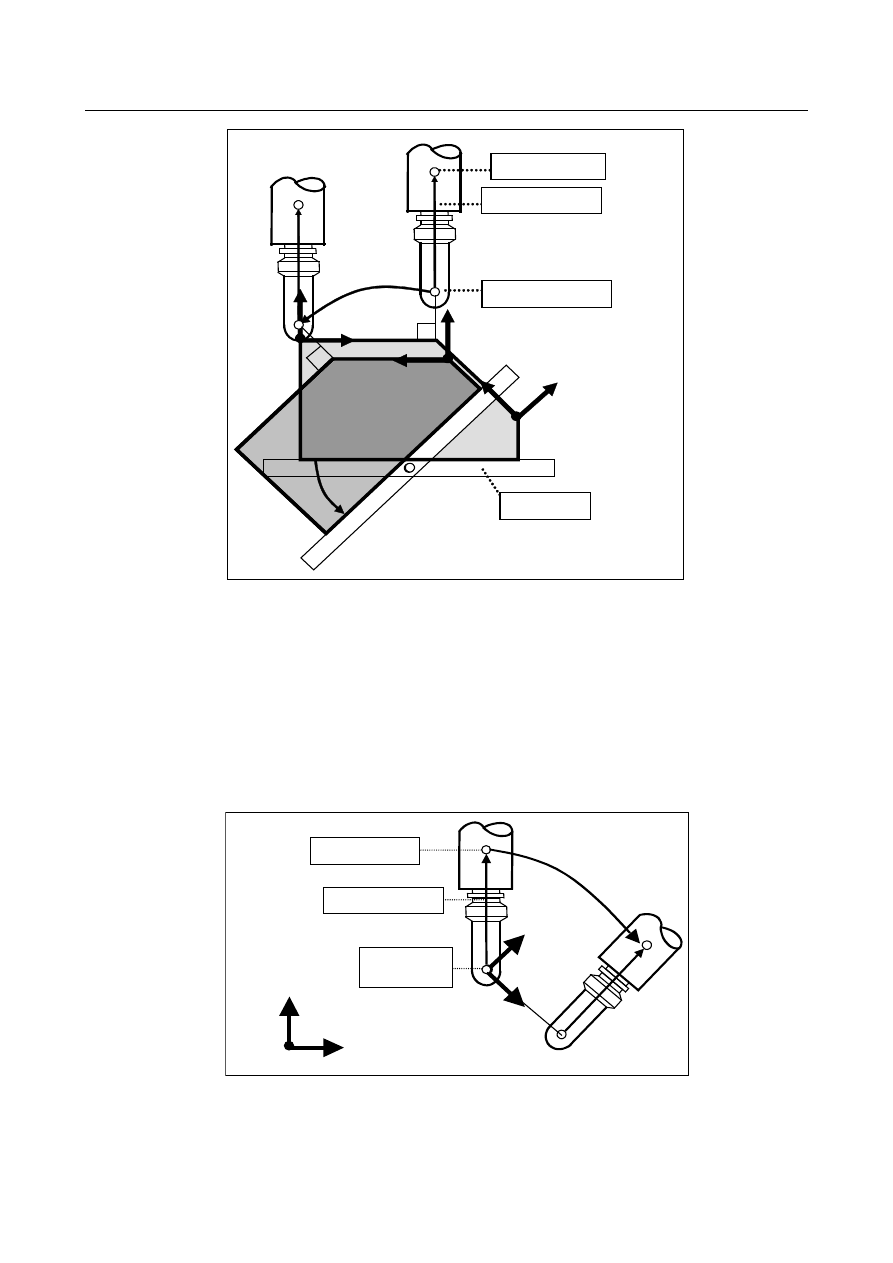
Fig. 12.16.3.2 (b) Operation of tool center point retention type tool axis direction control   

(table rotation type) 

 
Fig. 12.16.3.2 (c) and Fig. 12.16.3.2 (f) show tool center point retention type tool axis direction control 
specified  with end point of tool center point. Tool center point moves on the feature coordinate system 
fixed on the workpiece. 
 
O0012(TCP-HOLD-TYPE-TOOL_ROT) 
G00 B0 C0 
G5.1 Q1 
G68.2 X0 Y0 Z0 I90.0 J45.0 K-90.0 
G53.6 H1 X100.0 Y0 Z0 (G53.6 D1 X100.0 Y0 Z0 for the T series) 


Zf 

Xf 

Z


Control point 

Tool length vector 

Tool center 
point 

Workpiece   
coordinate   
system 

Feature 
coordinate   
system 


Fig. 12.16.3.2 (c) Operation of tool center point retention type tool axis direction control specified with end 

point of tool center point (tool rotation type) 

 
O0022(TCP-HOLD-TYPE-TABLE_ROT) 
G00 B0 C0 

B-64693EN-1/01


12. PROGRAM COMMAND


- 2211 - 

G5.1 Q1 
G68.2 X0 Y0 Z0 I90.0 J45.0 K-90.0 
G53.6 H1 X0 Y0 Z0 (G53.6 D1 X0 Y0 Z0 for the T series) 


Xf 

Zf 

Zf 

Xf 

Table 

1st feature 
coordinate system 

2nd feature   
coordinate   
system 


Fig. 12.16.3.2 (d) Operation of tool center point retention type tool axis direction control specified with end 

point of tool center point (table rotation type) 


Rotation center compensation with the tool center point retention type 

In tool center point retention type tool axis direction control, the rotation center can be shifted from the 
tool center point by specifying R. 
Fig. 12.16.3.2 (e) and Fig. 12.16.3.2 (f) show cases in which the rotation center is shifted by specifying 
the distance from the tool center point to the workpiece with R. 
By specifying this, the tool moves so that it is perpendicular to the titled plane while retaining the rotation 
center on the workpiece. 
This function can be used by specifying G53.6 and specifying a tool length offset number with H (D for 
the T series) and specifying the distance from the tool center point to the rotation center with R. 
 
O0003(CENTER-OF-ROTATION-HOLD-TYPE) 
G00 B0 C0 
G5.1 Q1 
G68.2 X0 Y0 Z0 I90.0 J45.0 K0 
G53.6 H1 R200.0 (G53.6 D1 R200.0 for the T series) 
 

12. PROGRAM COMMAND


B-64693EN-1/01


- 2212 - 


Control point 

Tool length vector 

Tool center point 

Rotation center 

Z’ 

Y’ 

Workpiece 
coordinate system 

Feature coordinate 
system 

r:    Distance from the tool center point to the rotation center 


Fig. 12.16.3.2 (e) Operation of rotation center compensation with tool center point retention type tool axis 

direction control (tool rotation type) 


Rotation 
center 

Z’ 

Y’ 

Workpiece 
coordinate 
system 

1st feature 
coordinate system 

r:    Distance from the tool center point to the rotation center 

Tool length vector 

Tool center point 

Control point 

Z’’ 

2nd feature coordinate system 

Y’’ 

Table 


Fig. 12.16.3.2 (f) Operation of rotation center compensation with tool center point retention type tool axis 

direction control (table rotation type) 


B-64693EN-1/01


12. PROGRAM COMMAND


- 2213 - 

12.16.4 

Tilted Working Plane Indexing in Tool Length Compensation 

Overview 

In tool length compensation (G43), G68.2/G68.4 (tilted working plane indexing) and G53.1 (tool axis 
direction control)/G53.6 (tool center point retention type tool axis direction control) can be specified. 
Accordingly, the G68.2/G68.4 and G53.1/G53.6 commands can be used without canceling tool length 
compensation. 
 

Explanation 

  - 

G68.2/G68.4 command in tool length compensation 

The G68.2/G68.4 command can be executed in tool length compensation. 
Absolute coordinates after the G68.2/G68.4 command are based on the position of the tool center point on 
the feature coordinate system. 
When the tilted working plane indexing is executed with the tool or table tilted on the rotation axis, 
absolute coordinates are based on the position of the tool center point with the position of the rotation 
axis considered. 
Accordingly, machining is allowed even when the tool axis direction is not the Z-axis direction on the 
feature coordinate system. 
 

Example of operation 1 

N10 G69 ; 
N20 G54 

G43

 H1 X0 Y0 Z0 ; 

N30 

G68.2

 X_ Y_ Z_ I90. 0J-30.0 K-90.0 ; (rotation by -30 degrees about the Y-axis) 

N40 X100.0 Y0 Z0 ; 


G54 

Z

F


X

F


Feature coordinate 

system 

N30 

N20 

N40 


Fig. 12.16.4 (a) Example of operation 1 

 
Example of operation 2 

N10 G69 ; 
N20 G54 

G43

 H1 X0 Y0 Z0 B0 ; 

N30 B20.0 ; 
N40 

G68.2

 X_ Y_ Z_ I90.0 J-30.0 K-90.0 ; (rotation by -30 degrees about the Y-axis) 

N50 X100.0 Y0 Z0 ; 
 

12. PROGRAM COMMAND


B-64693EN-1/01


- 2214 - 


G54 

Z

F


X

F


N20 

N50 

N30 

Feature coordinate 

system 

N40 


Fig. 12.16.4 (b) Example of operation 2 (tool rotation type) 


G54 

N20 

Z

F


X

F


N30 

G54 

N20 

Z

F


X

F


N50 

Specify the tilted 
working plane in 
the B0 state in 
N40. 

The feature coordinate system specified in N40 moves 
according to the movement about the table rotation axis. 

Feature coordinate 

system 

N40 


Fig. 12.16.4 (c) Example of operation 2 (table rotation type) 

 
Example of operation 3 

N30 

G43

 X0 Y0 Z0 B20.0 ; 

N40 

G68.2

 X_ Y_ Z_ I90.0 J-30.0 K-90.0 ; (rotation by -30 degrees about the Y-axis) 

N50 X100.0 Y0 Z0 ; 
N60 B-20.0 
N70 

G68.4

 X_ Y_ Z_ I90.0 J40.0 K-90.0 ;

incremental multiple command: rotation by 40 degrees about 

the Y-axis


N80 X100.0 Y0 Z0 ; 
 

B-64693EN-1/01


12. PROGRAM COMMAND


- 2215 - 


Z

F1 

X

F1 

N80 

N50 

N60 

Z

F1 

X

F1 

Feature coordinate 

system 

N40 

Feature coordinate 

system 

N70 


Fig. 12.16.4 (d) Example of operation 3 (tool rotation type) 


N60 

N80 

Z

F1


X

F1


N50 

Specify the tilted 

working plane in the 

B20 state in N70.


The feature coordinate system specified in N70 moves 
according to the movement about the table rotation axis.


Z

F1


X

F1


Z

F2


X

F2


Z

F2


X

F2


Feature coordinate 

system 

N70 

Feature coordinate 

system 

N40 


Fig. 12.16.4 (e) Example of operation 3 (table rotation type) 


G53.1 command in tool length compensation 

The G53.1 command can be executed in tool length compensation. 
G53.1 operation in tool length compensation is performed in the same way as in the tool length 
compensation cancel mode. 
Absolute coordinates after the G53.1 command are based on the position of the tool center point on the 
feature coordinate system after the G53.1 command is specified. 
 

12. PROGRAM COMMAND


B-64693EN-1/01


- 2216 - 

Example of operation 4 

N10 G54 

G43

 H1 X_ Y_ Z_ ; 

N20 

G68.2

 X_ Y_ Z_ I90.0 J-30.0 K-90.0 ; (rotation by -30 degrees about the Y-axis) 

N30 

G53.1

 ; 

N40 X100.0 Y0 Z0 ; 


G54 

Z

F


X

F


N10 

N40 

N30 

Feature coordinate 

system 

N20 


Fig. 12.16.4 (f) Example of operation 4 (tool rotation type) 


G54 

N10 

Z

F


X

F


N30 

G54 

Z

F


X

F


N40 

Feature coordinate 

system 

N20 

Second feature 

coordinate system 

N30 


Fig. 12.16.4 (g) Example of operation 4 (table rotation type) 


G53.6 command in tool length compensation 

The G53.6 command can be executed in tool length compensation. 
G53.6  operation in tool length compensation is performed in the same way as in the tool length 
compensation cancel mode. 
 

G69 command in tool length compensation 

The G69 command can be executed in tool length compensation. 
After G69 operation in tool length compensation, the tool length compensation vector represents the Z 
direction of the workpiece coordinate system regardless of the position of the rotation axis. 

B-64693EN-1/01


12. PROGRAM COMMAND


- 2217 - 


Parameter 


#7 

#6 

#5 

#4 

#3 

#2 

#1 

#0 

1205 


3TW 


[Input type]  Parameter input 


[Data type]  Bit path 


#6  3TW

  When workpiece coordinate system selection is specified with G code in tilted working 

plane indexing mode: 
0: 

The alarm PS5462, "ILLEGAL COMMAND (G68.2/G69)" is issued. 

1: 

Workpiece coordinate system selection is executed. 


  CAUTION 


When this parameter is 1, only G54 to G59 or G54.1 can be 
specified. Specifying G52 or G92 causes alarm PS5462. Specifying 
G54 to G59 or G54.1 suppresses buffering. 


Program example 
G90 G17 
G54 
G68.2 X_Y_Z_ I_ J_ K_   
G53.1 
G43H_ 
G55 X_Y_Z_ 
G56 X_Y_Z_ 
G57 X_Y_Z_ 
G49 
G69


Machine 
zero point 

X_Y_Z_: Coordinate system zero point shift amount 

G54 


Coordinate 

system zero 

point shift 

amount 

Feature coordinate 

system (G68.2) 

G55 


Coordinate 

system zero 

point shift 

amount 


G56 


Coordinate 

system zero 

point shift 

amount 


G57 


Coordinate 

system zero 

point shift 

amount 


Feature coordinate 

system (G68.2) 

Feature coordinate 

system (G68.2) 

Feature coordinate 

system (G68.2) 


#7 

#6 

#5 

#4 

#3 

#2 

#1 

#0 

3106 


DAK 


[Input type]  Setting input 


[Data type]  Bit 


#6  DAK

  Specifies whether to display coordinates in the program coordinate system or workpiece 

coordinate system as absolute coordinates when the 3-dimensional coordinate conversion 
mode, the tilted working plane indexing mode is set. 
0: 

Display coordinates in the program coordinate system. 


Content      ..     280      281      282      283     ..