FANUC Series 0i-MODEL F Plus. CONNECTION MANUAL (FUNCTION) - page 253
 

  Index      Manuals     FANUC Series 0i-MODEL F Plus. CONNECTION MANUAL (FUNCTION) B-64693EN-1/01


Search            copyright infringement  


Content      ..     251      252      253      254     ..


FANUC Series 0i-MODEL F Plus. CONNECTION MANUAL (FUNCTION) - page 253


11. TOOL FUNCTIONS


B-64693EN-1/01


- 1978 - 


Pot No. 

    (Row-Column) 

Tool management 

No. 

Pot No. 

    (Row-Column) 

Tool management 

No. 

Pot No. 

    (Row-Column) 

Tool management 

No. 

1(01-01) 

11(03-01) 

21(05-01) 

2(01-02) 

12(03-02) 

22(05-02) 

3(01-03) 

13(03-03) 

23(05-03) 

4(01-04) 

14(03-04) 

24(05-04) 

5(01-05) 

15(03-05) 

25(05-05) 

6(02-01) 

16(04-01) 


7(02-02) 

17(04-02) 


8(02-03) 

18(04-03) 


9(02-04) 

19(04-04) 


10(02-05) 

20(04-05) 


Cartridge management table 

Oversize tool 

Pots occupied by oversize tool


Tool figure No.  Left direction  Right direction


Upper direction 

Lower direction


Figure 

Omitted 

19 

20 


Tool figure setting screen 


NOTE 

1  Even if a tool figure number is set in the tool management data, the tool is 

regarded as a normal tool when the tool information #2 is set to 0. 

2  If all data items corresponding to a tool figure number are set to 0 (0 for the 

upper, lower, left, and right directions), the tool is regarded as a normal tool even 
when the tool information #2 is set to 1. 


  - 

Tool figure setting screen 

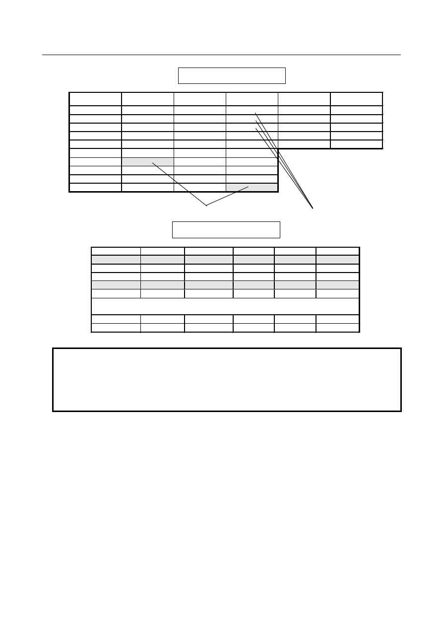
The area  occupied by a tool depends on whether the tool is stored in a cartridge of matrix type or a 
cartridge of chain type. A tool stored in a cartridge of matrix type occupies pots in the upper, lower, left, 
and right directions. A tool stored in a cartridge of  chain type occupies pots only in the left and right 
directions. 
 

  - 

Cartridge of matrix type 

The area occupied by a tool stored in a cartridge of matrix type is described below. 
Set left, right, upper, and lower pots occupied relative to a reference pot in steps of 0.5 pot. The maximum 
specifiable value is 4 (for 2 pots). (See Fig. 11.3.3 (a).) 
As shown in Fig.  11.3.3  (b), the pots located in the slant directions relative to a reference pot are 
automatically assumed to be occupied areas so that the occupied areas form a rectangle. However, if the 
same value, 3 or a greater value, is set for the left, right, upper, and lower directions, and figure B is 
selected, the four corners of the square can be excluded from the occupied areas as shown in Fig. 11.3.3 
(c). When a tool has a circular figure, the tool can be stored efficiently in pots if figure B is selected. 
 

B-64693EN-1/01


11. TOOL FUNCTIONS


- 1979 - 

Table 11.3.3 (a) Tool figure data 

Tool pattern No. 

Left direction


Right direction 

Upper direction 

Lower direction 

Figure 

Omitted 

19 

20 


Fig. 11.3.3 (a) Tool figure data setting 


Fig. 11.3.3 (b) For tool figure pattern number 1 in Table 11.3.3 (a) 


11. TOOL FUNCTIONS


B-64693EN-1/01


- 1980 - 


Fig. 11.3.3 (c) Occupied area for figure B 


  - 

Cartridge of chain type 

The area occupied by a tool stored in a cartridge of chain type is described below. 
As with the matrix type, input data on the tool figure setting screen. In this case, set pots to be occupied 
only in the left and right directions. The specification of pots in the upper and lower directions and a 
figure are ignored. 


Fig. 11.3.3 (d) For tool figure data 19 


NOTE 

1  Tool figure data cannot be modified if the tool for which the tool figure number is 

set is registered in the cartridge. 

2  When changing the tool figure number of a tool registered in the cartridge, 

ensure that the figure after the change does not interfere with other tools. If 
interference with other tools occurs, a warning is issued to disable an attempt to 
change the tool figure number. 


B-64693EN-1/01


11. TOOL FUNCTIONS


- 1981 - 

  - 

System variables 

The following tool management data of the tool being used as a spindle after a tool change by M06 and 
the tool to be used next which is specified by a T code can be read through custom macro variables. The 
custom macro variable is a read-only variable. 

Number 

Item 

#8415 

Tool figure number (A) 


  - 

Tool management extension function 

Customization of tool management data display 


In customization of tool management data display with the tool management extension function, tool 
figure number display can be customized. 

Item 

Display width 

12 

Tool figure number (A) 


Protection of diverse tool information with KEY signals 


With the tool management data protection signal, TKEY1 <G330.1>, the input of tool shape 
numbers using MDI keys is prohibited. 


Parameter 


#7 

#6 

#5 

#4 

#3 

#2 

#1 

#0 

13240 


MT4 

MT3 

MT2 

MT1 


[Input type]  Parameter input 


[Data type]  Bit 


NOTE 


When at least one of these parameters is set, the power must be 
turned off before operation is continued. 


#0  MT1

  The first cartridge is of the: 

0: 

Chain type. 

1: 

Matrix type. 

When this parameter is set to 1, parameter No. 13222 is invalid. 


#1  MT2

  The second cartridge is of the: 

0: 

Chain type. 

1: 

Matrix type. 

When this parameter is set to 1, parameter No. 13227 is invalid. 


#2  MT3

  The third cartridge is of the: 

0: 

Chain type. 

1: 

Matrix type. 

When this parameter is set to 1, parameter No. 13232 is invalid. 


#3  MT4

  The fourth cartridge is of the: 

0: 

Chain type. 

1: 

Matrix type. 

When this parameter is set to 1, parameter No. 13237 is invalid. 
 

11. TOOL FUNCTIONS


B-64693EN-1/01


- 1982 - 

13241 


Number of rows of the first cartridge (when the cartridge is of the matrix type) 


NOTE 


When this parameter is set, the power must be turned off before 
operation is continued. 


[Input type]  Parameter input 


[Data type]  Word 

[Valid data range]  0 to 1000 

When the first cartridge is of the matrix type (bit 0 (MT1) of parameter No. 13240 is set 
to 1), set the number of rows in the pot in this parameter. The setting must satisfy the 
following condition, however: The sum total of the value obtained by (setting  of 
parameter No. 13241) 

×

 (setting of parameter No. 13242) and the number of pots of other 

cartridges should not exceed 64 (1000 at maximum). If this condition is not satisfied or 
this parameter is set to 0, the first cartridge is invalid. 
 

13242 


Number of columns of the first cartridge (when the cartridge is of the matrix type) 


NOTE 


When this parameter is set, the power must be turned off before 
operation is continued. 


[Input type]  Parameter input 


[Data type]  Word 

[Valid data range]  0 to 1000 

When the first cartridge is of the matrix type (bit 0 (MT1) of parameter No. 13240 is set 
to 1), set the number of columns in the pot in this parameter. The setting must satisfy the 
following condition, however: The sum total of the value obtained by (setting of 
parameter No. 13241) 

×

 (setting of parameter No. 13242) and the number of pots of other 

cartridges should not exceed 64 (1000 at maximum). If this condition is not satisfied or 
this parameter is set to 0, the first cartridge is invalid. 
 

13243 


Number of rows of the second cartridge (when the cartridge is of the matrix type) 


NOTE 


When this parameter is set, the power must be turned off before 
operation is continued. 


[Input type]  Parameter input 


[Data type]  Word 

[Valid data range]  0 to 1000 

When the second cartridge is of the matrix type (bit 1 (MT2) of parameter No. 13240 is 
set to 1), set the number of rows in the pot in this parameter. The setting must satisfy the 
following condition, however: The sum total of the value obtained by (setting of 
parameter No. 13243) 

×

 (setting of parameter No. 13244) and the number of pots of other 

cartridges should not exceed 64 (1000 at maximum). If this condition is not satisfied or 
this parameter is set to 0, the second cartridge is invalid. 
 

B-64693EN-1/01


11. TOOL FUNCTIONS


- 1983 - 

13244 


Number of columns of the second cartridge (when the cartridge is of the matrix type) 


NOTE 


When this parameter is set, the power must be turned off before 
operation is continued. 


[Input type]  Parameter input 


[Data type]  Word 

[Valid data range]  0 to 1000 

When the second cartridge is of the matrix type (bit 1 (MT2) of parameter No. 13240 is 
set to 1), set the number of columns in the pot in this parameter. The setting must satisfy 
the following condition, however: The sum total of the value obtained by (setting of 
parameter No. 13243) 

×

 (setting of parameter No. 13244) and the number of pots of other 

cartridges should not exceed 64 (1000 at maximum). If this condition is not satisfied or 
this parameter is set to 0, the second cartridge is invalid. 
 

13245 


Number of rows of the third cartridge (when the cartridge is of the matrix type) 


NOTE 


When this parameter is set, the power must be turned off before 
operation is continued. 


[Input type]  Parameter input 


[Data type]  Word 

[Valid data range]  0 to 1000 

When the third cartridge is of the matrix type (bit 2 (MT3) of parameter No. 13240 is set 
to 1), set the number of rows in the pot in this parameter. The setting must satisfy the 
following condition, however: The sum total of the value obtained by (setting  of 
parameter No. 13245) 

×

 (setting of parameter No. 13246) and the number of pots of other 

cartridges should not exceed 64 (1000 at maximum). If this condition is not satisfied or 
this parameter is set to 0, the third cartridge is invalid. 
 

13246 


Number of columns of the third cartridge (when the cartridge is of the matrix type) 


NOTE 


When this parameter is set, the power must be turned off before 
operation is continued. 


[Input type]  Parameter input 


[Data type]  Word 

[Valid data range]  0 to 1000 

When the third cartridge is of the matrix type (bit 2 (MT3) of parameter No. 13240 is set 
to 1), set the number of columns in the pot in this parameter. The setting must satisfy the 
following condition, however: The sum total of the value obtained by (setting of 
parameter No. 13245) 

×

 (setting of parameter No. 13246) and the number of pots of other 

cartridges should not exceed 64 (1000 at maximum). If this condition is not satisfied or 
this parameter is set to 0, the third cartridge is invalid. 
 

11. TOOL FUNCTIONS


B-64693EN-1/01


- 1984 - 

13247 


Number of rows of the fourth cartridge (when the cartridge is of the matrix type) 


NOTE 


When this parameter is set, the power must be turned off before 
operation is continued. 


[Input type]  Parameter input 


[Data type]  Word 

[Valid data range]  0 to 1000 

When the fourth cartridge is of the matrix type (bit 3 (MT4) of parameter No. 13240 is set 
to 1), set the number of rows in the pot in this parameter. The setting must satisfy the 
following condition, however: The sum total of the value obtained by (setting of 
parameter No. 13247) 

×

 (setting of parameter No. 13248) and the number of pots of other 

cartridges should not exceed 64 (1000 at maximum). If this condition is not satisfied or 
this parameter is set to 0, the fourth cartridge is invalid. 
 

13248 


Number of columns of the fourth cartridge (when the cartridge is of the matrix type) 


NOTE 


When this parameter is set, the power must be turned off before 
operation is continued. 


[Input type]  Parameter input 


[Data type]  Word 

[Valid data range]  0 to 1000 

When the fourth cartridge is of the matrix type (bit 3 (MT4) of parameter No. 13240 is set 
to 1), set the number of columns in the pot in this parameter. The setting must satisfy the 
following condition, however: The sum total of the value obtained by (setting of 
parameter No. 13247) 

×

 (setting of parameter No. 13248) and the number of pots of other 

cartridges should not exceed 64 (1000 at maximum). If this condition is not satisfied or 
this parameter is set to 0, the fourth cartridge is invalid. 
 

Alarm and message 

Number 

Message 

Description 

PS5312 

ILLEGAL COMMAND IN 
G10 L75/76/77 

In commands from G10 L75/L76/L77 to G11, there is a format error, or a 
value beyond the specifiable range is specified. Correct the program. 

PS5360 

TOOL INTERFERENCE 
CHECK ERROR 

This alarm is issued when interference with another tool is caused by a data 
modification based on G10 data input or file inputting or when an attempt is 
made to modify the tool figure data of a tool registered in the cartridge. 

PS5361 

ILLEGAL MAGAZINE 
DATA 

Tools stored in the cartridge are interfering with each other. Reregister the 
tools in the cartridge, or modify the tool management data or tool figure 
data. If this alarm is issued, no tool interference check is made when tools 
are registered in the cartridge management table. Moreover, empty pot 
search operation does not operate normally. If this alarm is issued, the 
power must be turned off before operation is continued. 


Reference item 

Manual name 

Item name 

OPERATOR’S MANUAL (B-64694EN) 

TOOL MANAGEMENT FUNCTION FOR OVERSIZE TOOLS 


B-64693EN-1/01


11. TOOL FUNCTIONS


- 1985 - 

11.4 

TOOL COMPENSATION 

11.4.1 

Cutter Compensation and Tool Nose Radius Compensation 

Overview 

  - 

Cutter compensation 

Use of cutter compensation can offset a programmed tool path by the tool radius set in the CNC when 
machining is performed. 
When the radius of the tool to be used for machining is measured and set as the offset value in the CNC, 
the tool moves along the offset path to cut a programmed profile. Therefore, even when the tool diameter 
changes, you must only change the offset value and need not modify the program. 


Programmed 

path 

Tool center path 


Fig.11.4.1 (a)   

 
To obtain the actual offset tool path, the CNC internally calculates intersections of a straight line and a 
straight line, an arc and an arc, and a straight line and an arc automatically. The programmer only has to 
program a machining profile, therefore, programming can be done very easily. 
 

  - 

Tool nose radius compensation 

Use of tool-nose radius compensation can offset a programmed tool path by the tool nose radius set in the 
CNC when machining is performed. When a machining profile is programmed using this function, and 
the radius of the tool nose to be used for actual machining is measured and set as the offset value in the 
CNC, the tool moves along the offset path to cut the programmed profile. Therefore, even when the tool 
nose radius changes, you must only change the offset value and need not modify the program. 


Workpiece 

Machining profile 

Tool center path 

Tool nose 


Fig.11.4.1 (b)   


Content      ..     251      252      253      254     ..