FANUC Series 0i-MODEL F Plus. CONNECTION MANUAL (FUNCTION) - page 232
 

  Index      Manuals     FANUC Series 0i-MODEL F Plus. CONNECTION MANUAL (FUNCTION) B-64693EN-1/01


Search            copyright infringement  


Content      ..     230      231      232      233     ..


FANUC Series 0i-MODEL F Plus. CONNECTION MANUAL (FUNCTION) - page 232


10. SPINDLE SPEED FUNCTION


B-64693EN-1/01


- 1810 - 

  - 

Spindle indexing speed 

Issuing G96.1 or G96.2 causes a move speed to be dedicated to spindle indexing. Specify the move speed 
for spindle indexing, using parameter No. 11012. 
 

  - Spindle indexing acceleration/deceleration 

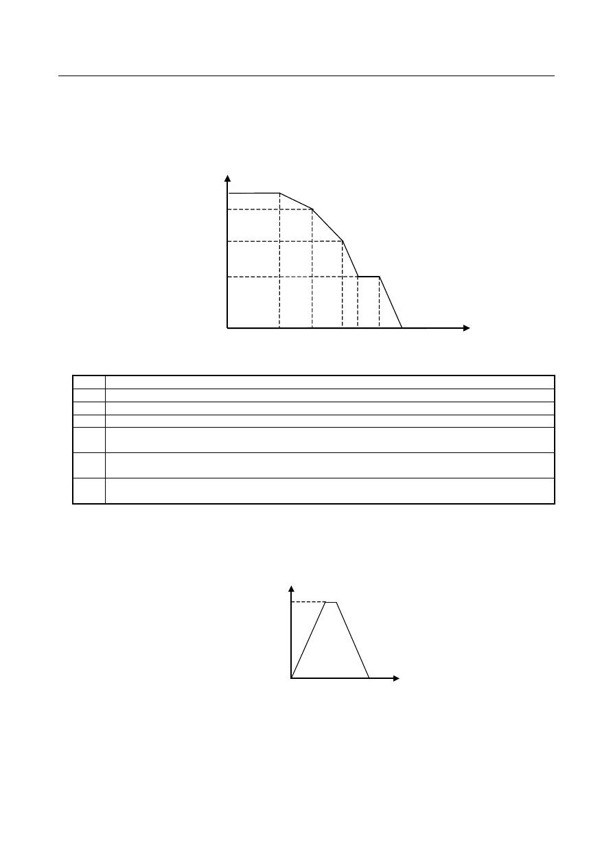
Fig. 10.20.2 (a) is the acceleration/deceleration specified by G96.1/G96.2. 


Rotation 
speed (min

-1

S

0


Time (s)


S

1


S


A

a


A

b


A

c


S

i


A

a


Fig. 10.20.2 (a) 


S

0


Parameter No. 11020 setting (acceleration/deceleration is switched at a rotation speed of S

(min

-1

).) 

S

1


Parameter No. 11021 setting (acceleration/deceleration is switched at a rotation speed of S

(min

-1

).) 

Command-specified rotation speed (min

-1

Si 

Spindle indexing speed (min

-1

) parameter No. 11012 

Aa 

Parameter No. 11030 setting (acceleration/deceleration (min

-1

/s) used between rotation speeds 0 and S

(span 1)) 

A

b


Parameter No. 11031 setting (acceleration/deceleration (min

-1

/s) used between rotation speeds S

and S

(span 2)) 

Ac 

Parameter No. 11032 setting (acceleration/deceleration (min

-1

/s) used between rotation speeds S

1

 and the 

maximum motor speed S (span 3)) 


Spindle indexing speed during a stop 

If spindle indexing is executed (G96.1) while the rotation tool axis is stopped (with SV rotation control 
mode being ON), indexing is performed within one rotation, so that the spindle indexing speed (No. 
11012) may not be attained. 


Spindle speed(min

-1

Si


Time (sec)


A

a


A

a


B-64693EN-1/01


10. SPINDLE SPEED FUNCTION


- 1811 - 

Spindle indexing command (absolute coordinate/machine coordinate) 

Using bit 0 (SIC) of parameter No. 11005 can select which coordinate system, absolute or machine, is to 
be used in spindle indexing. 
 
Example: 
 

If the difference between the machine and absolute coordinates  (machine coordinate –  absolute 
coordinate) is 100.000: 

Spindle indexing performed by turning the SV speed  control  mode signal SRVON<Gn521> 
OFF (“1” to “0”) or issuing a spindle indexing 


G code (with no R specified) 
1. 

If bit 0 (SIC) of parameter No. 11005 = 0: 


Spindle indexing is performed with a machine  coordinate  of 100.000 and an absolute 
coordinate of 0.000. 

2. 

If bit 0 (SIC) of parameter No. 11005 = 1: 


Spindle indexing is performed with a machine  coordinate  of 0.000 and an absolute 
coordinate of 260.000. 

G code-based spindle indexing (with R specified) 


Assuming that spindle indexing is specified with R100.000: 
1. 

If bit 0 (SIC) of parameter No. 11005 = 0: 


Spindle indexing is performed with a machine coordinate of  200.000 and an absolute 
coordinate of 100.000. 

2. 

If bit 0 (SIC) of parameter No. 11005 = 1: 
Spindle indexing is performed with a machine  coordinate  of 100.000 and an absolute 
coordinate of 0.000. 


  - 

Example program commands 

1. 

A move command is issued to the spindle, using G96.2. The  spindle starts moving, and the 
execution of the next block begins. 
The spindle keeps moving even when any other block is being executed. 
(The spindle indexing signal SPP<Fn522> is “1” during spindle indexing.) 

2. 

When another command is issued to the spindle, G96.3 is used to  heck in advance whether the 
spindle has finished moving. 
If the spindle is still moving (the spindle indexing signal is on), the CNC enters a wait state. If the 
spindle has finished moving, the command is issued to cause the spindle to start moving. 


Example: Command not waiting for spindle indexing to finish and command checking whether spindle 

indexing has finished (parameter No. 3781 (S1) = 1) 

Program command 

Operation 

G96.2 P1 R270.0 ; 

Command not waiting for spindle indexing to finish. 
The first spindle S1 moves to 270.0. 

G01 X10.0 Y20.0 F1000.0 ; 

Starts cutting feed. No wait for spindle indexing to finish. 

G02 X50.0 Y100.0 R50.0 ; 

Starts circular interpolation. No wait for spindle indexing to finish. 

G96.3 P1 ; 

Checks whether spindle indexing has finished. 

M29 S100 P1 ; 
G84 X10.0 Y 20.0 R-5.0 Z-20.0 

Starts rigid tapping if the spindle indexing signal is 0. 
Waits for rigid tapping command if the spindle indexing signal is 1. 


Notes 

1. 

Spindle speed override signals and spindle stop signal are invalid from the cancellation of SV speed 
control mode to the completion of spindle indexing. 

-


1st spindle speed override signal SOV0 to SOV7<Gn030> 

-


2nd spindle speed override signal SOV20 to SOV27<Gn376> 

-


3rd spindle speed override signal SOV30 to SOV37<Gn377> 

-


4th spindle speed override signal SOV40 to SOV47<Gn378> 

-


Spindle stop signal *SSTP<Gn029.6> 

10. SPINDLE SPEED FUNCTION


B-64693EN-1/01


- 1812 - 

-


Individual spindle stop signals *SSTP1, *SSTP2, *SSTP3, *SSTP4<Gn027.3, Gn027.4,   

Gn027.5>, <Gn026.6> 

2. 

When the SV speed control mode is canceled, the spindle speed clamp is valid to the spindle speed 
command clamp (Function to spindle speed clamp by value set to internal relay address (R) of PMC 
specified by parameter No. 3773). Even if internal relay address (R) of PMC is changed from the 
cancellation of SV speed control mode  to the completion of spindle indexing, the spindle speed 
clamp is not changed. 

3. 

Specify an M code not involved in buffering as an M code to be used as a command for switching 
the SV speed control mode (parameters Nos. 3411 to 3420 and 11290 to 11299). 

4. 

M code for switching the SV speed control mode must be specified in an independent block. When 
using multiple M commands in a single block, the M code must be specified as the first M 
command. 

5. 

G96.1, G96.2, G96.3, G96.4, and M code for switching the SV speed control mode must be 
specified in the path to which the spindle of interest belongs. 

6. 

After G96.2 command, command G96.3 before commanding move command such as rapid traverse 
(G00) or cutting feed (G01) to rotation axis. Move command is specified  without commanding 
G96.3, alarm PS0445 “ILLEGAL AXIS OPERATION” is issued. 

7. 

If G96.3 is not commanded after G96.2 command, SV speed control mode is not canceled. For 
example, reset before G96.2 command. Cancel the mode before issuing the axis move command. 

8. 

If the spindle stops rotating because of G96.1, G96.2, the spindle speed command output becomes 0. 
To cause the spindle to restart rotating, place the spindle in the SV speed control mode, and then, 
issue an S command. 

9. 

Spindle indexing is enabled  only in the SV speed control mode.  In any mode other than the SV 
speed control mode, use ordinary positioning. 

10.  If the specified spindle indexing speed is 0, the  acceleration/deceleration switching rotation speed 

(stage 1) (parameter No. 11020) is used as the actual spindle indexing speed. 

11.  G96.1, G96.2, G96.3, G96.4 cannot be commanded for settings other than multi-spindle control type 

P. 


Signal 

Spindle indexing signal for each axis SPP1 to SPP8<Fn522> 

  [Classification]  Output signal 
 

[Function]  These signals inform that spindle indexing for the respective axes is in progress. 


[Output cond.]  The signals are “1” if: 

Spindle indexing for the respective axes has not finished. 

The signals are “

0” if:


Spindle indexing for the respective axes has finished. 


Signal address 


#7 

#6 

#5 

#4 

#3 

#2 

#1 

#0 

Fn522 


SPP8 

SPP7 

SPP6 

SPP5 

SPP4 

SPP3 

SPP2 

SPP1 


Parameter 


#7 

#6 

#5 

#4 

#3 

#2 

#1 

#0 

11005 


SIC 


[Input type]  Parameter input 


[Data type]  Bit 


#0  SIC

  Spindle indexing is: 

0: 

Performed based on absolute coordinates. 

1: 

Performed based on machine coordinates. 


B-64693EN-1/01


10. SPINDLE SPEED FUNCTION


- 1813 - 

11012 


Spindle indexing speed for each axis 


[Input type]  Parameter input 


[Data type]  2-word axis 


[Unit of data]  min

-1 

[Valid data range]  0 to 99999999 

In spindle control with servo motor, set the spindle indexing speed for each axis. 
If 0 is set, the spindle indexing speed is assumed to be the setting of parameter No. 11020 
(speed (S

0

) for switching acceleration/ deceleration for each axis). 


10.20.3 

Speed-up of Spindle Indexing Function 

Overview 

In conventional spindle indexing, spindle indexing to the specified position after the speed was 
accelerated or was decelerated up to the spindle indexing speed was executed.   
In this function, the spindle indexing is executed directly to the specified position. The spindle indexing 
time can be reduced. 
 

Explanation 

When bit 1 (HSP) of parameter No. 11002 is set to 1, spindle indexing when the spindle rotates is sped up. 
When the spindle has stopped, the spindle indexing is the same as the conventional the spindle indexing. 
 

Format 

The command format for this type of the spindle indexing is the same as for the conventional type of the 
spindle indexing. 
For details, see “Spindle Indexing” of the conventional type. 
 

Speed-up of Spindle Indexing Function 

In the following cases, the spindle indexing speed up is executed. 

- G96.1(G96.2) is specified during spindle rotation 
- SV speed control mode signals SRVON<Gn521> is set to ”0” during spindle rotation 

In the following, the above-mentioned operation is described, "SV speed control mode off". 
 

Allowable spindle speed of spindle indexing (Parameter(No.11019)) 

Set the allowable spindle speed of the spindle indexing in parameter No. 11019. 
 
(1)


When the SV speed control mode is canceled, the spindle speed is higher than the allowable spindle 
speed. Decelerates from the spindle speed when the SV speed control mode is canceled, and the 
spindle indexing is executed to the specified position. 


10. SPINDLE SPEED FUNCTION


B-64693EN-1/01


- 1814 - 


Rotation speed (min

-1

S

T


Time(s)


S

1


S


A

a


A

b


A

c


S

0


Spindle indexing signal 
SPP<Fn522> 

Allowable   
spindle speed 

SV speed control mode OFF 


Fig. 10.20.3 (a)  Spindle speed is higher than the allowable spindle speed 


(2)


When the SV speed control mode is canceled, the spindle speed is lower than the allowable spindle 
speed. The spindle accelerates once, and the spindle indexing is executed to the specified position. 


S

T


Time(s)


S

1


S


A

a


A

b


S

0


SV speed control mode OFF 

A

a


A

b


Spindle indexing signal 
SPP<Fn522> 

Rotation speed (min

-1

Allowable   
spindle speed 


Fig. 10.20.3 (b)  Spindle speed is lower than the allowable spindle speed 

 
When accelerating during spindle indexing, the spindle speed is clamped at the lowest spindle speed 
among the following spindle speed. 

- Parameter(No.11019)  

Allowable spindle speed of spindle indexing 

- Parameter(No.3772)   

Maximum spindle speed 

- Parameter(No.3741 to 3744) 

Maximum spindle speed (Gear 1


to Gear 4) 

- Spindle speed set to internal relay address (R signal) of PMC specified by parameter(No. 3773) 


B-64693EN-1/01


10. SPINDLE SPEED FUNCTION


- 1815 - 


S

T


S

1


S


A

a


A

b


S

0


SV speed control mode OFF 

A

a


A

b


Rotation speed (min

-1

Spindle indexing signal 
SPP<Fn522> 

Time(s)


Allowable   
spindle speed 


Fig. 10.20.3 (c)  Clamped by allowable spindle speed 

 
The spindle doesn't accelerate when the parameter (No.11019) is 0. The spindle decelerates from the 
spindle speed when the SV speed control mode is canceled, and the spindle indexing is executed to the 
specified position. 
 

Spindle indexing acceleration/deceleration 

As for the spindle speed of the acceleration/deceleration switching and the acceleration after the SV speed 
control mode is canceled, the parameter in Table 10.20.3 is applied as shown in Fig. 10.20.3 (a) to Fig. 
10.20.3 (c). 
 

Table 10.20.3  Parameters for acceleration during spindle indexing 

S

0


Acceleration switching speed (S

0

) [min

-1

] (parameter No.11020) 

S

1


Acceleration switching speed (S

1

) [min

-1

] (parameter No.11021) 

Specified rotation speed[min

-1

S

T


Allowable spindle speed of spindle indexing[min

-1

] (parameter No.11019) 

A

a


Acceleration 1 [min

-1

/s] (parameter No.11030) 

A

b


Acceleration 2 [min

-1

/s] (parameter No.11031) 

A

c


Acceleration 3 [min

-1

/s] (parameter No.11032) 


Spindle indexing signal for each axis 

The spindle indexing signal SPP<Fn522> is “1” form Fig. 10.20.3 (a) to Fig. 10.20.3 (c) during spindle 
indexing until the spindle decelerates and stops after the SV speed control mode is canceled 
 

Notes 

1.  Spindle speed override signals and spindle stop signal are invalid from the cancellation of SV speed 

control mode to the completion of spindle indexing. 

-


1st spindle speed override signal SOV0 to SOV7<Gn030> 

-


2nd spindle speed override signal SOV20 to SOV27<Gn376> 

-


3rd spindle speed override signal SOV30 to SOV37<Gn377> 

-


4th spindle speed override signal SOV40 to SOV47<Gn378> 

-


Spindle stop signal *SSTP<Gn029.6> 

-


Individual spindle stop signals *SSTP1, *SSTP2, *SSTP3, *SSTP4<Gn027.3, Gn027.4,   

Gn027.5>, <Gn026.6> 

2.  When the SV speed control mode is canceled, the spindle speed clamp is valid to the spindle speed 

command clamp (Function to spindle speed clamp by value set to internal relay address (R) of PMC 
specified by parameter No. 3773). Even if internal relay address (R) of PMC is changed from the 

10. SPINDLE SPEED FUNCTION


B-64693EN-1/01


- 1816 - 

cancellation of SV speed control mode to the completion of spindle indexing, the spindle speed 
clamp is not changed. 

3.  Specify an M code not involved in buffering as an M code to be used as a command for switching the 

SV speed control mode (parameters Nos. 3411 to 3420 and 11290 to 11299). 

4.  M code for switching the SV speed control mode must be specified in an independent block. When 

using multiple M commands in a single block, the M code must be specified as the first M 
command. 

5.  G96.1, G96.2, G96.3, G96.4, and M code for switching the SV speed control mode must be specified 

in the path to which the spindle of interest belongs. 

6.  After G96.2 command, command G96.3 before commanding move command such as rapid traverse 

(G00) or cutting feed (G01) to rotation axis. Move command is specified  without commanding 
G96.3, alarm PS0445 “ILLEGAL AXIS OPERATION” is issued. 

7.  If G96.3 is not commanded after G96.2 command, SV speed control mode is not canceled. For 

example, reset before G96.2 command. Cancel the mode before issuing the axis move command. 

8.  If the spindle stops rotating because of G96.1, G96.2, the spindle speed command output becomes 0. 

To cause the spindle to restart rotating, place the spindle in the SV speed control mode, and then, 
issue an S command. 

9.  Spindle indexing is enabled only in the SV speed control mode. In any mode other than the SV speed 

control mode, use ordinary positioning. 

10. G96.1, G96.2, G96.3, G96.4 cannot be commanded for settings other than multi-spindle control type 

P. 


Signal 

Spindle indexing signal for each axis SPP1 to SPP8<Fn522> 

  [Classification]  Output signal 
 

[Function]  These signals inform that spindle indexing for the respective axes is in progress. 


[Output cond.]  The signals are “1” if: 

Spindle indexing for the respective axes has not finished. 

The signals are “0” if: 

Spindle indexing for the respective axes has finished. 


Signal address 


#7 

#6 

#5 

#4 

#3 

#2 

#1 

#0 

Fn522 


SPP8 

SPP7 

SPP6 

SPP5 

SPP4 

SPP3 

SPP2 

SPP1 


Parameter 


#7 

#6 

#5 

#4 

#3 

#2 

#1 

#0 

11002 


HSP 


[Input type]  Parameter input 


[Data type]  Bit axis 


#1  HSP

  Speed-up of Spindle indexing is: 

0:  Disabled. 
1:  Enabled. 


NOTE 


This parameter is Automatic setting parameter. For details, refer to 
the appendix "Automatic setting / Initial setting parameter" in this 
manual. 


B-64693EN-1/01


10. SPINDLE SPEED FUNCTION


- 1817 - 

11019 


Allowable spindle speed of spindle indexing 


[Input type]  Parameter input 


[Data type]  2-word axis 


[Unit of data]  min

-1 

[Valid data range]  0 to 99999999 

When bit 1 (HSP) of parameter No. 11002 is 1, allowable spindle speed of speed-up 
spindle indexing is set. 
When the SV speed control mode is canceled, the spindle speed is lower than the this 
parameter setting value, the spindle accelerates to this parameter setting value 
The spindle doesn't accelerate when this parameter is 0. The spindle decelerates from the 
spindle speed when the SV speed control mode is canceled, and the spindle indexing is 
executed to the specified position. 


10.20.4 

Rigid Tapping with Servo Motor 

Format 

The command format for this type of rigid tapping is the same as for  the conventional type of rigid 
tapping. 
For details, see “Rigid Tapping” of the conventional type. 
 

NOTE 


Using rigid tapping commands requires putting the rotation axis servo motor in 
the position control mode in advance. If the servo motor is rotating, cause it to 
exit the SV speed control mode by issuing G96.1/G96.2. The SV speed control 
mode in-progress signal SVREV<Fn521> can be used to check what mode the 
servo motor rotation axis is in. 


Rigid tapping specification 

Feedrate 

For rigid tapping, the feedrate of a drilling axis is one specified in an F command, and that of the spindle 
is S × the amount of movement per live tool axis rotation (parameter No. 11011) [deg/min]. 
Feed per minute and feed per revolution are detailed later. 
During rigid tapping, the spindle speed is limited by a parameter for specifying the maximum cutting 
feedrate for the axis used as a live tool axis, that is, parameter No. 1430 (or No. 1432 if look-ahead 
acceleration/ deceleration before interpolation is enabled). 
Usually, the upper end of the maximum cutting feed range that can be specified by parameter No. 1430 or 
No. 1432 is 999999.999[deg/min] (equivalent to S2778 [min

-1

]). For live tool axes specified for use in 

rigid tapping (bit 3 (IRC) of parameter No. 1408 = 1), the actual spindle speed is limited to within 10 
times the setting of the maximum cutting feedrate parameter. 
Example: 
Maximum cutting feedrate parameter No. 1430 = 360000 
Limit to the maximum spindle speed 360000×10 = 3600000 [deg/min] (S10000 [min

-1

]) 


  CAUTION 


Make the tapper thread pitch equal to one specified by the program (F, S). 
Otherwise, the tool or workpiece may be damaged. 


Content      ..     230      231      232      233     ..