FANUC Series 0i-MODEL F Plus. CONNECTION MANUAL (FUNCTION) - page 233
 

  Index      Manuals     FANUC Series 0i-MODEL F Plus. CONNECTION MANUAL (FUNCTION) B-64693EN-1/01


Search            copyright infringement  


Content      ..     231      232      233      234     ..


FANUC Series 0i-MODEL F Plus. CONNECTION MANUAL (FUNCTION) - page 233


10. SPINDLE SPEED FUNCTION


B-64693EN-1/01


- 1818 - 

Acceleration/deceleration control 

Acceleration/deceleration after interpolation 

In rigid tapping with servo motor, unlike the conventional type of 
rigid tapping, it is possible to apply linear acceleration/deceleration of constant acceleration/deceleration 
time type and bell-shape acceleration/deceleration. 
Resetting bit 0 (SRBx) of parameter No. 11001 to 0 makes it possible to apply linear 
acceleration/deceleration after interpolation of constant acceleration time type. Setting the bit to 1 makes 
it possible to apply bell-shape acceleration/deceleration after interpolation of constant acceleration time 
type. 
The time constant for each gear is specified in parameters Nos. 11060  to 11063. If bit 2 (TDR) of 
parameter No. 5201 = 1, the tool extraction time constant for each gear is specified in parameter 
Nos. 11065 to 11068. Specify each of these parameters for the live tool axis used in rigid tapping. 
The acceleration/deceleration types and time constants used for drilling axes are set to the same values as 
for live tool axes. 
 

NOTE 


Time constants specified for rigid tapping with servo motor are different from 
those for the conventional type of rigid tapping. 

 
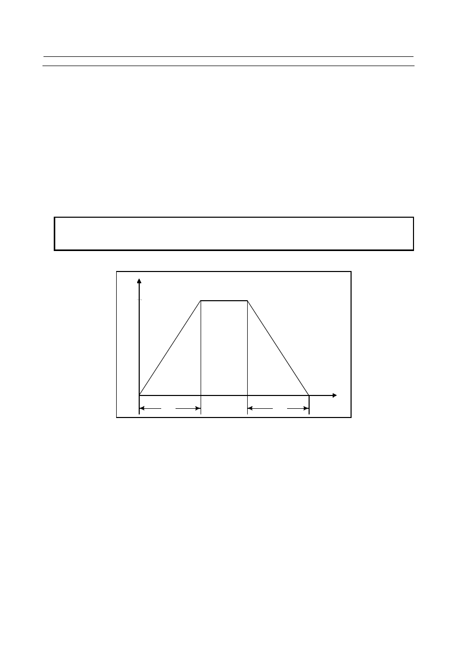
Example: Parameter settings are: Time constant (TC) = 800 msec and speed (S) = 4000 min

-1


min

-1


4000


msec


800


800


Acceleration/deceleration before interpolation 

If AI contour control I or II can be  used in rigid tapping with servo  motor, issuing a rigid tapping 
command in the  "acceleration/deceleration before look-ahead interpolation" mode  makes it possible to 
apply acceleration/deceleration before look-ahead  interpolation to this type of rigid tapping. 
Acceleration/deceleration before look-head interpolation is effective when the AI contour control mode is 
ON. For details, see the Subsection of "AI Contour Control I and AI Contour Control II." 
Parameter No. 11050 is used to specify the maximum allowable acceleration value for 
acceleration/deceleration interpolation used in rigid tapping. Parameter No. 11051 is used to specify the 
acceleration change time for look-ahead bell-shape acceleration/deceleration before interpolation. As for 
look-ahead acceleration/deceleration before interpolation used in rigid tapping, the maximum allowable 
acceleration value is 100000 (deg/s

2

). 

It is possible to change a speed of up to S1000 (min

-1

) (equivalent to 360000 (deg/min) in 60 (ms). 

The time constant (parameter No. 11052) for cutting feed acceleration/deceleration after interpolation 
usable in the "look-ahead acceleration/deceleration before interpolation" mode is a constant-time type. 


B-64693EN-1/01


10. SPINDLE SPEED FUNCTION


- 1819 - 

NOTE 


Specify the same time constant for both drilling and live tool axes. Otherwise, it 
is likely that the machine may malfunction. 


Feedrate clamp by parameter No.8465 

In AI contour control, the maximum allowable feedrate  is set by parameter No.8465. The maximum 
allowable feedrate of rigid tapping with servo motor during AI contour control is also set by parameter 
No.8465. If bit 0 (NCL) of parameter No.11003 is set to 1, the maximum allowable feedrate  of rigid 
tapping with servo motor during AI contour control is not clamped by parameter No.8465. However, 
maximum allowable feedrate  set by parameter No.1432 is available regardless of bit 0 (NCL) of 
parameter No.11003. 
 

Ignoring feedrate commands 

When AI contour control II is enabled and bit 7 (NOF) of parameter No.8451 is set to 1, all feedrate 
commands are ignored and feedrate  is specified by parameter No.8465. If bit 1 (FEN) of parameter 
No.11003 is set to 1, feedrate of rigid tapping with servo motor can be specified by machining program. 
But feedrate is limited by maximum allowable feedrate of parameter No.1432. 
 

Reference position return 

With this function, it is impossible to perform spindle orientation at the start of rigid tapping. Before 
issuing a rigid tapping command, perform spindle indexing or positioning at a point where drilling should 
begin. For details, see Subsection of "Spindle Indexing Function." 
 

Diagnosis data 

Also in rigid tapping with servo motor, information about rigid tapping is displayed on the  diagnosis 
display screen. See Subsection of “Diagnosis Display” for what information is displayed. 
 

Notes 

If the pitch is very small or the amount of travel along the drilling axis is large, the amount of travel along 
the rotation axis becomes large, possibly resulting in alarm PS0003, “TOO MANY DIGITS”. 
 

Parameter 

1430 


Maximum cutting feedrate for each axis 


[Input type]  Parameter input 


[Data type]  Real axis 


[Unit of data]  mm/min, inch/min, deg/min (machine unit) 

[Min. unit of data]  Depend on the increment system of the applied axis 
[Valid data range]  Refer to the standard parameter setting table (C) 

(When the increment system is IS-B, 0.0 to +999000.0) 
Specify the maximum cutting feedrate for each axis. 
 

1432 


Maximum cutting feedrate for all axes in the acceleration/deceleration before interpolation 


[Input type]  Parameter input 


[Data type]  Real axis 


[Unit of data]  mm/min, inch/min, deg/min (machine unit) 

[Min. unit of data]  Depend on the increment system of the applied axis 
[Valid data range]  Refer to the standard parameter setting table (C) 

(When the increment system is IS-B, 0.0 to +999000.0) 

10. SPINDLE SPEED FUNCTION


B-64693EN-1/01


- 1820 - 

Set a maximum cutting feedrate for each axis in the look-ahead acceleration/deceleration 
before interpolation mode such as AI contour control. When this parameter is set to 0 or 
the  look-ahead  acceleration/deceleration  before  interpolation  mode is not set, the 
maximum cutting feedrate set in parameter No. 1430 is used. 


#7 

#6 

#5 

#4 

#3 

#2 

#1 

#0 

8451 


NOF 


[Input type]  Setting input 


[Data type]  Bit path 


#7  NOF

  In AI contour control, an F command is: 

0: 

Not ignored. 

1: 

Ignored. 

When this parameter is set to 1, the specification of the maximum allowable feedrate set 
in parameter No. 8465 is assumed. 
 

8465 


Maximum allowable feedrate for AI contour control 


[Input type]  Setting input 


[Data type]  Real path 


[Unit of data]  mm/min, inch/min, deg/min (input unit) 

[Min. unit of data]  Depend on the increment system of the reference axis 
[Valid data range]  Refer to the standard parameter setting table (C) 

(When the increment system is IS-B, 0.0 to +999000.0) 
This parameter sets the maximum allowable feedrate for contour control. 
If a feedrate higher than the setting of this parameter is specified in the AI contour control 
mode, the feedrate is clamped to that set in this parameter. 
If this parameter is set to 0, no clamping is performed. 
When bit 7 (NOF) of parameter No. 8451 is set to 1, the tool moves, assuming that the 
feedrate set in this parameter is specified. If 0 is set in this parameter at this time, a 
movement is made at the specified feedrate. 


#7 

#6 

#5 

#4 

#3 

#2 

#1 

#0 

11001 


SRBx 


[Input type]  Parameter input 


[Data type]  Bit axis 


#0  SRBx

  Acceleration/deceleration after interpolation in cutting feed during  rigid tapping with 

servo motor is: 
0: 

Linear acceleration/deceleration. 

1: 

Bell-shaped acceleration/deceleration. 


#7 

#6 

#5 

#4 

#3 

#2 

#1 

#0 

11003 


FEN 

NCL 


[Input type]  Parameter input 


[Data type]  Bit path 


#0  NCL

  In AI contour control, feedrate of rigid tapping with servo motor is: 

0: 

limited by maximum allowable feedrate of parameter No.8465. 

1: 

not limited by maximum allowable feedrate of parameter No.8465. 

Maximum allowable feedrate  of parameter No.1432 is enabled regardless of this 
parameter. 

B-64693EN-1/01


10. SPINDLE SPEED FUNCTION


- 1821 - 


#1  FEN

  When ignoring feedrate commands is enabled (bit 7 (NOF) of parameter No.8451 is 1), 

feedrate of rigid tapping with servo motor is specified by: 
0: 

parameter No.8465. 

1: 

machining program. 

Maximum allowable feedrate  of parameter No.1432 is enabled regardless of this 
parameter. 
 

11050 


Maximum allowable acceleration rate in acceleration/deceleration before interpolation for each axis in 

rigid tapping 


[Input type]  Parameter input 


[Data type]  Real axis 


[Unit of data]  mm/sec

2

, inch/sec

2

, deg/sec

2

 (machine unit) 

[Min. unit of data]  Depend on the increment system of the applied axis 
[Valid data range]  Refer to the standard parameter setting table (D) 

(When the machine system is metric system, 0.0 to +100000.0. When the machine system 
is inch system, 0.0 to +10000.0) 
Set a maximum allowable acceleration rate in  look-ahead  acceleration/  deceleration 
before interpolation for each axis. 
If a value greater than 100000.0 is set, the value is clamped to 100000.0. If 0 is set, the 
specification of 100000.0 is assumed. If 0  is set for all  axes, however,  look-ahead 
acceleration/deceleration before interpolation is not performed. 
 

11051 


Acceleration change time of bell-shaped acceleration/deceleration before interpolation in rigid tapping 


[Input type]  Parameter input 


[Data type]  2-word path 


[Unit of data]  msec 

[Valid data range]  0 to 200 

Set an acceleration change time of look-ahead  bell-shaped  acceleration/  deceleration 
before interpolation (time for changing from the state of constant federate (A) to the state 
of constant  acceleration/deceleration  (C) at the acceleration  rate calculated  from  the 
acceleration rate set in parameter No. 11050: time of (B) in the Fig. 10.20.4 (d)). 


Speed in tangent direction 

Based on the setting of parameter 
No. 11050, an optimum inclination 
is calculated automatically. 

Set time in parameter No. 11051. 

(A) 

(B) 

(B) 

(B) 

(B) 

(A) 

(A) 

(C) 

(C) 


Fig. 10.20.4 


11052 


Time constant for acceleration/deceleration after cutting feed interpolation in the 

acceleration/deceleration before interpolation mode in rigid tapping 


[Input type]  Parameter input 


[Data type]  Word axis 


[Unit of data]  msec 

10. SPINDLE SPEED FUNCTION


B-64693EN-1/01


- 1822 - 

[Valid data range]  0 to 4000 

In the look-ahead  acceleration/deceleration before interpolation mode as in AI  contour 
control,  not the ordinary time constant (parameter No. 1622)  but the value of  this 
parameter is used. 
Be sure to specify the same time constant value for all axes except for  a special 
application. 
If different values are set, correct linear and circular figures cannot be obtained. 
 

11060 


Time constant for acceleration/deceleration after cutting feed interpolation in rigid tapping (first gear) 


11061 


Time constant for acceleration/deceleration after cutting feed interpolation in rigid tapping (second 

gear) 


11062 


Time constant for acceleration/deceleration after cutting feed interpolation in rigid tapping (third gear) 


11063 


Time constant for acceleration/deceleration after cutting feed interpolation in rigid tapping (fourth gear) 


[Input type]  Parameter input 


[Data type]  Word axis 


[Unit of data]  msec 

[Valid data range]  0 to 4000 

For the time constants in rigid tapping with servo motors, parameters Nos. 11060 to 
11063 are used, not parameters Nos. 5261 to 5264. 
Set these parameters with a live tool axis in rigid tapping. 
 

11065 


Time constant for acceleration/deceleration after cutting feed interpolation in rigid tapping extraction 

(first gear) 


11066 


Time constant for acceleration/deceleration after cutting feed interpolation in rigid tapping extraction 

(second gear) 


11067 


Time constant for acceleration/deceleration after cutting feed interpolation in rigid tapping extraction 

(third gear) 


11068 


Time constant for acceleration/deceleration after cutting feed interpolation in rigid tapping extraction 

(fourth gear) 


[Input type]  Parameter input 


[Data type]  Word axis 


[Unit of data]  msec 

[Valid data range]  0 to 4000 

If bit 2 (TDR) of parameter No. 5201 is set to 1, for the time constants in rigid tapping 
extraction with servo motors, parameters Nos. 11065 to 11068 are used, not parameters 
Nos. 5271 to 5274. 
Set these parameters with a live tool axis in rigid tapping. 
 

B-64693EN-1/01


10. SPINDLE SPEED FUNCTION


- 1823 - 

10.20.5 

Threading, Feed per Revolution, and Constant Surface Speed 
Control 

Overview 

The following are supported in spindle control with servo motor: 

- Feed per revolution 
- Threading 
- Constant surface speed control 


  - 

Feed per revolution 

The feedrate for feed per revolution is obtained from the separate  detector linked to the spindle. If the 
detector incorporated in the servo motor is used, the feedrate is calculated from the servo motor rotation 
speed and gear ratio. 
Which detector to use is specified by bit 1 (OPTx) of parameter No. 1815. 
See Subsection of  "Feed Per Revolution/Manual Feed Per  Revolution," for explanations about feed per 
revolution. 


  - 

Threading 

Threading can be performed by reading the one-rotation signal from a  separate detector linked to the 
spindle. 
In a configuration in which the spindle and motor are linked at a specific gear ratio, a detector linked to 
the spindle at a gear ratio of 1:1 is necessary. 
See Section of “THREADING,” for explanations about threading. 


  - 

Constant surface speed control 

Using the S code (value following the letter S) to specify a surface speed (m/min or feet/min) enables the 
speed of the spindle to be controlled so that the surface speed is kept constant with regard to any change 
in the tool position. 
As for gear change, use T type gear change. 
See Section of  “CONSTANT SURFACE SPEED CONTROL,” for  explanations about constant surface 
speed control. 


  - 

Multi-spindle control 

If the machine is equipped with a spindle controlled  axis and spindle with servo  motor, using rotation 
commands requires the multi-spindle control. 
As for gear change, use T type gear change. 
See Section of “MULTI-SPINDLE CONTROL,” for explanations about multi-spindle control. 


Format 

- Feed per revolution, threading, and constant surface speed control 

The command format for feed per revolution, threading, and constant  surface speed control explained 
above is the same as for the ordinary types of feed per revolution, threading, and constant surface speed 
control. 
 

Examples 

The following are examples in which the second spindle (C axis) is used for servo motor rotation control 
and position control. 
(The G code system A in lathe system is selected.) 
 

10. SPINDLE SPEED FUNCTION


B-64693EN-1/01


- 1824 - 

  - 

Feed per revolution 

Program command 

Operation 

M*** ; 

The C axis rotation control mode is turned ON. 

M03 S100 P2 ; 

The C axis rotates at 100 min

-1

G99 G01 Z-100. F10. ; 

The Z axis moves at a feed-per-revolution speed of 1000 mm/min. 

M*** ; 

The C axis position control mode is set to ON (rotation control mode OFF). 
The spindle stops with C = 0.000. 


  - 

Threading 

Program command 

Operation 

M*** ; 

The C axis rotation control mode is set to ON. 

M03 S100 P2 ; 

The C axis rotates at 100 min

-1

G32 Z-100.0 F1.0 ; 

The Z-axis moves at a threading speed of 100 mm/min with a pitch of 1.000 mm. 

M*** ; 

The C axis position control mode is set to ON (rotation control mode OFF). 
The axis stops with C = 0.000. 


  - 

Constant surface speed control 

Program command 

Operation 

M*** ; 

The C axis rotation control mode is set to ON. 

M03 S100 P2 ; 

The C axis rotates at 100 min

-1

G96 S12 P2.0 ; 

The constant surface speed control mode is set to ON. The C axis rotates at 12 m/min. 

G01 X100.0 Z20.0 ; 

The tool moves in the constant surface speed control mode. 

G97 S100 P2.0 ; 

The constant surface speed control mode is set to OFF. The C axis rotates at 100 min

-1

M*** ; 

The C axis position control mode is set to ON (rotation control mode OFF). 
The axis stops with C = 0.000. 


Parameters 


#7 

#6 

#5 

#4 

#3 

#2 

#1 

#0 

1815 


OPTx 


[Input type]  Parameter input 


[Data type]  Bit axis 


NOTE 


When this parameter is set, the power must be turned off before 
operation is continued. 


#1  OPTx

  The separate position detector is: 

0: 

Not to be used (semi-closed system) 

1: 

To be used (full-closed system) 


NOTE 


In case of using the absolute position detector (bit 5 (APCx) of 
parameter No.1815 is set to 1), please set the following parameters 
that correspond to the absolute position detector which is actually 
used. 

parameter No.1815#6, No.1815#0, No.1817#3, No.1868,   


No.2275#1, No.2394 

If these parameters are not set correctly, the machine coordinates 
are not correctly established at power-on. 

B-64693EN-1/01


10. SPINDLE SPEED FUNCTION


- 1825 - 


2455 


Integral part (

α

) of the number of pulses for one rotation 


[Data type]  Word axis 

[Valid data range]  0 to 32767 

If 0 is specified, no threading counter is output. 
If the specified range is exceeded, an invalid parameter alarm SV0417 is issued. 
(Detail number of diagnosis data No. 0352: 4553) 
 

2456 


Exponential part (

β

) of the number of pulses for one rotation 


[Data type]  Word axis 

[Valid data range]  0 to 12 

If the specified range is exceeded, an invalid parameter alarm SV0417 is issued. 
(Detail number of diagnosis data No. 0352: 4563) 
 

Number of pulses per detector rotation (Np) = α×2

β


Determine α and β so that the above expression is satisfied. 
For a closed system is in use, specify a value that corresponds to separate detector pulses. 


Setting examples 

System 

Np(pulse/rev) 

No.2455 

No.2456 

Remarks 

α

i

 Pulsecoder 

Np=1,000,000 

16384 


AB phase (12000p/rev) 

Np=12,000 

12000 


Serial output type rotary 
encoder (million pulses/rev) 

Np=1,000,000 

16384 


Serial output type rotary 
encoder (RCN223,723,220) 

Np=8,000,000 

16384 

10 

No.2275#0 
No.2394 must be 
set. 

5000

λ/rev detector 

+High-resolution serial output 
circuit C or H 

Np=5000

×

512 

=5000

×

2

9


5000 

No.2274#0=1 must 
be set. 

18000

λ/rev detector 

+High-resolution serial output 
circuit C or H 

Np=18000

×

512 

=18000

×

2

9


18000 

No.2274#0=1 must 
be set. 

36000

λ/rev detector 

+High-resolution serial output 
circuit C or H 

Np=36000

×

512 

=18000

×

2

10


18000 

10 

No.2274#0=1 must 
be set. 

5000

λ/rev detector + analog 

SDU 

Np=5000

×

512 

=5000

×

2

9


5000 


18000

λ/rev detector + analog 

SDU 

Np=36000

×

512 

=18000

×

2

10


18000 

10 


36000

λ/rev detector + analog 

SDU 

Np=36000

×

512 

=18000

×

2

10


18000 

10 


2048λ/rev detector + 
Synchronous built-in servo 
motor position detection circuit 

Np= 2,000,000 

16384 


#7 

#6 

#5 

#4 

#3 

#2 

#1 

#0 

11001 


DDMx 


[Input type]  Parameter input 


[Data type]  Bit axis 


Content      ..     231      232      233      234     ..