FANUC Series 0i-MODEL F Plus. CONNECTION MANUAL (FUNCTION) - page 230
 

  Index      Manuals     FANUC Series 0i-MODEL F Plus. CONNECTION MANUAL (FUNCTION) B-64693EN-1/01


Search            copyright infringement  


Content      ..     228      229      230      231     ..


FANUC Series 0i-MODEL F Plus. CONNECTION MANUAL (FUNCTION) - page 230


10. SPINDLE SPEED FUNCTION


B-64693EN-1/01


- 1794 - 

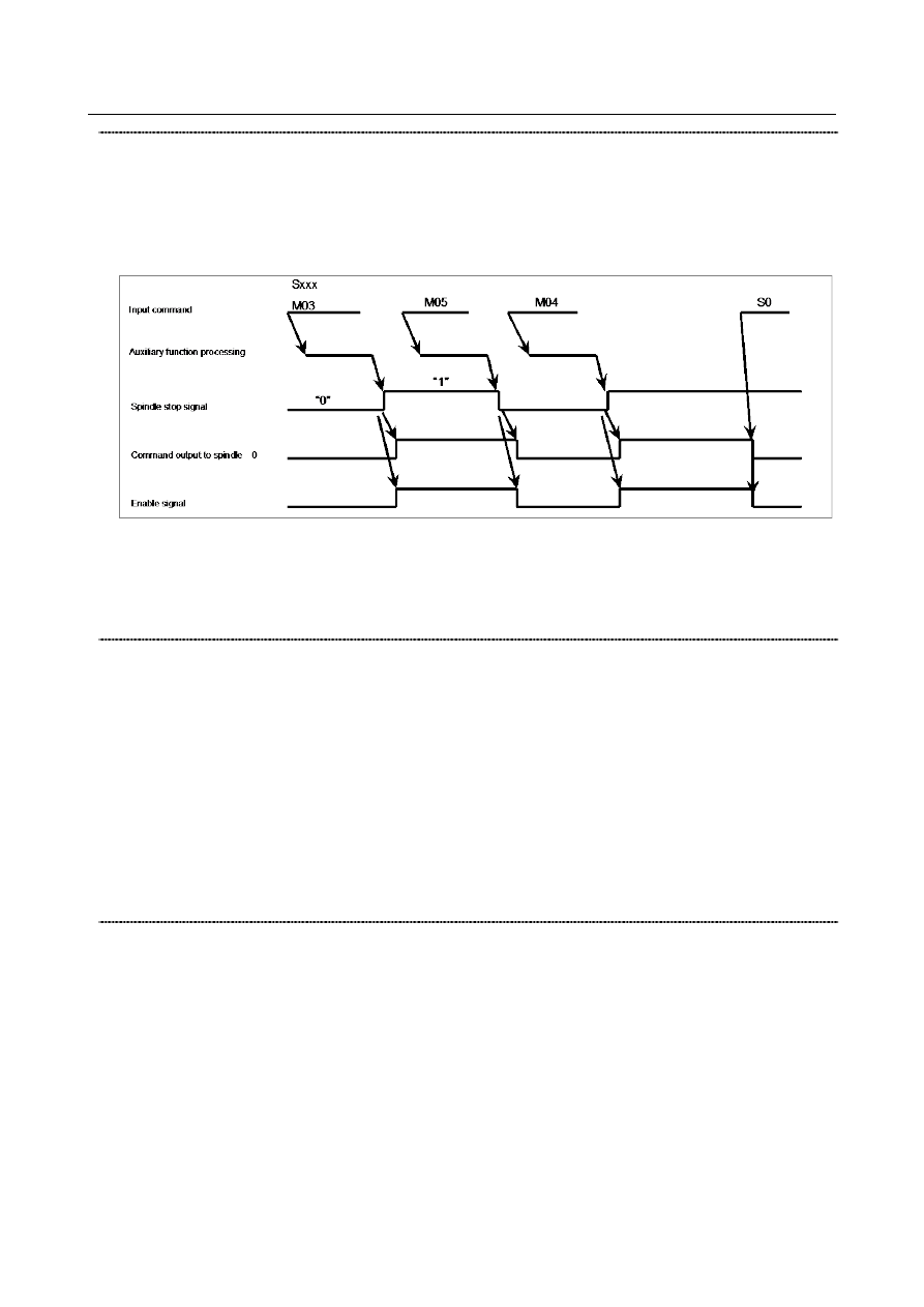
Spindle stop signal *SSTP<Gn029.6> 

  [Classification]  Input signal 
 

[Function]  This signal stops the command output to the spindle. 


[Operation]  When this signal becomes 0, the command output to the spindle becomes 0, resulting in 

the enable signal becoming 0. So, M05 is  not output. When this signal becomes 1, the 
command output to the spindle resumes its previous value, resulting in the enable signal 
becoming 1. 


The timing chart above is illustrative only. To be more precise, follow a timing chart that 
meets the specification of the speed control unit for the spindle motor in use. 

Keep this signal set to 1 unless it is used. 

The CNC uses the commands M03, M04, and M05 to send only  code and strobe 
signals. 


Individual spindle stop signals   
 

*SSTP1<Gn027.3> *SSTP2<Gn027.4> *SSTP3<Gn027.5> *SSTP4<Gn026.6> 

  [Classification]  Input signal 
 

[Function]  These signals are usable only during multi-spindle control. 

They cause the respective spindles to stop. 


*SSTP1  1: Does not make the output to the first spindle 0 min

-1

0: Makes the output to the first spindle 0 min

-1


*SSTP2  1: Does not make the output to the second spindle 0 min

-1

0: Makes the output to the second spindle 0 min

-1


*SSTP3  1: Does not make the output to the third spindle 0 min

-1

0: Makes the output to the third spindle 0 min

-1


*SSTP4  1: Does not make the output to the fourth spindle 0 min

-1

0: Makes the output to the fourth spindle 0 min

-1


Spindle speed override signals SOV0 to SOV7<Gn030> 

  [Classification]  Input signal 
 

[Function]  These signals enable an override of 0% to 254% of the S command value sent to the CNC 

to be applied to the spindle in 1% increments. 


[Operation]  Specify an override value in binary, using the 8 bits SOV0 to SOV7. 

The spindle speed override specified with these signals becomes disabled, and an override 
of 100% is applied to the spindle speed during: 

Tapping cycle (for the M series, G84 and G74 or, for the T series, G84 and G88) 

Threading mode (for the M series, G33 or, for the T series, G32, G92, and G76) 

→  Specify an override of 100% unless this function is used. 

(An override of 0% is applied, preventing spindle rotation.) 


B-64693EN-1/01


10. SPINDLE SPEED FUNCTION


- 1795 - 

Spindle enable signals ENB<Fn001.4> ENB2<Fn038.2> ENB3<Fn038.3> 

ENB4<Fn039.1> 

  [Classification]  Output signal 
 

[Function]  These signals inform whether there is an output to the second, third, or fourth spindle if 

the multi-spindle control is available. 
The signals can be used as a condition for stopping the analog spindle and in PMC ladder 
sequences related to rigid tapping. 
(See Subsection, "Rigid Tapping.") 


[Output cond.]   


ENB  1 if the output to the first spindle control unit is not 0. 

0 if the output to the first spindle control unit is 0. 


ENB2  1 if the output to the second spindle control unit is not 0. 

0 if the output to the second spindle control unit is 0. 


ENB3  1 if the output to the third spindle control unit is not 0. 

0 if the output to the third spindle control unit is 0. 


ENB4  1 if the output to the fourth spindle control unit is not 0. 

0 if the output to the fourth spindle control unit is 0. 


Multi-spindle address P signals MSP00 to MSP15<Fn160.0 to Fn161.7> 

  [Classification]  Output signal 
 

[Function]  These signals output the P value most recently specified by the S_ P_ ; command. 


[Output cond.]  If the address P-based multi-spindle control is enabled (bit 3 (MPP) of parameter No. 

3703 =1), the P value specified by the S_ P_ ; command is output. If no S_ P_ ; has been 
issued since application of the power, the initial P value specified in parameter No. 3775 
is output. 


Signal address 


#7 

#6 

#5 

#4 

#3 

#2 

#1 

#0 

Gn026 


*SSTP4 


Gn027 


*SSTP3 

*SSTP2 

*SSTP1 


Gn029 


*SSTP 


Gn030 


SOV7 

SOV6 

SOV5 

SOV4 

SOV3 

SOV2 

SOV1 

SOV0 


Gn521 


SRVON8 

SRVON7 

SRVON6 

SRVON5 

SRVON4 

SRVON3 

SRVON2 

SRVON1 


Gn523 


SVRVS8 

SVRVS7 

SVRVS6 

SVRVS5 

SVRVS4 

SVRVS3 

SVRVS2 

SVRVS1 


Fn001 


ENB 


Fn038 


ENB3 

ENB2 


Fn039 


ENB4 


Fn160 


MSP07 

MSP06 

MSP05 

MSP04 

MSP03 

MSP02 

MSP01 

MSP00 


Fn161 


MSP15 

MSP14 

MSP13 

MSP12 

MSP11 

MSP10 

MSP09 

MSP08 


Fn521 


SVREV8 

SVREV7 

SVREV6 

SVREV5 

SVREV4 

SVREV3 

SVREV2 

SVREV1 


10. SPINDLE SPEED FUNCTION


B-64693EN-1/01


- 1796 - 

Notes 

Unlike spindle motors, servo motors stop if a servo alarm,  emergency stop, or machine lock 
condition occurs. 

Specify an M code not involved in buffering as an M code to be used as a command for switching 
the SV speed control mode (parameters Nos. 3411 to 3420 and 11290 to 11299). 

M code for switching the SV speed control mode must be specified in an independent block. 

When using multiple M commands in a single block, the M code must be specified as the first M 

command. 

G96.1, G96.2, G96.3, G96.4, and M code for switching the SV speed control mode must be 
specified in the path to which the spindle of interest belongs. 

The actual maximum motor speed is determined by applying a  feed gear factor to the maximum 
motor speed specified in parameter No. 11015. 

If bit 3 (IRC) of parameter No. 1408 is 0, the malfunction prevent function may work at a rotation 
speed of about 2778  min-1. To allow the motor to run at 2778min-1 or faster, set bit  3 (IRC) of 
parameter No. 1408 to 1. If the bit is set to 1,  the command can specify a rotation speed of up to 
about 27778 min

-1

This function must be set for type T gears. 

G96.1, G96.2, G96.3, G96.4 cannot be commanded for settings other than multi-spindle control type 
P. 

Feed axis synchronous control or synchronous control cannot be performed on an axis that is in SV 
rotation control mode. 

As for the axis used for spindle control with a servo motor, disable the setting of bit 7 (ALGx) of 
parameter No. 1814, which adjusts the loop gain in Cs contour control mode to the loop gain of the 
Cs contour control axis, and the setting of parameter No. 3900 and after, which sets the loop gain of 
the axis to interpolate with the Cs contour control axis. Otherwise, the loop gain of the servo axis 
will change suddenly if the system enters Cs contour control mode during rotation control. 

When using spindle control with servo motor, set 1 to bit 3 (FEX) of parameter No.8003. 


Parameter 

The major related parameters are described below. 


#7 

#6 

#5 

#4 

#3 

#2 

#1 

#0 

1006 


ROSx 

ROTx 


[Input type]  Parameter input 


[Data type]  Bit axis 


NOTE 


When at least one of these parameters is set, the power must be 
turned off before operation is continued. 


#0  ROTx

  Setting linear or rotation axis. 


#1  ROSx 


ROSx 

ROTx 

Meaning 

Linear axis 
(1)  Inch/metric conversion is done. 
(2)  All coordinate values are linear axis type. (Is not rounded in 0 to 360

°

(3)  Stored pitch error compensation is linear axis type (Refer to parameter No. 

3624) 

B-64693EN-1/01


10. SPINDLE SPEED FUNCTION


- 1797 - 

ROSx 

ROTx 

Meaning 

Rotary axis (A type) 
(1)  Inch/metric conversion is not done. 
(2)  Machine coordinate values are rounded in 0 to 360

°

. Absolute coordinate 

values are rounded or not rounded by bits 0 (ROAx) and 2 (RRLx) of 
parameter No. 1008. 

(3)  Stored pitch error compensation is the rotation type. (Refer to parameter 

No. 3624) 

(4)  Automatic reference position return (G28, G30) is done in the reference 

position return direction and the move amount does not exceed one 
rotation. 

Rotary axis (B type) 
(1)  Inch/metric conversion is not done. 
(2)  Machine coordinate values, absolute coordinate values and relative 

coordinate values are linear axis type. (Is not rounded in 0 to 360

°

). 

(3)  Stored pitch error compensation is linear axis type (Refer to parameter No. 

3624) 

(4)  Cannot be used with the rotary axis roll-over function and the index table 

indexing function (M series) 

Except for the 

above. 

Setting is invalid (unused) 


1022 


Setting of each axis in the basic coordinate system 


[Input type]  Parameter input 


[Data type]  Byte axis 

[Valid data range]  0 to 7 

To determine a plane for circular interpolation, cutter compensation, and so forth (G17: 
Xp-Yp  plane,  G18:  Zp-Xp  plane,  G19:  Yp-Zp  plane)  specify  which of the basic three 
axes (X, Y, and Z) is used for each control axis, or a parallel axis of which basic axis is 
used for each control axis. 
A basic axis (X, Y, or Z) can be specified only for one control axis. 
Two or more control axes can be set as parallel axes for the same basic axis. 
 

Setting 

Meaning 

Rotary axis (Neither the basic three axes nor a parallel axis ) 

X axis of the basic three axes 

Y axis of the basic three axes 

Z axis of the basic three axes 

Axis parallel to the X axis 

Axis parallel to the Y axis 

Axis parallel to the Z axis 

 
In general, the increment  system  and diameter/radius specification  of an axis  set as a 
parallel axis are to be set in the same way as for the basic three axes. 
 

1023 


Number of the servo axis for each axis 


NOTE 


When this parameter is set, the power must be turned off before 
operation is continued. 


[Input type]  Parameter input 


[Data type]  Byte axis 

[Valid data range]  0 to 80 

10. SPINDLE SPEED FUNCTION


B-64693EN-1/01


- 1798 - 

This parameter associates each control axis with a specific servo axis. Specify values 
1+8n, 2+8n, 3+8n, 4+8n, 5+8n, and 6+8n (n = 0, 1, 2, …, 9) like 1, 2, 3, 4, 5, …, 77, and 
78. 
The control axis number is the order number that is used for setting the axis-type 
parameters or axis-type machine signals 

With an axis for which Cs contour control/spindle positioning is to be performed, set 
-(spindle number) as the servo axis number. 
Example) 

When exercising Cs contour control on the fourth controlled axis by using the 
first spindle, set -1. 

For tandem controlled axes or electronic gear box (EGB) controlled axes, two axes 
need to be specified as one pair. So, make a setting as described below. 
Tandem axis: For a master axis, set an odd (1, 3, 5, 7, 9, ...) servo axis number. For a 

slave axis to be paired, set a value obtained by adding 1 to the value 
set for the master axis. 

EGB axis: 

For a slave axis, set an odd (1, 3, 5, 7, 9, ...) servo axis number. For a 
dummy axis to be paired, set a value obtained by adding 1 to the value 
set for the slave axis. 


1260 


The shift amount per one rotation of a rotary axis 


NOTE 


When this parameter is set, the power must be turned off before 
operation is continued. 


[Input type]  Parameter input 


[Data type]  Real axis 


[Unit of data]  deg 

[Min. unit of data]  Depend on the increment system of the applied axis 
[Valid data range]  0 or positive 9 digit of minimum unit of data (refer to the standard parameter setting table 

(B)) 
(When the increment system is IS-B, 0.0 to +999999.999) 
Set the shift amount per one rotation of a rotary axis. 
For the rotary axis used for cylindrical interpolation, set the standard value. 


#7 

#6 

#5 

#4 

#3 

#2 

#1 

#0 

1408 


IRCx 


[Input type]  Parameter input 


[Data type]  Bit axis 


#3  IRCx

  The least input increment of the maximum cutting feedrates set in parameters Nos. 1430 

and 1432 is: 
0: 

Not multiplied by ten. 

1: 

Multiplied by ten. 

Set this parameter for the following axes, which are operated by the following functions: 

Spindle control axis by servo motor 

Tool rotary axis in the polygon turning function (T series) 

 
If a rotation speed of 1000 (1/min) (=360000 (deg/min)) is to be used when this 
parameter is set to 1, set 36000.0 in parameter No. 1430/1432. 
 

B-64693EN-1/01


10. SPINDLE SPEED FUNCTION


- 1799 - 

1430 


Maximum cutting feedrate for each axis 


[Input type]  Parameter input 


[Data type]  Real axis 


[Unit of data]  mm/min, inch/min, deg/min (machine unit) 

[Min. unit of data]  Depend on the increment system of the applied axis 
[Valid data range]  Refer to the standard parameter setting table (C) 

(When the increment system is IS-B, 0.0 to +999000.0) 
Specify the maximum cutting feedrate for each axis. 
 

1432 


Maximum cutting feedrate for all axes in the acceleration/deceleration before interpolation 


[Input type]  Parameter input 


[Data type]  Real axis 


[Unit of data]  mm/min, inch/min, deg/min (machine unit) 

[Min. unit of data]  Depend on the increment system of the applied axis 
[Valid data range]  Refer to the standard parameter setting table (C) 

(When the increment system is IS-B, 0.0 to +999000.0) 
Set a maximum cutting feedrate for each axis in the look-ahead acceleration/deceleration 
before interpolation mode such as AI contour control. When this parameter is set to 0 or 
the  look-ahead  acceleration/deceleration  before  interpolation  mode is not set, the 
maximum cutting feedrate set in parameter No. 1430 is used. 
 

1825 


Servo loop gain for each axis 


[Input type]  Parameter input 


[Data type]  Word axis 


[Unit of data]  0.01/sec 

[Valid data range]  1 to 32767 

Set the loop gain for position control for each axis. 
When the machine performs linear and circular interpolation (cutting), the same  value 
must be set for all axes. When the machine requires positioning only, the values set for 
the axes may differ from one another. As the loop gain increases, the response by position 
control is improved. A too large loop gain, however, makes the servo system unstable. 
The relationship between the positioning deviation (the number of pulses counted by the 
error counter) and the feedrate is expressed as follows: 
  Positioning deviation = Feedrate / (60 

×

 Loop gain) 

  Unit : Positioning deviation    mm, inch or deg 
       Feedrate  mm/min, inch/min, or deg/min 
       Loop gain    1/sec 
 

1826 


In-position width for each axis 


[Input type]  Parameter input 


[Data type]  2-word axis 


[Unit of data]  Detection unit 

[Valid data range]  0 to 99999999 

The in-position width is set for each axis. 
When the deviation of the machine position from the specified position (the absolute 
value of the positioning deviation) is smaller than the in-position width, the machine is 
assumed to have reached the specified position. (The machine is in the in-position state.) 
 

1827 


In-position width in cutting feed for each axis 


[Input type]  Parameter input 

10. SPINDLE SPEED FUNCTION


B-64693EN-1/01


- 1800 - 


[Data type]  2-word axis 


[Unit of data]  Detection unit 

[Valid data range]  0 to 99999999 

Set an in-position width for each axis in cutting feed. This parameter is used when bit 4 
(CCI) of parameter No. 1801=1. 
 

1828 


Positioning deviation limit for each axis in movement 


[Input type]  Parameter input 


[Data type]  2-word axis 


[Unit of data]  Detection unit 

[Valid data range]  0 to 99999999 

Set the positioning deviation limit in movement for each axis. 
If the positioning deviation exceeds the positioning deviation limit during movement, a 
servo alarm  SV0411,  “EXCESS ERROR (MOVING)” is generated, and operation is 
stopped immediately (as in emergency stop). 
Generally, set the positioning deviation for rapid traverse plus some margin in this 
parameter. Refer to the following set value. 

5

.

1

2

.

1

1

(

(


to


unit


Detection

gain


loop


Servo

60

rate


traverse


Rapid

value


Setting

2)


Note

1)


Note

×

×

×


  CAUTION 


If this parameter is not set correctly, machine or workpiece can be 
damaged. 


NOTE 

1  Usually, this value is parameter No.1420. When the maximal 

feedrate of each axis exceeds parameter No.1420 according to the 
command and override, the value is the maximal feedrate of the 
each axis. 

2  Usually, this value is parameter No.1825. When the servo loop 

gains other than parameter No.1825 is effective, the value is actual 
servo loop gains. 


1829 


Positioning deviation limit for each axis in the stopped state 


[Input type]  Parameter input 


[Data type]  2-word axis 


[Unit of data]  Detection unit 

[Valid data range]  0 to 99999999 

Set the positioning deviation limit in the stopped state for each axis. 
If, in the stopped state, the positioning deviation exceeds the positioning deviation limit 
set for stopped state, a servo alarm  SV0410 is generated, and operation is stopped 
immediately (as in emergency stop). 


#7 

#6 

#5 

#4 

#3 

#2 

#1 

#0 

3702 


EMS 


[Input type]  Parameter input 


[Data type]  Bit path 


#1  EMS

  The multi-spindle control is: 

0: 

Used. 

B-64693EN-1/01


10. SPINDLE SPEED FUNCTION


- 1801 - 

1: 

Not used.   


#7 

#6 

#5 

#4 

#3 

#2 

#1 

#0 

3703 


MPP 

MPM 


2P2 


[Input type]  Parameter input 


[Data type]  Bit 


NOTE 


When at least one of these parameters is set, the power must be 
turned off before operation is continued. 


#0  2P2

  When a multi-path system is used, inter-path spindle control allows: 

0: 

Configuration where the spindle that belongs to one path only is  shared between 
path 1 and path 2. 

1: 

Configuration where the spindles that belong to path 1 and 2 are shared between the 
two paths.   

When the spindle that belongs to an arbitrary path is shared between arbitrary paths, set 
bit 2 (MPM) of parameter No. 3703. (The meanings of signals used vary, so that ladder 
program modifications need to be made.) 


#2  MPM

  When a multi-path system is used, the configuration allowed by  inter-path spindle 

control: 
0: 

Follows the setting of bit 0 (2P2) of parameter No. 3703. 

1: 

Allows the sharing of the spindle that belongs to a path between arbitrary paths. 


#3  MPP

  In multi-spindle control, a spindle selection using a programmed  command instead of 

using the signals (SWS1 to SWS4<Gn027.0 to 2, Gn026.3>) is: 
0: 

Not made. 

1: 

Made. 


NOTE 


When this parameter is set to 1, set parameter No. 3781 at the same 
time. 


#7 

#6 

#5 

#4 

#3 

#2 

#1 

#0 

3706 


TCW 

CWM 


[Input type]  Parameter input 


[Data type]  Bit path 


#6  CWM


#7  TCW

  Set voltage polarity when the spindle speed is output from the following table 


TCW 

CWM 

Voltage polarity 

Both M03 and M04 positive 

Both M03 and M04 negative 

M03 positive, M04 negative 

M03 negative, M04 positive 


Content      ..     228      229      230      231     ..