FANUC Series 0i-MODEL F Plus. CONNECTION MANUAL (FUNCTION) - page 229
 

  Index      Manuals     FANUC Series 0i-MODEL F Plus. CONNECTION MANUAL (FUNCTION) B-64693EN-1/01


Search            copyright infringement  


Content      ..     227      228      229      230     ..


FANUC Series 0i-MODEL F Plus. CONNECTION MANUAL (FUNCTION) - page 229


10. SPINDLE SPEED FUNCTION


B-64693EN-1/01


- 1786 - 

NOTE 

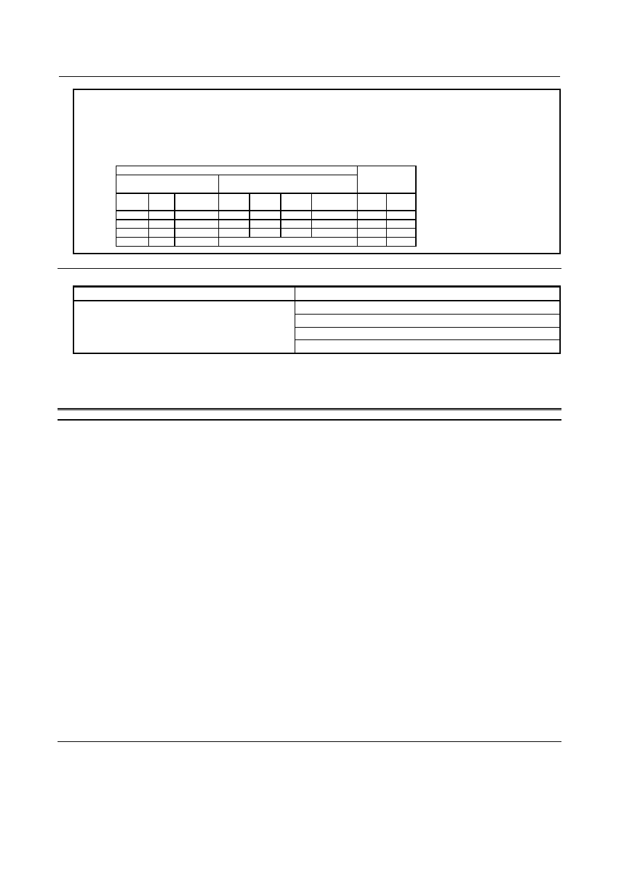
13 For a serial spindle, carefully check the gear count selection statuses of 
clutch/gear signals (CTH1, CTH2) and gear selection signals (GR3O, GR2O, GR1O 
(type M)/GR1, GR2(type T). The spindle speed fluctuation detection function does 
not normally work if the gear count statuses of the two types of signals are different.   


CNC system 

Serial spindle 

side 

Lathe system


Machining center system 

Machining center system 

GR2 

GR1 

Selected 

gear 

GR3

O


GR2

O


GR1

O


Selected 

gear 

CTH1 

CTH2 

1st stage 

1st stage 

2nd stage 

2nd stage 

3rd stage 

3rd stage 

4th stage 


Reference item 

Manual name 

Item name 

CONNECTION MANUAL (FUNCTION) 
(This manual) 

Path spindle control 
Spindle speed control 
Spindle output control by the PMC 
Multi-spindle control 

FANUC AC SPINDLE MOTOR 

α

i

 series PARAMETER MANUAL (B-65280EN) 


10.20 

SPINDLE CONTROL WITH SERVO MOTOR 

Overview 

Servo motors can be controlled by spindle functions like spindle rotation commands or rigid tapping. 
(1)  Spindle control with servo motor 

Rotation commands (S command) can be used to control the speed of spindles by regarding servo 
motors as spindles (live tools). No reference position return is necessary to switch between rotation 
and positioning commands. 

(2)  Spindle indexing 

There are two  types of spindle indexing. The first type allows the next-block command to be 
executed before spindle indexing is finished. The second type allows the next block to be executed 
only after spindle indexing is completed. 
With the first type, it is possible to issue commands to axes other than the axis for which a spindle 
indexing command has been issued, before the next command is issued to the axis. The next 
command can be issued only after it is confirmed that spindle indexing is completed. Using this 
function can reduce the wait time. In addition, an axis can be stopped at a specified point by issuing 
a spindle indexing command to the axis when the spindle is rotating. 

(3)  Rigid tapping with servo motor 

Rigid tapping can be carried out by regarding a servo motor as a rotation axis. 

(4)  Threading, feed per revolution, and constant surface speed control 

Threading, feed per revolution, and constant surface speed control can be carried out by regarding a 
servo motor as a spindle. 

(5)  Spindle output control with PMC 

Spindle output control with PMC can be carried out by regarding a servo motor as a spindle 
controlled axis. 


Notes 

(1)  Enable the spindle serial output (bit 5 (SSN) of parameter No,8133 is 0) and multi-spindle control 

(bit 3 (MSP) of parameter No,8133 is 1). 


If this function is used under the conditions below, the multi-spindle control option is not enabled. 

Two or more spindles are not used on any path. 

B-64693EN-1/01


10. SPINDLE SPEED FUNCTION


- 1787 - 

The spindle gear type is T. 

No G code (G96.1, G96.2, G96.3, or G96.4) commands are used. 

Spindle indexing is not used. 

(2)  This function handles a servo motor used as a spindle controlled axis as one of controlled spindles 

and one of controlled axes. 

(3)  When carrying out rigid tapping with servo motor, enable the rigid tapping  (bit 3 (NRG) of 

parameter No,8135 is 0) and the canned cycle (bit 4 (NCD) of parameter No,8137 is 0). 

(4)  When carrying out constant surface speed control, enable the constant surface speed control  (bit  0 

(SSC) of parameter No,8133 is 1). 
 

Spindle motors and supported functions 

Spindle 

Function 

Conventional 

spindle control 

Spindle control with servo motor 

Threading/feed per revolution 

○ 

○ 

Polygon machining (T series) 

○ 

×(*1) 

Spindle speed fluctuation detection 

○ 

× 

Spindle synchronous control 

○ 

× 

Spindle simple synchronous control 

○ 

× 

Polygon machining with two spindles 

○ 

× 

Spindle orientation 

Multi-point orientation 

Spindle output switching 

○ 

× 

Inter-path spindle control 

○ 

○ 

Constant surface speed control 

○ 

○ 

Multi-spindle control 

○ 

○ 

Rigid tapping 

○ 

○ 

Spindle output control with PMC 

○ 

○ 

Actual spindle speed output (T series) 

○ 

○ 

Spindle indexing 

× 

○ 


NOTE 

Servo motor can be used as 

tool rotation axis.

 (*1) 


10.20.1 

Spindle Control with Servo Motor 

Specification 

  - 

Command with a program 

This function supports two modes; SV speed control mode (a spindle rotation command (S command) is 
enabled for the servo motor-controlled rotation axis) and position control mode (ordinary positioning is 
enabled). Controlling servo motor rotation requires  issuing an SV speed control mode ON command 
(G96.4). Once the command is issued, the S command for the servo motor remains enabled until the mode 
is canceled. No positioning command is usable if the SV speed control mode is ON. 
Performing positioning requires canceling the SV speed control mode.  Canceling the SV speed control 
mode (setting the position control mode to ON) requires issuing a spindle indexing command (G96.1 or 
G96.2). In the position control mode, the S command is disabled as  in the ordinary servo axis state. 
However, information about the S command is preserved. So, when the SV speed control mode becomes 
ON, the motor starts rotating at the speed already specified. 
 

  - 

Command with a signal 

The SV speed control mode signal <Gn521> can also be used to specify whether to turn ON or OFF the 
SV speed control mode. 
If the SV speed control mode is turned ON using the signal and then  OFF using a program command, 
turning it ON again requires re-entering the signal or re-issuing the G96.4 command. 

10. SPINDLE SPEED FUNCTION


B-64693EN-1/01


- 1788 - 

The  SV speed control mode in-progress signal <Fn521> can be used  to check whether the SV speed 
control mode is in effect. 
Turning the SV speed control mode signal OFF during rotation performs spindle indexing and then turns 
the SV speed control mode OFF. Spindle indexing is executed with R0 (absolute position 0). 
Specify an M code not involved in buffering as an M code to be used as a command for switching the SV 
speed control mode (parameters Nos. 3411 to 3420 and 11290 to 11299). 
 

Format 

G96.4 P_ ; 

SV speed control mode ON


M03 (M04) S_ P_ ; 

Rotation command


S: Spindle speed [min

-1

] (numeric value of up to five digits) 

P: Spindle selection with multi-spindle control 

 
Using G96.4 and a spindle selection command P can turn the SV speed control mode ON for each axis 
separately. Likewise, using a spindle indexing command (G96.1/G96.2) and a spindle selection command 
P can cancel the SV speed control mode, that is, turn on the position control mode ON, for each axis 
separately. 
To specify “G96.4 P_ ;”, use an independent block. 
However, it is possible to specify "G96.4 P_ S_ ;". 
 

Explanation 

  - 

Command 

(1)  Spindle speed command output 

Set up the spindle speed command in the same way as for the ordinary speed command (S 
command). However, turn the SV speed control mode ON before issuing the rotation command (S 
command). When performing positioning, cancel the SV speed control mode, and select the position 
control mode. 
The sequence by the following input signals is unnecessary. 
 

*ESPA, MRDYA, and SFRA 

(2)  Condition for stopping spindle speed output 

Commands once output to a spindle become 0 if *SSTP becomes  0 or if a command (such as S0) 
that makes the spindle speed command output 0 is issued. Also, issuing a spindle indexing command 
(G96.1/G96.2) makes the spindle speed command  output 0. In addition, an emergency stop 
condition and servo alarm bring the spindle to a stop. 
With M05, the CNC does not make the command output to the spindle 0. 

(3)  Stopping rotation by spindle indexing 

Issuing a command that specifies a position enables the rotating axis to stop at the specified position. 
For details, see Subsection of "Spindle Indexing Function." 

(4)  Maximum speed 

The maximum speed that can be specified is usually 2777 min

-1

However, setting bit 3 (IRC) of parameter No. 1408 to 1 may be able to increase the limit to about 
27770 min

-1

 depending on the performance of the related motor and detector. (when IS-B is used.) 


Depending on the increment system, the maximum speed is as below. 


Increment system 

Bit 7 (IESP) of parameter No. 1013 = 0 

Bit 7 (IESP) of parameter No. 1013 = 1 

IS-B 

27750min

-1


27750min

-1


IS-C 

2777min

-1


27750min

-1


It is assumed that bit 3 (IRC) of parameter No. 1408 is set to 1 in all cases. 
 

B-64693EN-1/01


10. SPINDLE SPEED FUNCTION


- 1789 - 

  Example command for switching between rotation control and position control 

Spindle name 

Spindle select P code (parameter No. 3781) 

Servo motor axis address 

S1 

P1 


Command with a program (SV speed control mode in-progress signal (Fn521)) 

Program command 

SV speed control mode ON/OFF 

Operation 

G96.4 P1 ; 

ON (SV speed control mode in-progress 

signal (C) =1) 

SV speed control mode ON (C). 

M03 S100 P1 ; 

ON 

The servo motor rotation axis C rotates in the 

normal direction at 100 [min

-1

]. 

G96.1 P1 R0 ; 

OFF (SV speed control mode in-progress 

signal (C) = 0) 

The servo motor rotation axis C stops at C = 

0 (spindle indexing). 

G00 C180.0 ; 

OFF (SV speed control mode in-progress 

signal (C) = 0) 

Positioning at C = 180 degrees. 

M03 S200 P1 ; 

OFF (SV speed control mode in-progress 

signal (C) = 0) 

M03 S200 is stored without causing the servo 

motor to rotate. 

G96.4 P1 ; 

ON (SV speed control mode in-progress 

signal (C) = 1) 

The servo motor rotation axis C rotates in the 

normal direction at 200[min

-1

]. 

SV speed control mode ON (C). 


Signal-controlled mode switching 

Program command 

SV speed control mode ON/OFF 

Operation 

M15 ; 

ON (SV speed control mode in-progress 

signal (C) = 1) 

SV speed control mode is turned ON (C) with 

M code. 

M03 S100 P1 ; 

ON (SV speed control mode in-progress 

signal (C) =1) 

Servo motor rotation axis C rotates in normal 

direction at 100 [min

-1

]. 

G96.1 P1 R0 ; 

OFF (SV speed control mode in-progress 

signal (C)=0) 

Servo motor rotation axis C stops at C = 0 

(spindle indexing). 

G00 C180. ; 

OFF (SV speed control mode in-progress 

signal (C)=0) 

Positioning at C = 180 degrees. 

M15 ; 

ON (SV speed control mode in-progress 

signal (C)=1) 

SV speed control mode is turned ON (C) with 

M code. 

M03 S100 P1 ; 

ON 

Servo motor rotation axis C rotates in normal 

direction at 100 [min

-1

]. 


  - 

Multi-spindle control and commands from another path 

Controlling the rotation of a spindle in a path that has another spindle (such as a servo motor used as a 
live tool) requires the multi-spindle control. The path spindle control function can handle commands from 
another path. The address P-based spindle select function for multi-spindle control can be used to select 
spindles in another path. 
Example of program commands are as follows. 
Example 1: (Spindle selection with address P) 
Bit 3 (MPP) of parameter No. 3703 = 1: A spindle is selected with address P. 
 

Spindle configuration (S1 = first spindle and S2 = second spindle) 

Path 1 

Path 2 

S1 (spindle axis) 

S3 (spindle axis) 

S2 (servo axis) 

S4 (servo axis) 


Setting address P for spindle selection in multi-spindle control 

Parameter 

Path 1 

Path 2 

3781 

11 (S1) 

21 (S3) 

12 (S2) 

22 (S4) 

10. SPINDLE SPEED FUNCTION


B-64693EN-1/01


- 1790 - 


Program example 

Command issuing path 

Program 

Operation 

M03 S1000 P12 ; 

S2 rotates in normal direction at 1000 min

-1

M03 S1500 P22 ; 

S4 rotates in normal direction at 1500 min

-1

M04 S1500 P11 ; 

S1 rotates in reverse direction at 1500 min

-1


  - 

Operation (automatic/manual) of spindle control with servo motor axis 

Once a spindle control with servo motor axis has returned to its reference position, it can operate in the 
same manner as in the  ordinary servo axis or spindle rotation control mode. To operate the a spindle 
control with servo motor axis manually, keep the SV speed control mode OFF. 
 

  - 

Acceleration/deceleration (time constant) 

It is possible to change the spindle acceleration/deceleration specified in a rotation command according to 
the speed of the spindle. 
Acceleration/deceleration can be switched at two points of speed, using parameters S0 and S1 (switching 
speed). In addition,  parameters Aa, Ab, and Ac are available to set up three  acceleration/deceleration 
spans. 


Rotation 
speed (min

-1

S

0


Time (s)


S

1


S


A

a


A

b


A

c


S

0


Setting of parameter No. 11020 (acceleration/deceleration is switched at rotation speed S0 
(min

-1

)). 

S

1


Setting of parameter No. 11021 (acceleration/deceleration is switched at rotation speed S1 
(min

-1

)). 

Specified rotation speed (min

-1

). 

Aa 

Setting of parameter No. 11030 (acceleration/deceleration (min

-1

/s) used between rotation speeds 

0 and S0). 

Ab 

Setting of parameter No. 11031 (acceleration/deceleration (min

-1

/s) used between rotation speeds 

S0 and S1). 

Ac 

Setting of parameter No. 11032 (acceleration/deceleration (min

-1

/s) used between rotation speeds 

S1 and motor’s maximum). 

 
Determine the setting of each parameter according to the torque characteristic of the motor. 
 

  - 

Acceleration/deceleration after interpolation 

Acceleration/deceleration  after interpolation  is available in the SV  speed control mode. Bit 1 (TCR) of 
parameter No. 11001 can be used to select a time constant type, that is, parameter No. 1622 
(Time constant of acceleration/deceleration in cutting feed for each axis) or parameter No. 11016 (Time 
constant of acceleration/ deceleration in SV speed control mode for each axis). 
 

  - 

Direction of rotation 

It is possible to change the polarity of the spindle speed output voltage, using bits 6 (CWM) and 7 (TCM) 
of parameter No. 3706. 
It is also possible to reverse the direction of spindle rotation, using the SV reverse signal <Gn523>. 
These functions are usable in the rotation mode and during rigid  tapping. Changing the signal to 1/0 
during rotation causes the spindle to decelerate, reverse, and then accelerate. 

B-64693EN-1/01


10. SPINDLE SPEED FUNCTION


- 1791 - 

SV reverse signal ON 


Rotation 
speed (min

-1

-S

0


Time (sec)


S

1


A

a


A

b


A

c


-S

1


-S


S

0


A

b


A

c


A

a


0


  - 

Reference position return 

Before issuing the first command, be sure to make a reference position return. 
 

  - 

Display 

Bit 3 (NDF) of parameter No. 3115 can be used to specify whether to display the actual speed. In addition, 
bits 0 (NDP) and 1 (NDA) of parameter No. 3115 can be used to specify whether to display, respectively, 
the current position and the remaining amount of movement. 
 

  - 

Setting of a rotation axis with a servo motor 

(1)  Axis setting 

For the servo axis number of the axis to be set as a rotation axis with a servo motor (parameter No. 
1023), set a value as a servo  motor as usual. Specify which servo motor to use as a spindle 
controlled  axis, using bit 7 (SRV) of parameter No. 11000. Specify which  spindle to use as the 
spindle controlled axis with the servo motor, by setting the spindle number in parameter No. 11010. 
For the selected spindle, reset the spindle amplifier number (parameter No. 3717) to 0. 
In multi-spindle control, set bit 3 (MPP) of parameter No. 3703 to  1 to specify that program 
commands be used to select a spindle. 
Also set parameter No. 3781 with the P code for selecting a spindle. 

(2)  Using a command to specify a spindle speed requires adjusting the following parameters. 

Parameter No. 11013: 

Positioning deviation limit in movement 

Parameter No. 11014: 

Positioning deviation limit in the stop state 

Parameter No. 11015: 

Maximum motor speed 

(3)  Rotation axis setting 

Using bits 0 (ROTx) and 1 (ROSx) of parameter No. 1006, select rotation axis type A. 
Using the rollover function, round the absolute coordinate values  to be displayed to an amount of 
movement per rotation specified in parameter No. 1260 in order to prevent rotation axis coordinate 
overflow. Also round the relative coordinate values to be displayed to an amount of movement per 
rotation by setting bit 2 (RRLx) of parameter No. 1008 to 1. 
The rollover function is enabled by setting bit 0 (ROAx) of parameter No. 1008 to 1 (for the rotation 
axis). 

(4)  Extension of maximum speed 

When using spindle control with servo motor, set 1 to bit 3 (FEX) of parameter No.8003. 


  - 

Example of parameter setting 

The following examples show typical parameter settings. These typical parameter settings should be used 
unless otherwise stated. 
(1)  Spindle controlled axis setting 

Let the fourth axis of the CNC be the C axis. Assuming that  the fourth axis is connected to the 
second spindle, let us use the second spindle as a spindle controlled axis (servo motor). 
No.11000#7 (C) = 1 

10. SPINDLE SPEED FUNCTION


B-64693EN-1/01


- 1792 - 

No.11010 (C) = 2 (a spindle number is specified for a  controlled axis assigned to the spindle 

controlled axis.) 

(Set up No. 3717 (S2) = 0.) 

Given below are the least command increment, detection unit, and the amount of movement per 
rotation for the C axis. 

  Least command increment = 

DMR

CMR

L

×

×


  Detection unit = 

DMR

L

CMR

×

=

increment


command

Least 


  Amount of movement per tool axis rotation = 

increment


command

Least 

360


where 

L: 

Amount of tool movement per motor rotation (360 × speed increment ratio) [deg] 


For example, if the servo motor is connected directly to the spindle (live  tool), L = 360.  For 
example, if the speed must be increased by twice, L = 720. 

Q:  Number of pulses per pulse coder rotation 

(For the serial pulse coder, Q = 1000000.) 
The least command increment mentioned above is specific to the  C axis and is determined 
independently of bits 0 (IS-A) and 1 (IS-C) of parameter No 1013. 
Reset both bits 0 (IS-A) and (IS-C) of parameter No 1013 to 0 to select IS-B. 
If the servo motor is connected directly to the spindle (live tool): 

  Least command increment= 

001

.

0

100

36

1000000

1

360

=

×

×

  [deg] 

  Detection unit = 0.001 [deg] 
  Amount of movement per tool axis rotation =360.0 [deg] 


So, the required parameter setting must be: 
    Parameter No. 11011 (C) = 360.000 (amount of movement per spindle controlled axis rotation) 
In addition, the acceleration/deceleration values for rotation control must be specified in parameters 
Nos. 11020 to 11032. 


Let us assume that the axis parameters be specified for the fourth axis, as follows: 

(2)  Servo parameter setting 

Let us assume: CMR = 1 and DMR = 36/100 
(The capacity of the reference counter will be 360000.) 
  No.1820 (C) = 2        (CMR) 
  No.1821 (C) = 360000      (Reference counter capacity) 
  No.2084 (C) = 36       (DMR numerator) 
  No.2085 (C) = 100      (DMR denominator) 
If the tool axis-to-motor gear ratio is 1:1: 
  No.11015(C) = 5000      (Maximum motor speed) 
  No.3741(S2) = 5000      (Maximum speed for gear 1) 
For the other servo parameters, use the respective typical settings. 

(3)  Full closed system setting 
 

When using spindle control in a full closed system, set bit 1 (FSR) of parameter No. 11000 to 1. 


B-64693EN-1/01


10. SPINDLE SPEED FUNCTION


- 1793 - 

Signal 

SV speed control mode signals SRVON1 to SRVON8<Gn521> 

  [Classification]  Input signal 
 

[Function]  These signal switch the respective axes to the SV speed control mode. 


[Operation]  Setting these signals to 1 cause the respective axes to enter the SV speed control mode. 

Resetting these signals to 0 cause the respective axes to exit the SV speed control mode. 
Resetting the signals to 0 during axis rotation causes the respective axes to start spindle 
indexing, to stop at the origin (R0), and to exit the SV rotation mode. 
 

NOTE 

1  Even if these signals are 1, the spindle control function remains 

disabled when a program command turns the SV speed control 
mode OFF (the SV speed control mode in-progress signal Fn521 
becomes 0). To enable it, re-set these signals to 1. 

2  Specify an M code not involved in buffering as an M code to be 

used as a command for switching the SV speed control mode 
(parameters Nos. 3411 to 3420 and 11290 to 11299). 


SV reverse signals SVRVS1 to SVRVS8<Gn523> 

  [Classification]  Input signal 
 

[Function]  These signals cause the respective axes to reverse their rotation direction in the SV speed 

control mode. 


[Operation]  Setting these signals to 1 cause the respective axes to reverse their rotation direction. 

R

esetting these signals to 0 cause the respective axes to resume  their normal rotation 

direction

.


NOTE 


These signals are effective even in rigid tapping. 


SV speed control mode in-progress signals SVREV1 to SVREV8<Fn521> 

  [Classification]  Output signal 
 

[Function]  These signals inform that the respective axes are in the SV speed control mode. 


[Output cond.]  These signals are 1 if: 

The respective axes are in the SV speed control mode. 

These signals are 0 if: 

The respective axes are in the SV speed control mode, or 

The respective axes are in the position control mode. 


  SV speed control start sequence 

SV speed control cancellation sequence 

SV speed control start 

M code command(*) 


SV speed cancellation 

M code command (*) 


SV speed control mode   

signals SRVONx 


SV speed control mode   

signals SRVONx 


SV speed control mode   

in-progress signals SVREVx 


SV speed control mode   

in-progress signals SVREVx 


End signal FIN   


End signal FIN 


Strobe signal MF   


Strobe signal MF 


  (*)


Specify an M code not involved in buffering as an M code to be used as a command for switching the SV speed control mode. 


Content      ..     227      228      229      230     ..