FANUC Series 0i-MODEL F Plus. CONNECTION MANUAL (FUNCTION) - page 219
 

  Index      Manuals     FANUC Series 0i-MODEL F Plus. CONNECTION MANUAL (FUNCTION) B-64693EN-1/01


Search            copyright infringement  


Content      ..     217      218      219      220     ..


FANUC Series 0i-MODEL F Plus. CONNECTION MANUAL (FUNCTION) - page 219


10. SPINDLE SPEED FUNCTION


B-64693EN-1/01


- 1706 - 

5213 


Return in peck rigid tapping cycle 


[Input type]  Setting input 


[Data type]  Real path 


[Unit of data]  mm, inch (input unit) 

[Min. unit of data]  Depend on the increment system of the drilling axis 
[Valid data range]  0 or positive 9 digit of minimum unit of data (refer to the standard parameter setting table 

(B)) 
(When the increment system is IS-B, 0.0 to +999999.999) 
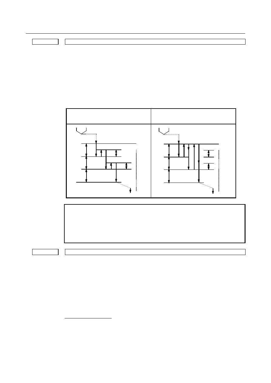
This parameter sets the return or clearance in the peck tapping cycle. 
If the setting value is negative value, it is treated as absolute value. 


When the bit 5 (PCP) of parameter No. 5200 is   
set to 0. (High speed peck tapping cycle) 

When the bit 5 (PCP) of parameter No. 5200 is   
set to 1. (Peck tapping cycle) 

q : Depth of cut 
d : Return value 

R point 

Z point 

q : Depth of cut 
d : Clearance value 

R point 

Z point 


NOTE 


CNC reads a setting value of parameter No.5213 when a block of 
peck rigid tapping cycle is read (buffered). If a setting value of 
parameter No.5213 is changed during automatic operation, a 
setting value has to be changed when buffering is prevented by M 
code preventing buffering and so forth. 


5214 


Setting of an allowable rigid tapping synchronization error range 


[Input type]  Parameter input 


[Data type]  2-word spindle 


[Unit of data]  Detection unit 

[Valid data range]  0 to 99999999 

This parameter sets an allowable synchronization error range in rigid tapping. 
If a synchronous error range exceeding the setting of this parameter is detected, the alarm 
SP0741, “RIGID TAP ALARM : EXCESS ERROR” is issued. When 0 is set in this 
parameter, no synchronization error check is made. 
 
For Smart rigid tapping 
Synchronization error check is always executed in Smart rigid tapping. In regard to 
spindle using Smart rigid tapping, the setting value 0 is treated as 400. The standard 
setting value is 0, but change it if you need. 
 

B-64693EN-1/01


10. SPINDLE SPEED FUNCTION


- 1707 - 

5221 


Number of gear teeth on the spindle side in rigid tapping (first gear) 


5222 


Number of gear teeth on the spindle side in rigid tapping (second gear) 


5223 


Number of gear teeth on the spindle side in rigid tapping (third gear) 


5224 


Number of gear teeth on the spindle side in rigid tapping (fourth gear) 


[Input type]  Parameter input 


[Data type]  Word spindle 

[Valid data range]  1 to 32767 

Each of these parameters is used to set the number of gear teeth on the spindle side for 
each gear in rigid tapping. 
 

NOTE 


When a position coder is attached to the spindle, set the same value 
for all of parameters Nos. 5221 to 5224. 


5231 


Number of gear teeth on the position coder side in rigid tapping (first gear) 


5232 


Number of gear teeth on the position coder side in rigid tapping (second gear) 


5233 


Number of gear teeth on the position coder side in rigid tapping (third gear) 


5234 


Number of gear teeth on the position coder side in rigid tapping (fourth gear) 


[Input type]  Parameter input 


[Data type]  Word spindle 

[Valid data range]  1 to 32767 

Each of these parameters is used to set the number of gear teeth on the position coder side 
for each gear in rigid tapping. 
 

NOTE 


When a position coder is attached to the spindle, set the same value 
for all of parameters Nos. 5231 to 5234. 


5241 


Maximum spindle speed in rigid tapping (first gear) 


5242 


Maximum spindle speed in rigid tapping (second gear) 


5243 


Maximum spindle speed in rigid tapping (third gear) 


5244 


Maximum spindle speed in rigid tapping (fourth gear) 


[Input type]  Parameter input 


[Data type]  2-word spindle 


[Unit of data]  min

-1


[Valid data range]  0 to 9999 

Spindle position coder gear ratio 
1 : 1    0 to 7400 
1 : 2    0 to 9999 
1 : 4    0 to 9999 
1 : 8    0 to 9999 

10. SPINDLE SPEED FUNCTION


B-64693EN-1/01


- 1708 - 

Each of these parameters is used to set a maximum spindle speed for each gear in rigid 
tapping. 
 
Set the same value for both parameters Nos. 5241 and 5243 for a one-stage gear system. 
For a two-stage gear system, set the same value as set in parameter No. 5242 in parameter 
No. 5243. Otherwise, alarm PS0200, “ILLEGAL S CODE COMMAND” will be issued. 
This applies to the machining center system. 
 

5261 


Time constant for acceleration/deceleration in rigid tapping for each gear (first gear) 


5262 


Time constant for acceleration/deceleration in rigid tapping for each gear (second gear) 


5263 


Time constant for acceleration/deceleration in rigid tapping for each gear (third gear) 


5264 


Time constant for acceleration/deceleration in rigid tapping for each gear (fourth gear) 


[Input type]  Parameter input 


[Data type]  Word spindle 


[Unit of data]  msec 

[Valid data range]  0 to 4000 

Each of these parameters is used to set a linear acceleration/ deceleration time constant 
for the spindle of each gear and the tapping axis in rigid tapping. 
Set the period required to reach each maximum spindle speed (parameters Nos. 5241 to 
5244).   
The set time constant, multiplied by the ratio of a specified S value to a maximum spindle 
speed, is actually used as a time constant. 
For bell-shaped acceleration/deceleration, set a time constant for a linear portion. 
 

5271 


Time constant for acceleration/deceleration in rigid tapping extraction (first gear) 


5272 


Time constant for acceleration/deceleration in rigid tapping extraction (second gear) 


5273 


Time constant for acceleration/deceleration in rigid tapping extraction (third gear) 


5274 


Time constant for acceleration/deceleration in rigid tapping extraction (fourth gear) 


[Input type]  Parameter input 


[Data type]  Word spindle 


[Unit of data]  msec 

[Valid data range]  0 to 4000 

Each of these parameters is used to set a linear acceleration/ deceleration time constant 
for the spindle of each gear and tapping axis in extraction operation during rigid tapping. 
For bell-shaped acceleration/deceleration, set a time constant for a linear portion. 
 

NOTE 


These parameters are enabled when the parameter TDR (bit 2 of 
parameter No. 5201) is set to 1. 


5280 


Position control loop gain for the spindle and tapping axis in rigid tapping (common to gears) 


5281 


Position control loop gain for the spindle and tapping axis in rigid tapping (first gear) 


5282 


Position control loop gain for the spindle and tapping axis in rigid tapping (second gear) 


5283 


Position control loop gain for the spindle and tapping axis in rigid tapping (third gear) 


B-64693EN-1/01


10. SPINDLE SPEED FUNCTION


- 1709 - 

5284 


Position control loop gain for the spindle and tapping axis in rigid tapping (fourth gear) 


[Input type]  Parameter input 


[Data type]  Word spindle 


[Unit of data]  0.01/sec 

[Valid data range]  1 to 9999 

Each of these parameters is used to set a position control loop gain for the spindle and 
tapping axis in rigid tapping. These parameters significantly affect the precision of 
threading. Optimize these parameters as well as the loop gain multipliers by conducting a 
cutting test. 
 

NOTE 


To use a varied loop gain on a gear-by-gear basis, set parameter 
No. 5280 to 0, and set a loop gain for each gear in parameters 
Nos. 5281 to 5284. The specification of a loop gain on a 
gear-by-gear basis is disabled if parameter No. 5280 is set to a 
value other than 0. In such a case, the value set in parameter No. 
5280 is used as a loop gain that is common to all the gears. 


5291 


Loop gain multiplier for the spindle in rigid tapping (first gear) 


5292 


Loop gain multiplier for the spindle in rigid tapping (second gear) 


5293 


Loop gain multiplier for the spindle in rigid tapping (third gear) 


5294 


Loop gain multiplier for the spindle in rigid tapping (fourth gear) 


[Input type]  Parameter input 


[Data type]  Word spindle 

[Valid data range]  1 to 32767 

Each of these parameters  is used to set a loop gain multiplier for the spindle in rigid 
tapping each gear. 
These parameters significantly affect the precision of threading. Optimize these 
parameters as well as the loop gains by conducting a cutting test. 
Loop gain multiplier GC is obtained from the following equation: 

L

SP

PLS

E

PC

GC

×

×

×

×

×

=

360

2048000


PLS

  Number of pulses output from the position coder (pulses/rev)   

SP

  Number of gear teeth on the spindle side 

PC

  Number of gear teeth on the position coder side 

Specified voltage (V) for turning the spindle motor at 1000 min

-1


L


Angular displacement of the spindle (degrees) per spindle motor rotation 


[Example]  For the spindle motor and gear ratio given below, GC is calculated as follows: 

1100

360

1

4096

2

.

2

1

360

2048000

=

×

×

×

×

×

=

GC


PLS

  = 4096 pulse/rev 

SP 

= 1 

PC 

= 1 

= 2.2 V 

L


= 360 deg 

(Note)  On the assumption that the spindle motor used turns at 4500 min

-1 

at 10 V, 2.2 V 

is required to turn the spindle motor at 1000 min

-1


10. SPINDLE SPEED FUNCTION


B-64693EN-1/01


- 1710 - 

NOTE 


These parameters are used for analog spindles. 


5300 


Tapping axis in-position width in rigid tapping (first spindle) 


5302 


Tapping axis in-position width in rigid tapping (second spindle) 


5304 


Tapping axis in-position width in rigid tapping (third spindle) 


5306 


Tapping axis in-position width in rigid tapping (fourth spindle) 


[Input type]  Parameter input 


[Data type]  Word axis 


[Unit of data]  Detection unit 

[Valid data range]  0 to 32767 

This parameter sets a tapping axis in-position width when rigid tapping is performed 
using the each spindle. 
If the setting value is negative value, in-position check is not completed. 
 

5301 


Spindle in-position width in rigid tapping 


[Input type]  Parameter input 


[Data type]  Word spindle 


[Unit of data]  Detection unit 

[Valid data range]  0 to 32767 

This parameter are used to set spindle in-position width in rigid tapping. 
If the setting value is negative value, in-position check is not completed. 
 

NOTE 


If an excessively large value is specified, the threading precision 
will deteriorate. 


5310 


Positional deviation limit imposed during tapping axis movement in rigid tapping (first spindle) 


5350 


Positional deviation limit imposed during tapping axis movement in rigid tapping (second spindle) 


5354 


Positional deviation limit imposed during tapping axis movement in rigid tapping (third spindle) 


5358 


Positional deviation limit imposed during tapping axis movement in rigid tapping (fourth spindle) 


[Input type]  Parameter input 


[Data type]  2-word axis 


[Unit of data]  Detection unit 

[Valid data range]  0 to 99999999 

This parameter sets a positional deviation limit imposed during tapping axis movement in 
rigid tapping using the each spindle. 
 

5311 


Limit value of spindle positioning deviation during movement in rigid tapping 


[Input type]  Parameter input 


[Data type]  2-word spindle 


[Unit of data]  Detection unit 

[Valid data range]  0 to 99999999 

B-64693EN-1/01


10. SPINDLE SPEED FUNCTION


- 1711 - 

This parameter sets the limit value of a spindle positioning deviation during movement in 
rigid tapping. 
Find a value to be set from the following expression: 

PC

G

C

SP

PLS

S

value

Setting

×

×

×

×

×

×

=

60

100


S

    Maximum spindle speed in rigid tapping (min

-1

(Setting value of parameters Nos. 5241 and to 5244) 

PLS

  Number of pulses output from the position coder (pulses/rev) 

SP

  Number of gear teeth on the spindle side 

PC

  Number of gear teeth on the position coder side 

G


Loop gain in the rigid tapping (0.01sec

-1

(Setting value of parameters Nos. 5281 and to 5284) 

C


Coefficient 1.5 


[Calculation example] 

= 3600 

PLS 

= 4096 

SP 

= 10 

PC 

= 20 

= 3000 

= 1.5 


6144

20

3000

60

5

.

1

10

100

4096

3600

=

×

×

×

×

×

×

=

value

Setting


5312 


Positional deviation limit imposed while the tapping axis is stopped in rigid tapping (first spindle) 


5352 


Positional deviation limit imposed while the tapping axis is stopped in rigid tapping (second spindle) 


5356 


Positional deviation limit imposed while the tapping axis is stopped in rigid tapping (third spindle) 


5360 


Positional deviation limit imposed while the tapping axis is stopped in rigid tapping (fourth spindle) 


[Input type]  Parameter input 


[Data type]  Word axis 


[Unit of data]  Detection unit 

[Valid data range]  0 to 32767 

This parameter sets a positional deviation limit imposed while the tapping axis is stopped 
in rigid tapping using the each spindle. 
 

5313 


Positional deviation limit imposed while the spindle is stopped in rigid tapping 


[Input type]  Parameter input 


[Data type]  2-word spindle 


[Unit of data]  Detection unit 

[Valid data range]  0 to 99999999 

This parameter is used to set a positional deviation limit imposed while the spindle is 
stopped in rigid tapping. 


 10 : 10 : 20 

SPINDLE   
MOTOR 

Spindle 

Position 
coder 


10. SPINDLE SPEED FUNCTION


B-64693EN-1/01


- 1712 - 


5321 


Spindle backlash in rigid tapping (first-stage gear) 


5322 


Spindle backlash in rigid tapping (second-stage gear) 


5323 


Spindle backlash in rigid tapping (third-stage gear) 


5324 


Spindle backlash in rigid tapping (fourth-stage gear) 


[Input type]  Parameter input 


[Data type]  Word spindle 


[Unit of data]  Detection unit ([detection unit]=[spindle rotation angle per one rotation of position 

coder]/4096 for 

a

i

 position coder) 

[Valid data range]  -9999 to 9999 

Each of these parameters is used to set a spindle backlash in rigid tapping. 
 

5365 


Bell-shaped acceleration/deceleration time constant in rigid tapping (first-stage gear) 


5366 


Bell-shaped acceleration/deceleration time constant in rigid tapping (second-stage gear) 


5367 


Bell-shaped acceleration/deceleration time constant in rigid tapping (third-stage gear) 


5368 


Bell-shaped acceleration/deceleration time constant in rigid tapping (fourth-stage gear) 


[Input type]  Parameter input 


[Data type]  Word spindle 


[Unit of data]  msec 

[Valid data range]  0 to 512 

Each of these parameters is used to set a time constant for a curved portion when 
bell-shaped acceleration/deceleration is selected in rigid tapping. When 0 is set in this 
parameter, linear acceleration/ deceleration is performed. 
 

NOTE 


This parameter is enabled when the bit 5 (RBL) of parameter No. 
5203 is set to 1. 


#7 

#6 

#5 

#4 

#3 

#2 

#1 

#0 

24203 


FHR 


NOTE 


When the parameter is set, the power must be turned off before 
operation is continued. 


[Input type]  Parameter input 


[Data type]  Bit 


#0  FHR

  Position data transmission by FSSB is: 

0: 

Disabled. 

1: 

Enabled. 

NOTE 

1  In addition, it is necessary to set parameter No.24204. 
2  When FSSB high-speed rigid tapping is used, set 1 to this 

parameter. 

B-64693EN-1/01


10. SPINDLE SPEED FUNCTION


- 1713 - 


24204 


The index number of the spindle axis that synchronizes to each servo axis 


NOTE 


When the parameter is set, the power must be turned off before 
operation is continued. 


[Input type]  Parameter input 


[Data type]  Byte axis 

[Valid data range]  0 to the maximum number of spindles 

In FSSB high-speed rigid tapping, set the index number of the spindle axis that 
synchronizes to servo axis.   


NOTE 

1  When the bit 0 (FHR) of parameter No.24203 is 1, this parameter 

is enabled. 

2  Eight or less index numbers of the spindle axis can be set in the 

system. If nine or more index numbers of the spindle axis are set, 
the alarm PW0037, "SV/SP COMBINATION ERROR" is issued. 


24208 


The index number of the spindle axis that synchronizes to each servo axis (2nd set) 


[Input type]  Parameter input 


[Data type]  Byte axis 

[Valid data range]  0 to the maximum number of spindles 
This parameter sets the index number of the spindle synchronizing with the servo axis used in FSSB 

high-speed rigid tapping. Whether to use parameter No.24204 or this parameter can be 
changed by Spindle/Servo axis combination change signal SPSVS<G0518.6>. 


NOTE 

1  This parameter is effective when parameter FHR (No.24203#0)=1. 
2  Eight or less index numbers of the spindle axis can be set in the 

system. If nine or more are set, the alarm (DS0092) "SV/SP 
COMBINATION ERROR" is issued. 


Alarm and message 

Number 

Message 

Description 

PS0200 

ILLEGAL S CODE COMMAND 

(1)  In the rigid tap, an S value was out of range or was not 

specified. The parameters Nos. 5241 to 5243 setting is 
an S value which can be specified for the rigid tapping. 
Correct the parameters or modify the program. 

(2)  Rigid tapping is commanded during constant surface 

speed control. Command rigid tapping after canceling 
constant surface speed control. 

PS0201 

FEEDRATE NOT FOUND IN RIGID 
TAP 

The command F code for a cutting feedrate is a zero. 
If the value of F command is much smaller than that of the S 
command, when a rigid tapping command is specified, this 
alarm is generated. This is because cutting is not possible by 
the lead specified by the program. 

PS0202 

POSITION LSI OVERFLOW 

In the rigid tap, spindle distribution value is too large. 
Decrease spindle speed.   


Content      ..     217      218      219      220     ..