FANUC Series 0i-MODEL F Plus. CONNECTION MANUAL (FUNCTION) - page 140
 

  Index      Manuals     FANUC Series 0i-MODEL F Plus. CONNECTION MANUAL (FUNCTION) B-64693EN-1/01


Search            copyright infringement  


Content      ..     138      139      140      141     ..


FANUC Series 0i-MODEL F Plus. CONNECTION MANUAL (FUNCTION) - page 140


6. INTERPOLATION FUNCTION


B-64693EN-1/01


- 1074 - 

When any of the operations above is set as an operation of linear interpolation type, 
acceleration/deceleration control follows the setting of bit 4 (PRT) of parameter No. 1603. 
 

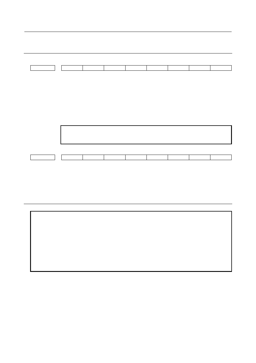
Parameter 


#7 

#6 

#5 

#4 

#3 

#2 

#1 

#0 

1015 


ZRL 


[Input type]  Parameter input 


[Data type]  Bit path 


#4  ZRL

  When a reference position  is  established, the tool  path from the middle point to the 

reference position  and  machine  coordinate  positioning  (G53) in automatic  reference 
position return (G28) or 2nd/3rd/4th reference position return (G30) are based on: 
0: 

Positioning of nonlinear interpolation type 

1: 

Positioning of linear interpolation type 


NOTE 


This parameter is valid when bit 1 (LRP) of parameter No. 1401 is 
set to 1. 


#7 

#6 

#5 

#4 

#3 

#2 

#1 

#0 

1603 


PRT 


[Input type]  Parameter input 


[Data type]  Bit path 


#4  PRT

  For positioning of linear interpolation type: 

0: 

Acceleration/deceleration of acceleration fixed type is used. 

1: 

Acceleration/deceleration of time fixed type is used. 


Note 

NOTE 


Automatic reference position return operation of low-speed type (G28) 


If reference position return operation is not performed for a specified axis even 
once after the power is turned on in automatic reference position return operation 
(G28), a reference position return operation of low-speed type is performed for 
the axis. 
At this time, positioning of non-linear interpolation type is performed. 


For example, if G28X0Y0Z0; is specified when reference position return 
operation is completed for the X-axis and Y-axis, and is not completed for the 
Z-axis, positioning of non-linear interpolation type is performed. 


B-64693EN-1/01


6. INTERPOLATION FUNCTION


- 1075 - 

6.12 

SMOOTH TOLERANCE

+

 CONTROL 

M


Overview 

Smooth tolerance

+

 control is a function that generates smooth machining path within specified tolerance. 

In the case of die mold machining program that consists of small line segments, this function acts as 
smoothing function and makes joints of blocks smooth. As the result, machining surface gets high quality. 
 

Smoothing small line segments 

This function smooths small line segments. If the length of linear blocks is less than the value set at 
parameter No. 19595, those blocks are treated as small line segment blocks, and smooth curves not 
depending on commanded points are generated, which are within tolerance from commanded points. 
Machining gets smoother even if there are small discontinuous blocks in a program. 
Tolerance is set as same value as CAM tolerance which generating small line segments. Tolerance is 
specified by parameters (No.11786, 11787) or NC program (G10.8L4Q_R_). 


Fig. 6.12 (a) Smoothing small line segments 


Command format (In Case of 3-axis Machining) 

G05.1 Q3 Xp0 Yp0 Zp0; 

Smooth tolerance

+

 control mode on 

G10.8 L4 Q_; 

Specify tolerance


G05.1 Q0; 

Smooth tolerance

+

 control mode off 

Xp:  X-axis or an axis parallel to the X-axis 

Yp:  Y-axis or an axis parallel to the Y-axis 

Zp:  Z-axis or an axis parallel to the Z-axis 

Q: 

Tolerance for linear axis on curves 


NOTE


1  Specify G05.1 Q3 alone in a block. 

(To avoid specifying any other G code in the same block) 

2  Unit of “Q” in G10.8 command depends on the increment system of the basic 

axis. 

3  The value of parameter No. 11786 is effective as tolerance between G05.1 Q3 

command and G10.8 L4 command. 


Tolerance


Smoothing 

OFF


Smoothing 

ON


Smoothing tool path 

Polyhedral surface 

Smooth surface 

6. INTERPOLATION FUNCTION


B-64693EN-1/01


- 1076 - 

4  Smooth tolerance

+

 control is disabled when the tolerance for linear axis is set to 

0. 

5  Smooth tolerance

+

 control mode is activated at the start of automatic operation 

by setting bit 0 (CAT) of parameter No. 11785. 


Description of the Function 


- Automatically turning on AI contour control with Smooth tolerance

+

 control 

Specifying G5.1 Q3 also enables Smooth tolerance

+

 control and AI contour control to be turned on at the 

same time. 
The automatic velocity control by AI contour control reduces impacts on the mechanical system. 
 

- Conditions for enabling Smooth tolerance

+

 control 

Smooth tolerance

+

 control is enabled when the following conditions are satisfied. 

In a block that does not satisfy the conditions for enabling it, Smooth tolerance

+

 control is canceled, and it 

is judged 
in the next block whether to perform Smooth tolerance

+

 control again. 

-


The mode is all of the following: 

-


Cutting mode (G64) 

-


Linear interpolation (G01) 

-


Feed per minute (G94, however G98 in G code system A of T series ) 

or Feed per revolution(G95, however G99 in G code system A of T series ) 

-


Constant surface speed control cancel (G97) 

-


Normal direction control cancel (G40.1) 

-


Polar coordinate command cancel (G15) 

-


Polar coordinate interpolation cancel (G13.1) 

-


Polygon turning cancel (G50.2) 

-


The block does not contain a one shot G code command. 

-


The block does not contain MST command. 

-


The block does not suppress look ahead (buffering). 

-


The block contains a move for at least a linear axis. 

-


The block contains a move command for only axes subject to Smooth tolerance

+

 control. 

-


The difference between a radius at the beginning point and a radius at the end point is less than 20μm. 

-


Smooth tolerance

+

 control disable signal STCD <Gn599.2> is “0”. 

-


Block length is less than the value of parameter No. 19595. 


- Interlock 

When an axis for Smooth tolerance

+

  control is interlocked, all axes are interlocked in the block which 

Smooth tolerance

+

 control is enabled, even if the interlocked axis is not commanded in the block. 


- Axis moving signals 

In the block which Smooth tolerance

+

 control is enabled, axis moving signals MV1 to MV8 <Fn102> for 

axes for Smooth tolerance

+

 control are set to one regardless of the movement. 


- Use with other functions 

In the case Smooth tolerance

+

 control is used with the following functions, it controls paths which each 

function is applied. 

-


Cutter compensation and tool nose radius compensation 

-


Tool length compensation 

-


Programmable mirror image 

-


Scaling 

-


Coordinate system rotation 


B-64693EN-1/01


6. INTERPOLATION FUNCTION


- 1077 - 

Use with cutter compensation and tool nose radius compensation 

In case using cutter compensation and tool nose radius compensation, Smooth tolerance

+

  control works 

for paths cutter compensation and tool nose radius compensation applied.   
 

- Status display in the Smooth Tolerance

+

 control mode 

Character string “TOLCON” blinks in the status bar when Smooth tolerance

+

 control mode is enabled.   


Fig. 6.12 (b) Status display in the Smooth Tolerance+ control mode 


6.12.1 

Change Tolerance in Smooth Tolerance

+

 Control Mode 

The tolerance in smooth tolerance

+

 control mode can be changed any time by specifying G10.8 L4. The 

appropriate tolerance can be used which depends on situations in a program. 
 

Format 

Change Tolerance in Smooth Tolerance

+

 Control Mode 

G10.8 L4 Q_ R_; 

Directly specify tolerance


G10.8 L4; 

Use paramter (No.11786, No.11787) as default tolerance


Q: 

Tolerance for linear axis on curves 

R: 

Tolerance for rotary axis on curves 


NOTE


1  Specify G10.8 alone in a block. 

(Avoid specifying any other G code in the same block) 

2  G10.8 L4 is a one-shot G code. 
3  Unit of “Q” and “R” in G10.8 command depends on the increment system of the 

basic axis. 

4  Specifying a negative value to “Q” or “R” causes alarm PS2010, “ILL. COMMAND 

IN TOLERANCE CON.”. 

5  When G10.8 L4 specified not in smooth tolerance

+

 control mode (G05.1 Q3), 

alarm PS0412, “ILLEGAL G CODE” is issued. 

6  The value of parameter No. 11786 and No. 11787 do not change by specifying 

G10.8 L4. 


Example (1) 

Here is an example for changing tolerance in smooth tolerance

+

 control mode. 

 
O0012; 
G28 G91 X0 Y0; 
G05.1 Q3 X0 Y0 Z0; 


(Smooth tolerance

+

 control mode on) 

G10.8 L4 Q0.002; 


(Tolerance is set.) 

G00 G90 X100.0 Y100.0 Z100.0; 
G01 X100.121 Y100.321 F1000; 
X100.121 Y100.321; 


X100.321 Y100.881; 


X100.721 Y101.365; 


Smoothing (Tolerance = 

2μm) 


6. INTERPOLATION FUNCTION


B-64693EN-1/01


- 1078 - 

G10.8 L4 Q0.003; 


(Tolerance is changed.) 

X110.121 Y120.321; 
X110.321 Y120.881; 
X110.721 Y121.365; 


Smoothing (Tolerance = 3μm) 


G05.1 Q0; 


(Smooth tolerance

+

 control mode off) 

M30; 


Signal 

Smooth tolerance

+

 control disable signal STCD <Gn599.2> 

  [Classification]  Input signal 
 

[Function]  Switches Smooth tolerance

+

 control mode on / off. 


[Operation]  When a signal is set to “1”, Smooth tolerance

+

 control is disabled. 

This signal is effective for blocks analyzed after the signal switched. 


Note


1  Do not change this signal in the feed hold stop state. If this signal is 

changed, alarm PS2012 “ILL. OPERATION IN TOLERANCE CON.” 
is issued in restarting operation. 

2  Switching this signal does not mean switching Smooth tolerance

+


control mode immediately. Actual switch takes place when Smooth 
tolerance

+

 control mode can be changed. 


Signal address 


#7 

#6 

#5 

#4 

#3 

#2 

#1 

#0 

Gn599 


STCD 


Parameter 


#7 

#6 

#5 

#4 

#3 

#2 

#1 

#0 

11785 


CAT 


[Input type]  Parameter input 


[Data type]  Bit axis 


#0  CAT

  On start up of automatic operation, smooth tolerance

+

 control is: 

0: 

Ineffective on an axis. 

1: 

Effective on an axis. 


11786 


Smoothing tolerance for linear axis in smooth tolerance

+

 control mode 


[Input type]  Parameter input 


[Data type]  Real path 


2μm


3μm


B-64693EN-1/01


6. INTERPOLATION FUNCTION


- 1079 - 


[Unit of data]  mm, inch (input unit) 

[Min. unit of data]  Depend on the increment system of the reference axis 
[Valid data range]  0 or positive 9 digit of minimum unit of data (refer to the standard parameter setting table 

(B))   
(When the increment system is IS-B, 0.000 to +999999.999) 
Set tolerance for linear axes for curves generated in smooth tolerance

+

  control mode. If 

tolerance  is not specified in tolerance mode, machining path is controlled so that the 
machining accuracy on curves represented by small segment is within the tolerance set to 
this parameter. 
When this parameter is set to 0 or less, the smoothing is not effective. 


11787 


Smoothing tolerance for rotary axis in smooth tolerance

+

 control mode 


[Input type]  Parameter input 


[Data type]  Real path 


[Unit of data]  deg (machine unit) 

[Min. unit of data]  Depend on the increment system of the reference axis 
[Valid data range]  0 or positive 9 digit of minimum unit of data (refer to the standard parameter setting table 

(B))   
(When the increment system is IS-B, 0.000 to +999999.999) 
Set tolerance for rotary axes for curves generated in smooth tolerance

+

  control mode. If 

tolerance is not specified in tolerance mode, machining path is controlled so that the 
machining accuracy on curves represented by small segment is within the tolerance set to 
this parameter. 

When this parameter is set to 0 or less, it operates as 0.05˚ is set. 


#7 

#6 

#5 

#4 

#3 

#2 

#1 

#0 

11790 


SMC 


[Input type]  Parameter input 


[Data type]  Bit path 


#3  SMC

  When smooth tolerance

+

 control is used with macro modal call, smooth tolerance

+

 control 

is, 
0: 

Effective. 

1: 

Disabled. (Temporary disabled while macro modal call is effective) 


11791 


Angle for breaking smoothing in smooth tolerance

+

 control mode 


[Input type]  Parameter input 


[Data type]  Real path 


[Unit of data]  deg 

[Min. unit of data]  Depend on the increment system of the reference axis 
[Valid data range]  0 to 90 

Set the angle to judge if smoothing of smooth tolerance

+

 control is effective or not. 

When this parameter is set to 0, the smoothing is not disabled. 
 

19595 


Maximum block length for small line segments in smooth tolerance

+

 control mode 


[Input type]  Parameter input 


[Data type]  Real path 


[Unit of data]  mm, inch (input unit) 

[Min. unit of data]  Depend on the increment system of the reference axis 

6. INTERPOLATION FUNCTION


B-64693EN-1/01


- 1080 - 

[Valid data range]  0 or positive 9 digit of minimum unit of data (refer to the standard parameter setting table 

(B))   
(When the increment system is IS-B, 0.000 to +999999.999) 
Set maximum block length for regarding a linear block as a small line segment in smooth 
tolerance

+

  control mode. If the block length is less than the value of this parameter, 

smoothing of small line segments is applied to the block. 
When this parameter is set to 0 or less, smoothing is applied to any block. 


19599 


Maximum allowable acceleration rate for the deceleration function   

based on acceleration in smooth tolerance

+

 control mode for each axis 


[Input type]  Parameter input 


[Data type]  Real axis 


[Unit of data]  mm/sec2, inch/sec2, deg/sec2 (machine unit) 

[Min. unit of data]  Depend on the increment system of the applied axis 
[Valid data range]  Refer to the standard parameter setting table (D)   

(When the machine system is metric system, 0.0 to +100000.0. When the machine system 
is inch system, machine, 0.0 to +10000.0.) 
Feedrate is controlled so that acceleration produced by changing the move direction does 
not exceed the value specified to this parameter in smooth tolerance

+

 control mode. 

This parameter is valid for basic 3-axes (the axes that 1, 2, 3 are set in the parameter 
No.1022). This parameter of the other axes is invalid, and not necessary to be set. 
For an axis with 0 set in this parameter, the deceleration function based on acceleration in 
smooth tolerance

+

 control mode is disabled. 

If a different value is set to this parameter for each axis, a feedrate is determined from the 
smallest of the acceleration rates specified for the moving axes. 
 

Diagnosis data 


5000 


The index number of the spindle axis that synchronizes with each servo axis 


[Data Type]  Bit 

TOLERANCE ON 
 
When smooth tolerance

+

 control G5.1 Q3 is specified and all conditions are satisfied, "1" 

is indicated. G5.1 Q3 command turns on AI contour control at the same time. Therefore, 
the AI contour control mode signal AICC<Fn062.0> turns on. 

B-64693EN-1/01


6. INTERPOLATION FUNCTION


- 1081 - 


5006 


Tolerance for linear axes for curves generated in smooth tolerance

+

 control mode 


[Data type]  Real path 


[Unit of data]  mm/inch 

[Valid data range]  0 or positive 9 digit of minimum unit of data 
 

[Meaning]  Tolerance for linear axes for curves generated in smooth tolerance

+

  control mode is 

displayed. 
In the beginning of smooth tolerance

+

 control mode, the value of a parameter No.11786 is 

displayed.   
When the tolerance is changed by G10.8L4, the changed tolerance is displayed. 


5007 


Tolerance for rotary axes for curves generated in smooth tolerance

+

 control mode 


[Data type]  Real path 


[Unit of data]  deg 

[Valid data range]  0 or positive 9 digit of minimum unit of data 
 

[Meaning]  Tolerance for rotary axes for curves generated in smooth tolerance

+

  control mode is 

displayed. 
In the beginning of smooth tolerance

+

 control mode, the value of a parameter No.11787 is 

displayed.   
When the tolerance is changed by G10.8L4, the changed tolerance is displayed. 


Alarm 

Number 

Message 

Description 

PS0412 

ILLEGAL G CODE 

Illegal G code is specified. 
- G10.8L4 is specified not in smooth tolerance

+

 control mode.   

PS2010 

ILL. COMMAND IN TOLERANCE CON.  Illegal command is specified in smooth tolerance

+

 control 

mode. Check the program. 

PS2011 

ILL. PARAMETER   
IN TOLERANCE CON. 

Illegal parameter is set, which is related to smooth tolerance

+


control. Check the parameter settings. 

PS2012 

ILL. OPERATION IN TOLERANCE 
CON. 

Illegal operation is done in smooth tolerance

+

 control mode. 


Content      ..     138      139      140      141     ..