FANUC Series 0i-MODEL F Plus. CONNECTION MANUAL (FUNCTION) - page 138
 

  Index      Manuals     FANUC Series 0i-MODEL F Plus. CONNECTION MANUAL (FUNCTION) B-64693EN-1/01


Search            copyright infringement  


Content      ..     136      137      138      139     ..


FANUC Series 0i-MODEL F Plus. CONNECTION MANUAL (FUNCTION) - page 138


6. INTERPOLATION FUNCTION


B-64693EN-1/01


- 1058 - 

PMC sequence 

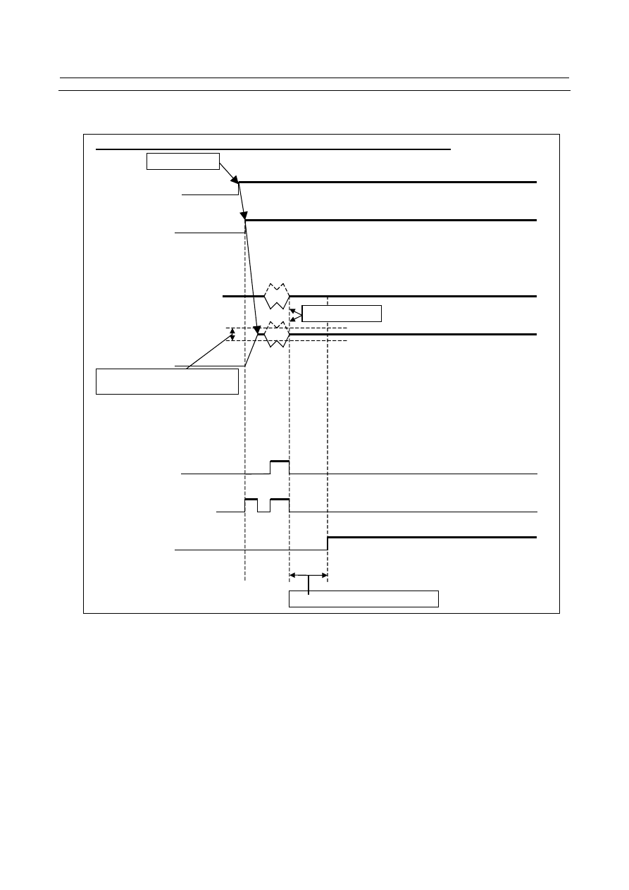
The following shows the signal status time chart when the polygon synchronization mode is on and off. 


  Signal status time chart when the polygon synchronization mode is on 


Polygon sync axis 
rotation control 
 

G51.2 command 

Phase matching 

Steady state checking time (ms) 

Speed deviation level (min

-1

Polygon sync ON 
Polygon sync OFF 
 

Master axis rotation control 

Polygon master axis not 
arrival signal 

Polygon sync axis not arrival 
signal 

PSAR 

Polygon spindle speed 
arrival signal 

PSE1 

PSE2 

Polygon sync under way signal 

PSYN 


Fig. 6.9.2 (b) 


B-64693EN-1/01


6. INTERPOLATION FUNCTION


- 1059 - 


  Signal status time chart when the polygon synchronization mode is off 


Polygon sync axis   
rotation control 

G50.2 command 

Polygon sync ON 
Polygon sync OFF 

Master axis rotation 
signal 

Polygon master axis not 
arrival signal 

Polygon sync axis not 
arrival signal 

PSAR 

Polygon spindle speed 
arrival signal 

PSE1 

PSE2 

Polygon sync under way signal 
PSYN 


Fig. 6.9.2 (c) 

 
When the polygon synchronization mode is started by the G51.2 command, the polygon synchronization 
under way signal PSYN<Fn063.7> is set to “1”. 
Create a PMC sequence during the polygon synchronization mode by checking the polygon 
synchronization under way signal with the PMC ladder. 
 
First, select one method of controlling spindle activation used during the polygon synchronization mode 
from methods A and B. Then create a PMC sequence according to the selected method. 
 

  - 

Method A 

During the polygon synchronization mode, activation of the master axis and polygon synchronization axis 
is automatically turned on. 
During this mode, activation of the spindle is not turned off. 
 
For method A, set bit 7 (PST) of parameter No. 7603 to 0. 
In a PMC sequence, activation of the master axis and polygon synchronization axis must be turned on 
when the polygon synchronization under way signal PSYN<Fn063.7> changes from “0” to “1”. 
 

6. INTERPOLATION FUNCTION


B-64693EN-1/01


- 1060 - 

In addition, while the polygon synchronization under way signal is 1, prevent the activation of the master 
axis and polygon synchronization axis from being turned off by, for example, prohibiting the acceptance 
of spindle stop (for example M05) during normal control. 
 
When the polygon synchronization under way signal PSYN<Fn063.7> changes from “1” to “0”, basically 
turn off activation. 
 
The NC stops at the G51.2 command block for entering the polygon synchronization mode and does not 
proceed to the next block until the spindle speed reaches the polygon synchronization speed. 
 

  - 

Method B 

Even during the polygon synchronization mode, another M code or the like is used to turn on or off 
activation of the spindle. 
Or, even during the polygon synchronization mode, activation of the spindle may be turned off. 
 
For method B, set bit 7 (PST) of parameter No. 7603 to 1. 
This parameter setting enables the polygon spindle stop signal *PLSST<Gn038.0> and makes the NC 
proceed to the next block without waiting for the spindle speed to reach the polygon synchronization 
speed in the G51.2 command block for starting the polygon synchronization mode. 
 
In a PMC sequence, during the polygon synchronization mode (the polygon synchronization under way 
signal PSYN<Fn063.7> is “1”), set the polygon spindle stop signal *PLSST<Gn038.0> to “1” after 
confirming that activation of the master axis and polygon synchronization axis is turned on. 
When the polygon synchronization mode is not entered (the polygon synchronization under way signal 
PSYN<Fn063.7> is “0”), set the polygon spindle stop signal *PLSST<Gn038.0> to “0”. 
 
When the polygon spindle stop signal *PLSST<Gn038.0> is changed from “0” to “1” during the polygon 
synchronization mode, phase control is performed after acceleration from the spindle stop state to the 
polygon synchronization speed is performed. 
 

  - 

Sequences common to methods A and B 

During the polygon synchronization mode, observe the follow rules to create a PMC sequence regardless 
of whether method A or method B is used. 
 
(1)  The rotation direction of the master axis during the polygon synchronization mode is fixed to the 

forward direction rather than being switched by the forward/reverse rotation specification signal 
(SFR/SRV). When changing the rotation direction, use a command. 
  - 

When using the S command in the program 


Specify M03/M04 by setting bit 7 (TCW) of parameter No. 3706 to 1. 

  - 

When using a command by the spindle output control by the PMC 


Switch the rotation direction by setting the polarity selection signal SSIN<Gn033.6> to “1” to 
control the polarity specification signal SGN<Gn033.5>. 


The rotation direction of the polygon synchronization axis must also be fixed to the forward 
direction rather than being switched by the SFR/SRV signal. 

 
(2)  During the polygon synchronization mode, phase control is performed after the polygon 

synchronization speed is reached. Therefore, the speed arrival signal of each spindle 
(SARA<Fn045.3> and SARB<Fn049.3>) is insufficient for determining the start condition of the 
cutting feed command. 


To confirm that the spindle speed is reached during the polygon synchronization mode, use the 
polygon spindle speed arrival signal PSAR<Fn063.2> to control the spindle speed arrival signal 
SAR<Gn029.4>. 


The polygon spindle speed arrival signal PSAR<Fn063.2> can be used to check whether both 
spindles meet the settings of parameters No. 7631 and 7632 after phase control is performed in the 
polygon synchronization mode. 

B-64693EN-1/01


6. INTERPOLATION FUNCTION


- 1061 - 


The set time (parameter No. 3740) that elapses before the spindle speed arrival signal is checked is 
also valid for the execution of the cutting feed command during the polygon synchronization mode. 


If the spindle speed arrival signal SAR<Gn029.4> is not used as the start condition for the cutting 
feed command, the time required for the master axis and polygon synchronization axis to rotate at 
steady-state speed must be reserved during start of the polygon synchronization mode, change of the 
spindle speed, or change of the machining condition by a program command (for example, G04) 
before cutting by polygon turning is started. 

 
(3)  During the spindle polygon synchronization mode, the polygon synchronization axis cannot be 

rotated independently of the master axis. 


Since the spindle orientation function (ORCMA <Gn070.6> and ORCMB<Gn074.6>) cannot also 
be used, the polygon synchronization mode must be released before shifting gears or changing tools 
or workpieces. 


If necessary, take such an action that displays a message requesting the release of the polygon 
synchronization mode when an unavailable command is used during the polygon synchronization 
mode. 


Parameter 


#7 

#6 

#5 

#4 

#3 

#2 

#1 

#0 

7603 


PST 


RDG 


QDR 

RPL 


[Input type]  Parameter input 


[Data type]  Bit path 


#0  RPL

  Upon reset, polygon turning with two spindles mode is: 

0: 

Released. 

1: 

Not released. 


#1  QDR

  The rotational direction of the polygon synchronization axis: 

0: 

Depends on the sign (+/-) of a specified value for Q. 

1: 

Depends on the rotational direction of the first spindle. 

If a negative value is specified for Q when QDR = 1, the alarm PS0218 is issued. 


#5  RDG

  On the diagnosis data No. 476, for spindle-spindle polygon phase command value (R), 

displays: 
0: 

The specified value (in the increment system for the rotation axis). 

1: 

The actual number of shift pulses. 


NOTE 


A phase command is specified in address R, in units of degrees. 
For control, the actual shift amount is converted to a number of 
pulses according to the conversion formula: 360 degrees = 4096 
pulses. This parameter switches the display of a specified value to 
that of a converted value. 


#7  PST

  The polygon spindle stop signal *PLSST <Gn038.0> is: 

0: 

Not used. 

1: 

Used. 


7621 


Maximum allowable speed for the tool rotation axis for polygon turning 


[Input type]  Parameter input 


[Data type]  2-word path 

6. INTERPOLATION FUNCTION


B-64693EN-1/01


- 1062 - 


[Unit of data]  min

-1


[Valid data range]  0 or positive 9 digit of minimum unit of data (refer to the standard parameter setting table 

(B)) 
(When the increment system is IS-B, 0.0 to +999999.999) 
This parameter sets the maximum allowable speed of the tool rotation axis. 
 

NOTE 


If the speed of the tool rotation axis exceeds the set maximum 
allowable speed during polygon turning, the synchronization 
between the spindle and tool rotation axis is lost, and operation 
stops with alarm PS5018. 


7631 


Allowable spindle speed deviation level in polygon turning with two spindles 


[Input type]  Parameter input 


[Data type]  Word path 


[Unit of data]  min

-1


[Valid data range]  0 to 99999999 

This parameter sets the  allowable level of deviation between the actual speed and 
specified speed of each spindle in polygon turning with two spindles. The value set with 
this parameter is used for both the master axis and polygon synchronization axis. 
When 0 is set in this parameter, the specification of 8 [min

-1

] is assumed. 


7632 


Steady state confirmation time duration in spindle polygon turning 


[Input type]  Parameter input 


[Data type]  Word path 


[Unit of data]  msec 

[Valid data range]  0 to 32767 

This parameter sets the duration required to confirm that both spindles have reached their 
specified speeds in polygon turning with two spindles. 
If the state where the speed of each spindle is within the range set with parameter 
No.7631, and has lasted at least for the duration specified with parameter No.7632, the 
spindle polygon speed arrival signal PSAR <Fn063.2> is set to “1”. 
When 0 is set in this parameter, the specification of 64 [msec] is assumed. 
 

7640 


Master axis in polygon turning with two spindles 


[Input type]  Parameter input 


[Data type]  Byte path 

[Valid data range]  0 to Maximum number of controlled axes (Within a path) 

This parameter sets the master axis in    polygon turning with two spindles. 
 

NOTE 

1  Polygon turning with two spindles is enabled only for serial spindles. 
2  When any one of parameters No. 7642 and 7643 is set to 0 and any 

one of parameters No. 7640 and 7641 is set to 0, polygon turning is 
performed using the first spindle (master axis) and the second 
spindle (polygon synchronous axis) in the path to which the 
parameter belongs. 

B-64693EN-1/01


6. INTERPOLATION FUNCTION


- 1063 - 

NOTE 

3  When a spindle other than the first serial spindle is used as a 

master axis, the multi-spindle control is required to specify an S 
command for the master axis. 

4  When the PMC window function or G10 command is used to rewrite 

this parameter, rewrite this parameter before the block specifying 
the spindle-spindle polygon command G51.2. When the PMC 
window function is used to rewrite this parameter in the block 
immediately before G51.2, specify the rewriting of this parameter by 
using an M code (parameter No. 3411 and up) without buffering. 

5  When this parameter is used, set the parameters No.7642 and 

No.7643 to 0. 


7641 


Polygon synchronous axis in polygon turning with two spindles 


[Input type]  Parameter input 


[Data type]  Byte path 

[Valid data range]  0 to Maximum number of controlled axes (Within a path) 

This parameter sets the polygon synchronous (slave) axis in polygon turning with two 
spindles. 
 

NOTE 

1  Polygon turning with two spindles is enabled only for serial spindles. 
2  When any one of parameters No. 7642 and No. 7643 is set to 0 and 

any one of parameter No. 7640 and No. 7641 is set to 0, polygon 
turning is performed using the first spindle (master axis) and the 
second spindle (polygon synchronous axis) in the path to which the 
parameter belongs. 

3  When a spindle other than the first serial spindle is used as a 

master axis, the multi-spindle control is required to specify an S 
command for the master axis. 

4  When the PMC window function or G10 command is used to rewrite 

this parameter, rewrite this parameter before the block specifying 
the spindle-spindle polygon command G51.2. When the PMC 
window function is used to rewrite this parameter in the block 
immediately before G51.2, specify the rewriting of this parameter by 
using an M code (parameter No. 3411 and up) without buffering. 

5  When this parameter is used, set the parameters No.7642 and 

No.7643 to 0. 


7642 


Master axis in polygon turning with two spindles (spindle number common to the system) 


[Input type]  Parameter input 


[Data type]  Byte path 

[Valid data range]  0 to Maximum number of controlled axes (Common to the system) 

This parameter sets the master axis in polygon turning with two spindles. 
 

6. INTERPOLATION FUNCTION


B-64693EN-1/01


- 1064 - 

NOTE 

1  Polygon turning with two spindles is enabled only for serial spindles. 
2  This parameter is invalid if either parameter No. 7642 or No.7643 is 

set to 0. In this case, the settings of parameter No. 7640 and 
No.7641 are valid. 

3  When a spindle other than the first serial spindle is used as a 

master axis, the multi-spindle control is required to specify an S 
command for the master axis. 

4  When the PMC window function or G10 command is used to rewrite 

this parameter, rewrite this parameter before the block specifying 
the spindle-spindle polygon command G51.2. When the PMC 
window function is used to rewrite this parameter in the block 
immediately before G51.2, specify the rewriting of this parameter by 
using an M code (parameter No. 3411 and up) without buffering. 

5  A spindle number common to the system is to be set in this 

parameter. When using this parameter, set 0 in parameter No. 7640 
and No. 7641. 


7643 


Polygon synchronous axis in polygon turning with two spindles (spindle number common to the 

system) 


[Input type]  Parameter input 


[Data type]  Byte path 

[Valid data range]  0 to Maximum number of controlled axes (Common to the system) 

This parameter sets the polygon synchronous (slave) axis in polygon turning with two 
spindles. 
 

NOTE 

1  Polygon turning with two spindles is enabled only for serial spindles. 
2  This parameter is invalid if either parameter No. 7642 or No.7643 is 

set to 0. In this case, the settings of parameter No. 7640 and 
No.7641 are valid. 

3  When a spindle other than the first serial spindle is used as a 

master axis, the multi-spindle control is required to specify an S 
command for the master axis. 

4  When the PMC window function or G10 command is used to rewrite 

this parameter, rewrite this parameter before the block specifying 
the spindle-spindle polygon command G51.2. When the PMC 
window function is used to rewrite this parameter in the block 
immediately before G51.2, specify the rewriting of this parameter by 
using an M code (parameter No. 3411 and up) without buffering. 

5  A spindle number common to the system is to be set in this 

parameter. When using this parameter, set 0 in parameter No. 7640 
and No. 7641. 


4032 


Acceleration at spindle synchronous control 


[Input type]  Parameter input 


[Data type]  Word spindle 


[Data unit]  1min

-1

/sec 

[Valid data range]  0 to 32767 

B-64693EN-1/01


6. INTERPOLATION FUNCTION


- 1065 - 

This  parameter sets an acceleration value for linear acceleration/deceleration when the 
synchronous speed command for spindle synchronous control is changed. 
For polygon machining with two spindles, when bit 1 (POLYM) of parameter No. 4001 is 
1, the allowable data range is not limited. 


Data range 

Spindle synchronous 

control 

0-23767 

Polygon turning with 

two spindles 

POLYM=0 

POLYM=1 

SPDUNT=0 

SPDUNT=1 

0-32767 

0, 916-32767 

0, 92-32767 


NOTE 

1  Set exactly the same data for a master axis spindle and a slave 

axis. When different data is set, synchronization between the two 
spindles is not guaranteed. 

2  When this parameter is set to 0, acceleration/deceleration of a 

spindle is not applied. Set an appropriate value. 


4065 


Position gain in servo mode (HIGH) 


4066 


Position gain in servo mode (MEDIUM HIGH) 


4067 


Position gain in servo mode (MEDIUM LOW) 


4068 


Position gain in servo mode (LOW) 


[Data type]  Word spindle 


[Unit of data]  0.01 sec

-1


[Valid data range]  0 to 32767 

These parameters set a servo loop gain on servo mode. (spindle positioning, rigid tapping, 
etc.) 
 

NOTE 


When the spindle positioning by a serial spindle is performed, set 
the position control loop gain in place of parameter No. 4970. For 
which gear is used, it depends on the clutch/gear signal (serial 
spindle) CTH1s, CTH1s.   


Alarm and message 

Number 

Message 

Description 

PS0194 

SPINDLE COMMAND IN 
SYNCHRO-MODE 

A Cs contour control mode, spindle positioning command, or rigid 
tapping mode was specified during the spindle synchronous control 
mode or spindle command synchronous control mode.   

PS0218 

NOT FOUND P/Q COMMAND 

P or Q is not commanded in the G51.2 block, or the command value 
is out of the range. Modify the program. For a polygon turning 
between spindles, more information as to why this alarm occurred is 
indicated in diagnosis data No. 471. 

PS0219 

COMMAND G51.2/G50.2 
INDEPENDENTLY 

G51.2 and 50.2 were specified in the same block for other 
commands. Modify the program in another block. 

PS0221 

ILLEGAL COMMAND IN 
SYNCHR-MODE 

Polygon turning synchronous operation and Cs contour control or 
balance cutting are executed at a time. Modify the program. 


Content      ..     136      137      138      139     ..