FANUC Series 0i-MODEL F Plus. CONNECTION MANUAL (FUNCTION) - page 141
 

  Index      Manuals     FANUC Series 0i-MODEL F Plus. CONNECTION MANUAL (FUNCTION) B-64693EN-1/01


Search            copyright infringement  


Content      ..     139      140      141      142     ..


FANUC Series 0i-MODEL F Plus. CONNECTION MANUAL (FUNCTION) - page 141


6. INTERPOLATION FUNCTION


B-64693EN-1/01


- 1082 - 

Note 

- Functions Which Smooth tolerance

+

 control Is Temporary Disabled 

This function is temporary disabled when the following functions are used together. 

Functions 

Any kind of interpolations except liner interpolation. 
Inverse time feed 
Constant surface speed control cancel 

Normal direction control 
Polar coordinate command 
Polar coordinate interpolation 

Polygon turning 
Tool length compensation command block 
Canned cycle 


- Background graphic display 

The background graphic display function draws the path in Smooth tolerance+ control mode by linear 
interpolation. 
 

- Functions Which Does Not Work with Smooth Tolerance

+

 Control 

This function doesn’t work with the following functions. 

Functions 

Alarm 

(1)


Interruption type custom macro 

PS2012 

(1)  Functions which issue alarms in case using with Smooth tolerance

+

 control. 


6.13 

GENERAL PURPOSE RETRACT 

Overview 

In automatic operation mode or in manual operation mode, setting the retract signal RTRCT


<Gn066.4> 

to 1 causes this function to capture the rise of this signal, causing the tool to move (retract) along the axis 
for which a retract amount is specified for parameter No. 7741. After the end of retraction, the retract 
completion signal RTRCTF  <Fn065.4> is output. This function is intended to retract the tool from the 
workpiece immediately when a tool breakage is detected. 

The feedrate assumed during retract is the same as that set in parameter No. 7740. A feedrate 
override is invalid. 

A feed hold is invalid to movement during retraction. 

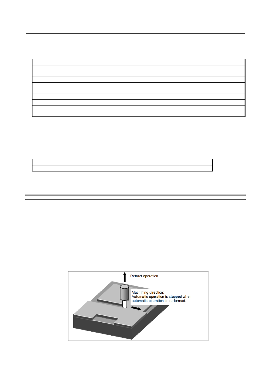
If the retract signal is set to 1 during automatic operation, a retract operation is performed and 
automatic operation is stopped. 

The retract completion signal becomes 0 when the tool has moved along one of the retract axes. 


Fig. 6.13 (a) 


B-64693EN-1/01


6. INTERPOLATION FUNCTION


- 1083 - 

Signal 

Retract signal RTRCT<Gn066.4> 

  [Classification]  Input signal 
 

[Function]  Causes the tool to retract along the axis for which a retract amount is set in the parameter. 


[Operation]  When this signal becomes 1, the CNC operates as described below. 

Captures the rise of the signal and causes the tool to retract along the axis for which 
a retract amount is set in parameter No. 7741. The retract amount and the retract 
speed assume the values previously set in parameters Nos. 7741 and 7740. 
After the end of retraction, the retract completion signal RTRCTF becomes 1. 
The retract signal is effective in either automatic operation mode (MEM, MDI) or 
manual mode (HNDL, JOG, etc.). 
If the retract signal is set to 1 during automatic operation, a retract operation is 
performed and automatic operation is stopped. 


Retract completion signal RTRCTF<Fn065.4> 

  [Classification]  Output signal 
 

[Function]  Notifies that retraction is completed. 


[Output cond.]  This signal becomes 1 when: 

A retract operation is completed. 
If a retract operation is performed on two or more axes, the operation is completed 
on all retract axes. 

It becomes 0 when: 

After the end of a retract operation, a move command is issued for one of the retract 
axes. 

Follow-up occurs due to a servo-off, emergency stop, or other conditions. 


NOTE 


While the retract completion signal is 1, the retract signal cannot be 
accepted. 


Signal address 


#7 

#6 

#5 

#4 

#3 

#2 

#1 

#0 

Gn066 


RTRCT 


#7 

#6 

#5 

#4 

#3 

#2 

#1 

#0 

Fn065 


RTRCTF 


Timing chart 

(1) RTRCT and RTRCTF on/off timing 


RTRCT 


RTRCTF 


Movement   Move           Retract operation                         Move  
             command                                              command 


Fig. 6.13 (b) 

6. INTERPOLATION FUNCTION


B-64693EN-1/01


- 1084 - 

(2) Interruption of retraction due to a reset 


RTRCT 


RTRCTF 


Movement 

      Interruption of 


      retract operation 

RST 


Turn the RTRCT signal off at the same time as turning the RST signal on. 


Fig. 6.13 (c) 

(3) Interruption of retraction due to an emergency stop 


RTRCT 


RTRCTF 


Movement 

      Interruption of 


      retract operation 

*ESP 


Turn RTRCT off at the same time as turning *ESP off.


Fig. 6.13 (d) 


Parameter 

7740 


Feedrate during retraction 


[Input type]  Parameter input 


[Data type]  Real axis 


[Unit of data]  mm/min, inch/min, deg/min (machine unit) 

[Min. unit of data]  Depend on the increment system of the applied axis 
[Valid data range]  Refer to the standard parameter setting table (C) 

(When the increment system is IS-B, 0.0 to +999000.0) 
This parameter sets the feedrate during retraction for each axis. 
 

7741 


Retract amount 


[Input type]  Parameter input 


[Data type]  Real axis 


[Unit of data]  mm, inch, deg (machine unit) 

[Min. unit of data]  Depend on the increment system of the applied axis 
[Valid data range]  9 digit of minimum unit of data (refer to standard parameter setting table (A)) 

(When the increment system is IS-B, -999999.999 to +999999.999) 
This parameter sets the retract amount for each axis. 

B-64693EN-1/01


6. INTERPOLATION FUNCTION


- 1085 - 


NOTE 


The tool moves (is retracted) by the specified amount regardless of 
whether diameter or radius programming is specified. 


#7 

#6 

#5 

#4 

#3 

#2 

#1 

#0 

7704 


ACR 


[Input type]  Parameter input 


[Data type]  Bit path 


#0  ACR

  In the AI contour control mode, general purpose retract operation is: 

0: 

Not Used. 

1: 

Used. 


7745 


Time constant for linear acceleration/deceleration in retract operation for each axis 


[Input type]  Parameter input 


[Data type]  word axis 


[Unit of data]  msec 

[Valid data range]  0 to 1000 

This parameter sets an acceleration rate for linear acceleration/deceleration in retract 
operation based on the general-purpose retract function. Set a time (Time constant) used 
to reach the federate set in parameter No.7740 for each axis. 
 

NOTE 


This parameter is valid when bit 0 (ACR) of parameter No. 7704 is 
set to 1 to perform a retract operation in the AI contour control 
mode. 


Caution 

  CAUTION 

1  A feedrate override is invalid to the retract speed. 
2  During a retract operation, an interlock to a retract axis is effective. 
3  During a retract operation, a machine lock to a retract axis is effective. The retract 

operation is completed in the machine lock state, and the retract completion 
signal is output. 

4  During retraction, a feed hold is invalid. 
5  The retract direction is the movement direction of the machine regardless of 

whether a mirrored image (signal and setting) is valid or not. (A mirror image is 
not applied to the updating of absolute coordinates.) 

6. INTERPOLATION FUNCTION


B-64693EN-1/01


- 1086 - 

  CAUTION 

6  When retraction is performed during automatic operation, the execution of a 

command is interrupted as soon as a retract operation starts. However, the 
operation state is switched to the automatic operation stopped state when the 
retract operation is completed. 


Automatic operation start 
signal (STL) 

Automatic operation 
suspend signal (SPL) 

Automatic operation 

in

-

progress signal (OP) 

Automatic operation 

Retract operation 

Start 

Start 

Command 
interruption 


7  Retract movement is effected with non-linear type positioning. 
8  During a retract operation, acceleration/deceleration assumes the 

acceleration/deceleration state at the start of retraction. In AI contour control 
mode, acceleration/deceleration before interpolation is not applied to a retract 
operation. By setting 1 in ACR, bit 0 of parameter No. 7704, and setting a retract 
time constant in parameter No. 7745, it is possible to apply linear 
acceleration/deceleration to a retract operation in AI contour control mode. 

9  During a retract operation, performing a reset or emergency stop causes the 

operation to be interrupted. In this case, the retract completion signal does not 
become 1. 

10 If, during following alarms are generated, the retract operation is interrupted. In 

this case, the retract completion signal does not become 1.   
With alarms other than following alarms, the retract operation is not interrupted 
-  Servo alarm 
-  Retract axis OT alarm 
-  PW alarm 
-  Alarm DS0001 or DS0002 

11 After the start of a retract operation, setting the retract signal RTRCT to 0 does 

not cause the retract operation to be interrupted. 

12 While the retract completion signal RTRCTF is 1, the retract signal RTRCT 

cannot be accepted. 

13 Even while a threading command is being executed, the retract function is 

effective. When the retract function is executed, the threading operation is 
stopped immediately, and a retract operation is started. 

14 Even in a canned cycle (during tapping), the retract function is effective. When 

the retract function is executed, the cycle operation is stopped immediately, and a 
retract operation is started. 

15 When retraction is performed on an axis on which movement is effected with 

PMC axis control, the move command for the PMC axis is not canceled. If, 
therefore, retraction is to be performed on a PMC axis on which movement is 
effected, set the retract signal RTRCT to 1 and use the PMC axis reset signal 
ECLRg to cancel PMC axis control. 

B-64693EN-1/01


6. INTERPOLATION FUNCTION


- 1087 - 

  CAUTION 

16 If an electronic gear box is attached, this function is invalid. 
17 If a group that has selected flexible synchronization control wishes to perform a 

retract operation when a sync mode is valid, the group must set the retract 
function for the master axis only. If the retract function is set for the slave axis, a 
retract operation is not performed normally. 

18 If general purpose retract is executed on an axis for which axis synchronous 

control is enabled, the parameters below causes a retract operation to be 
performed according to the settings of the master axis. 
-  Feedrate during retraction   

(parameter No. 7740) 

-  Retracted distance 

(parameter No. 7741) 

-  Time constant during retraction in AI contour control  (parameter No. 7745) 


Do not perform general purpose retract while the grid positioning automatic setup 
of axis synchronous control is being executed. 

19 This function cannot be used for axes related to 3-dimensional coordinate system 

conversion. 

20 When this function is used in the axis involved with Synchronous, Composite, or 

Superimposed control, alarm DS1934, “RETRACT CANNOT BE USED” is 
issued. Retract operation is not performed in the path including this axis. 


B-64693EN-1/01


- 1088 - 

7. FEEDRATE CONTROL/ACCELERATION AND 

DECELERATION CONTROL 

FEEDRATE CONTROL/ACCELERATION 
AND DECELERATION CONTROL 

7.1 

FEEDRATE CONTROL 

The feed functions control the feedrate of the tool. The following two feed functions are available: 
1. 

Rapid traverse   
When the positioning command (G00) is specified, the tool moves at a rapid traverse rate set in the 
CNC (parameter No. 1420). 

2. 

Cutting feed 
The tool moves at a programmed cutting feedrate. 

Override can be applied to a rapid traverse rate or cutting feedrate using the override signal. 
 

7.1.1 

Rapid Traverse Rate 

Overview 

The positioning command (G00) positions the tool by rapid traverse.   
 

G00 

IP

_ ; 

G00  :  G code (group 01) for positioning (rapid traverse) 

IP

_  :  Dimension word for the end point 

 
In rapid traverse, the next block is executed after each axis stops at the end point and the servo motor 
reaches a certain range set by the parameter No. 1826 (in-position check). 
A rapid traverse rate is set for each axis by parameter No. 1420 or No. 1428  (before reference position 
establishment), so no rapid traverse rate need be programmed. 
The following overrides can be applied to a rapid traverse rate with the rapid traverse override signals 
ROV1, ROV2<Gn014.0, 1>: F0, 25, 50, 100% 
F0:  Allows a fixed feedrate to be set for each axis by parameter No. 1421. 
The 1% step rapid traverse override selection signal HROV<Gn096.7> or 0.1% step rapid traverse 
override selection signal FHROV<Gn353.7> enables a rapid traverse override to be applied in steps of 
1% or 0.1% over a range of 0% to 100%. 
In case that bit 4 (RF0) of parameter No. 1401 is set to 1, the machine tool stops moving when cutting 
feedrate override is 0% during rapid traverse. 
Positioning  (G00)  is performed with either  non-linear  or  linear interpolation  can be specified by bit 1 
(LRP) of parameter No. 1401. 
Dry run for rapid traverse command is enabled by setting bit 6 (RDR) of parameter No. 1401 to 1. 
For details of override, refer to “Rapid traverse override”. 
For details of manual rapid traverse, refer to “JOG FEED/INCREMENTAL FEED”. 
 

Signal 

Rapid traversing signal RPDO<Fn002.1> 


  [Function]  This signal indicates that a move command is executed at rapid traverse. 

    [Output cond.]  1 indicates that an axis starts moving after rapid traverse has been selected in automatic 

operation mode or manual operation mode. 
0 indicates that an axis starts moving after a feedrate other than rapid traverse has been 
selected in automatic operation mode or manual operation mode. 
 

B-64693EN-1/01


- 1089 - 

7. FEEDRATE CONTROL/ACCELERATION 

AND DECELERATION CONTROL 

NOTE 

1  The rapid traverse in automatic operation includes all rapid 

traverses in canned cycle positioning, automatic reference point 
return, etc., as well as the move command G00. The manual rapid 
traverse also includes the rapid traverse in reference position 
return. 

2  This signal may be 1 when not only during axis movement but also 

when the axis is stopped.Once rapid traverse has been selected 
and movement is started, this signal remains 1, including during a 
stop, until another feedrate has been selected and movement is 
started. 


Signal address 


#7 

#6 

#5 

#4 

#3 

#2 

#1 

#0 

Fn002 


RPDO 


Parameter 


#7 

#6 

#5 

#4 

#3 

#2 

#1 

#0 

1401 


RDR 


RF0 


LRP 


[Input type]  Parameter input 


[Data type]  Bit path 


#1  LRP

  Positioning (G00) 

0: 

Positioning is performed with non-linear type positioning so that the tool moves 
along each axis independently at rapid traverse.   

1: 

Positioning is performed with linear interpolation so that the tool moves in a straight 
line. 

When using 3-dimensional coordinate system conversion, set this parameter to 1. 


#4  RF0

  When cutting feedrate override is 0% during rapid traverse, 

0: 

The machine tool does not stop moving. 

1: 

The machine tool stops moving. 


#6  RDR

  Dry run for rapid traverse command 

0: 

Disabled 

1: 

Enabled 


1420 


Rapid traverse rate for each axis 


[Input type]  Parameter input 


[Data type]  Real axis 


[Unit of data]  mm/min, inch/min, deg/min (machine unit) 

[Min. unit of data]  Depend on the increment system of the applied axis 
[Valid data range]  Refer to the standard parameter setting table (C) 

(When the increment system is IS-B, 0.0 to +999000.0) 
Set the rapid traverse rate when the rapid traverse override is 100% for each axis. 
 

1421 


F0 rate of rapid traverse override for each axis 


[Input type]  Parameter input 


[Data type]  Real axis 


[Unit of data]  mm/min, inch/min, deg/min (machine unit) 


Content      ..     139      140      141      142     ..