FANUC Series 0i-MODEL F Plus. CONNECTION MANUAL (FUNCTION) - page 131
 

  Index      Manuals     FANUC Series 0i-MODEL F Plus. CONNECTION MANUAL (FUNCTION) B-64693EN-1/01


Search            copyright infringement  


Content      ..     129      130      131      132     ..


FANUC Series 0i-MODEL F Plus. CONNECTION MANUAL (FUNCTION) - page 131


6. INTERPOLATION FUNCTION


B-64693EN-1/01


- 1002 - 

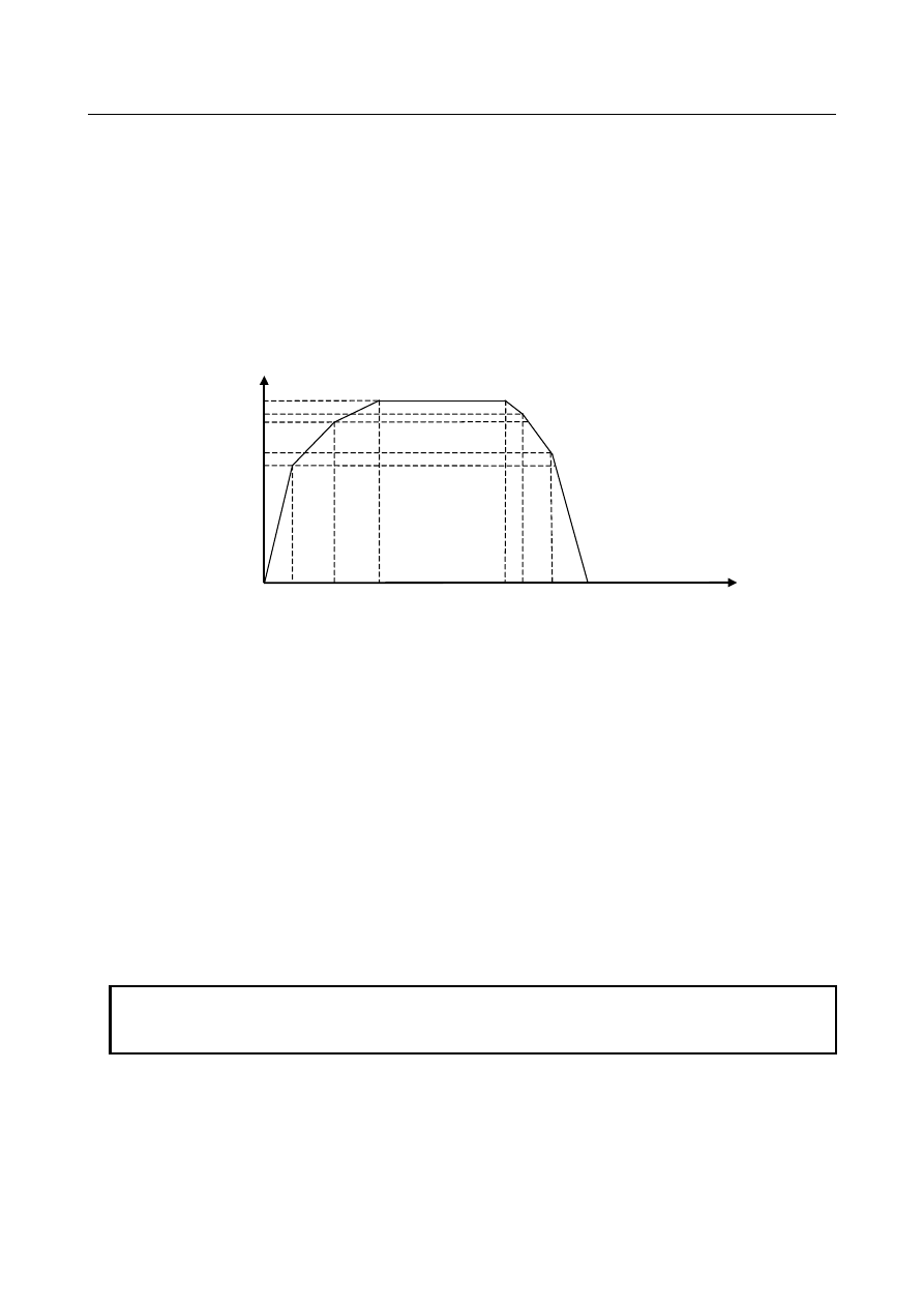
S

1

: value set in parameter No.11021 (Acceleration is switched at S

1

[min

-1

].) 

S : specified rotation speed[min

-1

A

a

  : value set in parameter No.11030 (Acceleration [min

-1

/s] applied from 0[min

-1

] to S

0

[min

-1

(section 1)) 

A

b

  : value set in parameter No.11031 (Acceleration [min

-1

/s]  applied  from S

0

[min

-1

] to S

1

[min

-1

(section 2)) 

A

c

  :  value set in parameter No.11032 (Acceleration [min

-1

/s] applied from S

1

[min

-1

] to maximum 

speed (section 3)) 


In addition, the deceleration can be set in other parameter by setting bit 6 (DCS) of parameter No.11001 
to 1. 


speed[min

-1

S

0


time[sec]


S

1


S


A

a


A

b


A

c


B

c


B

b


B

a


S

10


S

11


Fig.6.5.7.1 (f)  Acceleration/deceleration of spindle in arbitrary speed threading (exclusive parameter for 

deceleration) 

 
S

10

 : value set in parameter No.25700 (Deceleration is switched at S

10

[min

-1

].) 

S

11

 : value set in parameter No.25701 (Deceleration is switched at S

11

[min

-1

].) 

B

a

  : value set in parameter No.25710 (Deceleration [min

-1

/s] applied from 0[min

-1

] to S

10

  [min

-1

(section 1)) 

B

b

 : value set in parameter No.25711 (Deceleration [min

-1

/s] applied from S

10

 [min

-1

] to S

11

 [min

-1

(section 2)) 

B

c

 : value set in parameter No.25712 (Deceleration [min

-1

/s] applied from S

11

 [min

-1

] to maximum 

speed (section 3)) 

 
Determine the value of each parameter considering the torque characteristic of the motor and so on. 


- Spindle speed at the start of threading 

Spindle speed at the start of threading must be arrived at the specified speed in arbitrary speed threading. 
Therefore, threading can be started in the  mode if the difference between specified speed and feedback 
pulse from a position coder is smaller than the level set in parameter No.11490. 
 

NOTE 

  Speed arrival signals SARA to SARD <Fn045.3, Fn049.3, Fn168.3, Fn266.3> are 

always “1” while Cs contour control high speed switching completion signal is “1”. 


B-64693EN-1/01


6. INTERPOLATION FUNCTION


- 1003 - 

- Acceleration/Deceleration of feed axis and infeed axis in threading 

In threading, the axis whose travel distance is the longest is called a major axis. Thread is machined so 
that the specified lead would be applied in the direction of the major axis. In arbitrary speed threading, 
exclusive linear acceleration/deceleration is executed. Acceleration for the major axis is set in parameter 
No.11489. As for infeed axis (the second axis on the plane) performing taper threading and chamfering, 
acceleration is calculated from that of the major axis automatically. In continuous threading, acceleration 
of the major axis is applied from the first threading block to the last threading block. If the spindle speed 
override is changed, the spindle acceleration/deceleration is executed according to the switching point set 
in parameter No.11020, No.11021, and acceleration set in parameter No.11030 to No.11032, then, the 
major axis acceleration/deceleration is executed according to the spindle acceleration/deceleration. 
 
Example: continuous threading 
In block 1, acceleration for Z axis (major axis) is applied whose value is set in parameter No.11489, 
acceleration for X axis is calculated automatically. In block 2, the major axis is changed from Z axis to X 
axis because the chamfering angle is 60 degrees. But acceleration for Z axis is not changed (same as 
block 1), and acceleration for X axis is calculated automatically. 


Fig. 6.5.7.1 (g)  Acceleration/Deceleration of feed axis and infeed axis in threading 


NOTE 

1  Acceleration of a major axis must be higher than that of a spindle in order to 

machine without breaking the thread even if the spindle speed is changed. 
Acceleration of a major axis (parameter No.11489) must be set so that the 
acceleration would satisfy the following inequality. 

A

ax

>(A

sp

/60)*F 


Where, 

A

ax

 : acceleration of major axis set in parameter No.11489 

A

sp 

: maximum acceleration of spindle set in parameters No.11030 to 

No.11032, No.25710 to No.25712 

F : maximum lead specified in a machining program 


If the above condition is not satisfied, alarm PS0531 “THREADING PARAMETER 
ERROR” is issued. 

2  In continuous threading, if the feedrate of infeed axis (the second axis on the 

plane) cannot be decelerated to 0 with automatically calculated acceleration, 
alarm PS0529 is issued (For example when the major axis of block 1 and block 2 
is the second axis on the plane, and travel distance of block 2 is short.). 


Chamfering value and angle in thread cutting cycles 

In usual threading, parameter No.5130 for chamfering value in thread cutting cycles and parameter 
No.5131 for chamfering angle in thread cutting cycles are used. In arbitrary speed threading, the 
parameter is selected to use in chamfering by chamfering for arbitrary speed threading signal 
ASTC<Gn549.6>. 

-


Chamfering value and angle in usual thread cutting cycles (Parameters No.5130, No.5131) 

-


Chamfering value and angle in thread cutting cycles for arbitrary speed threading (Parameters 

No.11497, No.11498). 


  Z axis 
(feed axis) 

  X axis 
(infeed axis) 

G32 (block 1) 

G32 (block 2) 

60 degrees 

6. INTERPOLATION FUNCTION


B-64693EN-1/01


- 1004 - 

NOTE 


Use M code without buffering when ASTC <Gn549.6> is changed during arbitrary 
speed threading mode. 


- Retraction after chamfering for threading cycle and multiple threading cycle 

Feedrate, type of acceleration/deceleration, and time constant of retraction after chamfering (3. retraction 
of Fig. 6.5.7.1 (h) threading cycle) are as usual, as shown in Table 6.5.7.1 (c). 


Fig. 6.5.7.1 (h)  threading cycle 


Table 6.5.7.1 (c)    setting of acceleration/deceleration for retraction after chamfering 

Parameter CFR 

(No.1611#0) 

Parameter 

(No.1466) 

Description 

Other than 0 

Uses the type of acceleration/deceleration after interpolation for 
threading, time constant for threading (parameter No.1626), FL 
feedrate (parameter No.1627), and retraction feedrate specified in 
parameter No.1466. 

Uses the type of acceleration/deceleration after interpolation for 
threading, time constant for threading (parameter No.1626), FL 
feedrate (parameter No.1627), and rapid traverse rate specified in 
parameter No.1420. 


Before retraction, a check is made to see that the specified 
feedrate has become 0 (delay in acceleration/deceleration is 0), 
and the type of acceleration/deceleration after interpolation for 
rapid traverse is used together with the rapid traverse time constant 
and the rapid traverse rate (parameter No.1420). 

 
When the type of acceleration/deceleration after interpolation  for threading is used as the acceleration / 
deceleration for retraction after chamfering (bit 0 (CFRx) of parameter No.1611 is 1), acceleration / 
deceleration after interpolation for threading is acceleration/deceleration of exponential interpolation type. 
By setting bit 5 (THLx) of parameter No.1610, the same acceleration/deceleration for cutting feed can be 
selected (Followed by the setting of bits 1 (CTBx) and 0 (CTLx) of parameter No.1610). However, as a 
time constant and FL feedrate, the settings of parameter No.1626 and No.1627 for the threading cycle are 
used. 
 

NOTE 


Acceleration/deceleration after interpolation is invalid during arbitrary speed 
threading (2.threading in Fig. 6.5.7.1 (h) threading cycle), and 
acceleration/deceleration is controlled according to the exclusive acceleration. 
Retraction is started after finishing the deceleration of feed axis and infeed axis. 


- Maximum cutting feedrate 

If the cutting feedrate of feed axis or infeed axis exceeds the maximum cutting feedrate (parameter 
No.1430), cutting feedrate is clamped to the limit set in parameter No.1430, and the alarm PS0530 
“EXCESS VELOCITY IN THREADING” is issued. Threading is continued even if the alarm is issued. 

Start of cycle 

1. infeed 

3. retraction 

2. threading 

4. return 


B-64693EN-1/01


6. INTERPOLATION FUNCTION


- 1005 - 

Automatic operation is stopped after retracting in the case of threading cycle and multiple threading cycle. 
Automatic operation is stopped at the end of a block in the case of threading. 
 

- Acceleration/Deceleration after interpolation 

Acceleration/Deceleration after interpolation is ineffective in threading and chamfering. 
 

- Dry run 

Dry run is available according to the setting of bit 5 (TDR) of parameter No.1401. 
 

- Position gain 

Position gain of spindle (Cs contour control axis), position gain of feed axis, and position gain of infeed 
axis must be set the same value. 

-


feed axis, infeed axis 

parameter No.1825 

-


spindle (Cs contour control axis) 

parameter No.4069 (HIGH gear) 
parameter No.4070 (MEDIUM HIGH gear) 
parameter No.4071 (MEDIUM LOW gear) 
parameter No.4072 (LOW gear) 


- Gear change system 

T type gear selection method must be selected for the path which is applied arbitrary speed threading. 
 

- Path spindle control 

Start  and cancel command of arbitrary speed threading  must be specified in the same path.  The path 
specified M code of starting arbitrary speed threading and the path to which a spindle for arbitrary speed 
threading must be set bit 0 (AST) of parameter No.11485 to 1.  When the setting of bit 0 (AST) of 
parameter No.11485 is different because of the path specified M code of starting arbitrary speed threading 
and the path to which a spindle for arbitrary speed threading, it operates as follows. 

When the path specified M code is valid and the path to which a spindle is invalid: 
An alarm PS0531 “THREADING PARAMETER ERROR” occurs. M code is not output. 

When the path specified M code is invalid and the path to which a spindle is valid: 
It is not processed as M code for arbitrary speed threading. M code is output. 

It is not able to specify the same spindle as the axis performing arbitrary speed threading among multiple 
paths. When the spindle is already used in arbitrary speed threading mode at one path, if the command of 
starting arbitrary speed threading is specified to the same  spindle at other path, the alarm PS0529 
“THREADING COMMAND IMPOSSIBLE” is issued. 
 
Set parameters for arbitrary speed threading as follows. 
Path A: The path specified M code of starting arbitrary speed threading 
Path B: The path to which a spindle for arbitrary speed threading 
 

Necessary parameters both path A and path B to set 

Parameter No. 

Explanation 

No.11485#0 

Arbitrary speed threading is valid 


Necessary parameter for path A to set 

Parameter No. 

Explanation 

No.11486#0 

Command for shifting the threading start angle by address Q in re-machining thread is invalid 
(0) / valid (1) 

No.11486#1 

Arbitrary speed threading mode is canceled (0) / not canceled (1) by reset 

No.11486#2 

In arbitrary speed threading mode, M code to start arbitrary speed threading mode is invalid 
(0) / valid (1) to command 

No.11489 

Acceleration of major axis in arbitrary speed threading (set to major axis) 

6. INTERPOLATION FUNCTION


B-64693EN-1/01


- 1006 - 

Necessary parameter for path A to set 

Parameter No. 

Explanation 

No.11490 

Spindle speed arrival level in arbitrary speed threading 

No.11492 

Adjusting parameter 1 for arbitrary speed threading (position error of servo) 

No.11493 

Adjusting parameter 2 for arbitrary speed threading (position error of spindle) 


Necessary parameter for path B to set 

Parameter No. 

Explanation 

No.11487 

M code to start arbitrary speed threading mode 

No.11488 

M code to cancel arbitrary speed threading mode 

No.11030 

Individual acceleration/deceleration 

No.11031 

Individual acceleration/deceleration 

No.11032 

Individual acceleration/deceleration 

No.4002#4 

In Cs contour control, the rotation direction signal (SFR/SRV) function is used / not used. 
(Please set to 1) 

No.4069 

Position gain in Cs contour control (HIGH gear) 

No.4070 

Position gain in Cs contour control (MEDIUM HIGH gear) 

No.4071 

Position gain in Cs contour control (MEDIUM LOW gear) 

No.4072 

Position gain in Cs contour control (LOW gear) 

No.4504 

Cs contour control high speed switching: Reference position establishment speed 

No.4505 

Cs contour control high speed switching: Reference position establishment acceleration 

No.4506 

Cs contour control high speed switching: Bell-shaped acceleration/deceleration time constant 
for the reference position establishment 

No.4507 

Cs contour control high speed switching: Reference position establishment completion level 


Note 

- Emergency stop   

A spindle (Cs contour control axis) is stopped by emergency stop *ESP <X008.4> (for the first machine 
group), <X008.0> (for the second machine group), <X008.1> (for the third machine group), and 
<Gn008.4> during arbitrary speed threading. 
 

- Spindle stop 

A spindle can be stopped by the following operations during arbitrary speed threading. 

Spindle stop signal *SSTP<Gn029.6>, individual spindle stop signal *SSTP1 to *SSTP4<Gn027.3 
to Gn027.5, Gn026.6> (using multi-spindle control) 

Spindle speed override signal, individual spindle speed signal 

S0 command 

Arbitrary speed threading must be canceled when a spindle is stopped by an operation except above 
during arbitrary speed threading. Besides, a spindle is stopped by servo alarm or servo-off differently 
from usual spindle control. 
 

- Machine lock 

All-axis machine lock signal MLK<Gn044.1> and each-axis machine lock signals MLK1 to 
MLK8<Gn0108> are ineffective for a spindle during arbitrary speed threading. These signals are 
effective before threading. But these signals are ineffective during threading including chamfering. 
 

- Interlock 

All axes interlock signal *IT<Gn008.0> and interlock signals for each axis *IT1 to *IT8<Gn130> are 
ineffective for a spindle during arbitrary speed threading. 
 

- Stored stroke check 

Stored stroke check is ineffective for a spindle during arbitrary speed threading.   
 

B-64693EN-1/01


6. INTERPOLATION FUNCTION


- 1007 - 

- Arbitrary speed threading in Cs contour control 

If the M code for start of arbitrary speed threading is specified in Cs contour control mode, the alarm 
(PS0529) ” THREADING COMMAND IMPOSSIBLE” is issued. Changing to arbitrary speed threading 
mode is permitted in only spindle rotation control mode. 
 

- Simple spindle electronic gear box 

The slave axis synchronizes by following to the master axis, therefore, the slave axis is required a higher 
acceleration ability than that of the master axis. If the acceleration ability of the master axis is higher than 
that of the slave axis, the acceleration/deceleration of the master axis should be set in consideration of the 
acceleration ability of the slave axis.  Moreover, the spindle which is commanded in  arbitrary speed 
threading mode should be a master axis.   


- Spindle speed 

When bit 3 (IRC) of parameter No.1408 is set to 0,  the malfunction prevent function may work at a 
rotation speed of about 2778 min

-1

. When the motor rotates at a rotation speed of 2778 min

-1

 or more, set 

bit 3 (IRC) of parameter No.1408 to 1. If bit 3 (IRC) of parameter No.1408 is set to 1, a rotation speed 
can be specified up to about 27778 min

-1


Limitation 

Reference position return 

As a rule, in order to use this function, reference position return must be performed in Cs contour control 
once after power-on to detect the one-rotation signal of the spindle. If arbitrary speed threading mode 
change is executed without performing reference position return, the spindle decelerates to the reference 
position return speed (parameter No.4074) in order to detect the one-rotation signal. After detecting the 
one-rotation signal, one-rotation signal detection status signal for Cs contour control CS1DTx 
(<Fn047.6> (1st spindle), <Fn051.6> (2nd spindle), <Fn170.6> (3rd spindle), <Fn268.6> (4th spindle)) 
become “1”. 
 

Unavailable functions for arbitrary speed threading 

-


Pitch error compensation 
Pitch error compensation is not available for spindle in arbitrary speed threading. 

-


Synchronous control and composite control 

Synchronous control and composite control are not available for the first axis on the plane, the 
second axis on the plane, and the spindle during arbitrary speed threading. Alarm PS0529 
“THREADING COMMAND IMPOSSIBLE” is issued. 

-


Superimposed control 

Superimposed control is not available for the first axis on the plane, the second axis on the plane, 
and the spindle during arbitrary speed threading. Alarm PS0529 “THREADING  COMMAND 
IMPOSSIBLE” is issued. 

-


Spindle synchronous control 

-


Spindle command synchronous control   

Both spindle synchronous control and spindle command synchronous control are not available for 
the spindle during arbitrary speed threading. Alarm PS0529 “THREADING  COMMAND 
IMPOSSIBLE” is issued. 

-


Manual reference position return 

If manual reference position return for spindle is performed in arbitrary speed threading mode, 
alarm PS0529 “THREADING COMMAND IMPOSSIBLE” is issued. 

-


Arbitrary reference position setting function 

-


Cs contour control axis coordinate establishment 

Both arbitrary reference position setting function and Cs contour control axis coordinate 
establishment are not available for a spindle during arbitrary speed threading. 

-


Spindle control with a servo motor 

Arbitrary speed threading is not available for a spindle which is controlled with a servo motor. 

-


Spindle analog output 

6. INTERPOLATION FUNCTION


B-64693EN-1/01


- 1008 - 

Arbitrary speed threading is not available for analog spindle. 

-


Usual threading 
Usual threading is not available during arbitrary speed threading mode. Arbitrary speed threading 

must be canceled to enable usual threading. 

-


Manual handle retrace 

-


Spindle output control by the PMC 

-


Balance cutting 

-


Mirror image for double turret 

Arbitrary speed threading is not available during double turret mirror image mode. 

-


Flexible path axis assignment 
Arbitrary speed threading is not available for a spindle which is assigned/exchanged by flexible 
path axis assignment. 

-


Constant surface speed control 
Arbitrary speed threading is not available in constant surface speed control. 
 

Spindle software functions 

The following functions cannot be used with arbitrary speed threading. 

-


  Spindle electronic gear box (spindle EGB) 

-


  Dual position feedback function 


6.5.7.2 

Re-machining thread 

Overview 

This function makes it possible to re-machine the same thread even if the workpiece which is not finished 
threading is removed from a chuck once. In order to re-machine the thread, groove of thread is measured 
after mounting the workpiece on a chuck. Then,  the thread is re-machined by the same machining 
program. This function is included in “Arbitrary speed threading”. 
 

Explanation


In order to re-machine the thread, the groove of thread is measured. Then, re-machining thread signal 
RMTC<Gn549.5> is set to “1”, and re-machining thread is executed in arbitrary speed threading mode. 
This function is enabled by setting bit 1 (RMT) of parameter No.11485 to 1. 
 

Measurement of thread groove 


- Measurement of thread groove in arbitrary speed threading mode 

1.)


Change to  arbitrary speed threading mode by specifying M code on condition that the spindle is 
stopped (S0). 

2.)


In manual operation, touch the tool to a groove of thread. 

3.)


In order to measure the groove of thread, groove of thread measurement signal GTMSR <Gn549.4> 
is set to “1”. Groove of thread measurement signal GTMSR <Gn549.4> is set to “0” after groove of 
thread measurement completion signal GTMC <Fn546.4> becomes “1”. Machine coordinates of each 
axis are stored in parameter No.11496 by measuring the groove of thread. 

4.)


Retract the tool. 

5.)


Cancel arbitrary speed threading by specifying M code. 


  CAUTION 

1  In changing to arbitrary speed threading mode, the spindle rotates at a speed of 

parameter No.4504 to No.4506, and reference position establishment is 
performed. 

2  Spindle should not be rotated from the end of reference position establishment to 

the end of measurement of thread groove. 


B-64693EN-1/01


6. INTERPOLATION FUNCTION


- 1009 - 

- Measurement of thread groove with reference position return in Cs contour 

control mode 

In case that a spindle used in re-machining thread is in Cs contour control mode (Cs contour control 
change completion signal FSCSL <Fn044.1> or Cs contour control change completion signals in each 
axis FCSSx <Fn274.0 to 3 = “1”) and reference position return is completed (reference position return 
end signals ZPx<Fn094.0 to 8>=”1”), measuring thread groove is possible. By this way, measuring thread 
groove can be performed only by operating signals without executing automatic operation. 
1) 

Change to Cs contour control mode on condition that the spindle used in re-machining thread is 
stopped (S0), and reference position return must be performed. At this time, feedback pulse from 
this spindle position coder must be selected during measurement of thread groove. 

2) 

In manual operation, touch the tool to a groove of thread. 

3) 

In order to measure the groove of thread, groove of thread measurement signal GTMSR <Gn549.4> 
is set to “1”. Groove of thread measurement signal GTMSR <Gn549.4> is set to “0” after groove of 
thread measurement completion signal GTMC <Fn546.4> becomes “1”. Machine coordinates of 
each axis are stored in parameter No.11496 by measuring the groove of thread. 

4) 

Retract the tool. 

5) 

Cancel Cs contour control mode 


  CAUTION 

1  The spindle whose feedback pulse from position coder is effective is recognized 

as a spindle used in re-machining thread. So if another spindle is selected by 
mistake, groove of thread measurement error (groove of thread measurement 
error signal GTME<Fn546.5>=”1”) occurs or thread cutting is not performed 
correctly, so be careful to select the proper spindle. 

2  If the spindle whose feedback pulse from position coder is effective is not in the 

state of reference position return end, groove of thread measurement error 
(groove of thread measurement error signal GTME<Fn546.5>=”1”) occurs. 


Fig. 6.5.7.2 (a)    measurement of thread groove 


Content      ..     129      130      131      132     ..