FANUC Series 0i-MODEL F Plus. CONNECTION MANUAL (FUNCTION) - page 132
 

  Index      Manuals     FANUC Series 0i-MODEL F Plus. CONNECTION MANUAL (FUNCTION) B-64693EN-1/01


Search            copyright infringement  


Content      ..     130      131      132      133     ..


FANUC Series 0i-MODEL F Plus. CONNECTION MANUAL (FUNCTION) - page 132


6. INTERPOLATION FUNCTION


B-64693EN-1/01


- 1010 - 

  CAUTION 

1  The groove of thread must be measured when axes except for PMC axis, and 

spindle for arbitrary speed threading are stopped. 

2  The groove of thread must be measured with the same tool which is used for 

re-machining thread. Besides, tool offset should not be changed from 
measurement of thread groove to re-machining. 


NOTE 


The groove of thread cannot be measured in servo-off state. 


Re-machining thread 

Re-machining thread signal GTMC<Gn549.5> is set to “1”, then arbitrary speed threading is specified. If 
the re-machining is finished, re-machining thread signal GTMC<Gn549.5> is set to “0”. 
 
<Re-machining thread signal GTMC<Gn549.5> is set to “1”> 
 
S_;                       : specifying the spindle speed 
Mxx;                     : start of arbitrary speed threading 
N1G92 X151.0Z-200.F10.; 
N2X150.0;   
N3X149.0;   
N4X148.0;   
G00; 
Myy;                     : cancel of arbitrary speed threading 
 
<Re-machining thread signal GTMC<Gn549.5> is set to “0”> 
 

NOTE 

1  If arbitrary speed threading is executed with re-machining thread signal 

GTMC<Gn549.5> setting to “1”, the timing of threading start is changed 
according to the measured data of thread groove. Therefore, re-machining thread 
signal GTMC<Gn549.5> should be set to “0” while re-machining thread is not 
executed. 

2  If re-machining thread is executed without measuring the groove of thread after 

power-on, the alarm PS0532 ”RE-MACHINING OF THREAD CUTTING 
IMPOSSIBLE” is issued. 


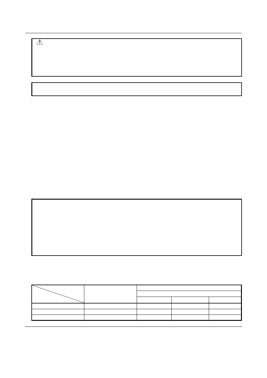
- Available threading commands for re-machining thread 

Threading commands which are available for re-machining are as follows. 
 

Table 6.5.7.2 (a)  Available threading commands for re-machining thread 


Machining center system 

Lathe system 

G code system 

Threading 

G33 

G32 

G33 

G33 

Threading cycle 


G92 

G78 

G21 

Multiple threading cycle 


G76 

G76 

G78 


Note 

- Measurement of thread groove 

Measurement position must be the groove except for chamfering part in the case of threading cycle, or the 
first block groove in the case of continuous threading. 

B-64693EN-1/01


6. INTERPOLATION FUNCTION


- 1011 - 


- Re-machining thread 

The workpiece which is machined by usual threading can be re-machined. Since re-machining is 
controlled in arbitrary speed threading mode, re-machined thread may not have the same thread shape 
completely due to the difference of acceleration/deceleration method. The difference of thread shape may 
occur at chamfering part of threading cycle or taper part for chamfering of continuous threading. 
 

- Re-machining thread signal 

If arbitrary speed threading is executed with re-machining thread signal GTMC<Gn549.5> setting to “1”, 
the timing of threading start is changed according to the measured data of thread groove. Therefore, 
re-machining thread signal GTMC<Gn549.5> should be set to “0”  while re-machining thread is not 
executed. 
 

- Command for shifting the threading start angle by address Q 

Whether the command for shifting the threading start angle by address Q is enabled  or not is selected 
according to bit 0 (ADQ) of parameter No.11486. 
 

Bit 0 (ADQ) of parameter No.11486 is set to 0 


The command for shifting the threading start angle by address Q is disabled for re-machining thread. 
The tool passes the measured groove of thread regardless of Q command. 


Bit 0 (ADQ) of parameter No.11486 is set to 1 


The command for shifting the threading start angle by address Q is enabled for re-machining thread. 
The measured position of thread groove is assumed to be standard angle (Q=0), and the shift of the 
threading start angle commanded by address Q is added. 


6. INTERPOLATION FUNCTION


B-64693EN-1/01


- 1012 - 

  CAUTION 

  -  When bit 0 (ADQ) of parameter No.11486 is set to 1: 
 
   In re-machining the thread which is machined the following program, the groove 

of thread which is machined by address Q=0 must be measured. 

 
    Example) 
 
         G32 Z-200.0 F10.0 Q0 ; 
             : 
         G32 Z-200.0 F10.0 Q90000 ; 
             : 
 
   If the groove of thread which is machined by address Q=90000 is measured, and 

re-machining is executed by above program, thread is re-machined as shown in 
Fig. 6.5.7.2 (b). 


Fig. 6.5.7.2 (b)  Example of re-machining thread in bit 0 (ADQ) of parameter No.11486 is set to 1. 


Measurement 

Q = 0 

Q = 90000 

Q = 0 

Q = 90000 

Q = 0 

Q = 90000 

Q = 0 

Q = 90000 

Re-machining thread 

Measurement of thread groove 

B-64693EN-1/01


6. INTERPOLATION FUNCTION


- 1013 - 

Limitation 

- Multiple threading cycle 

Cutting method of multiple threading cycle is usually one-edge threading with constant cutting amount as 
shown in Fig. 6.5.7.2 (c) (1). Re-machining of multiple threading cycle is executed so that the groove of 
thread would be machined at the stored position by measurement as shown in Fig. 6.5.7.2 (c) (2). 


(1) Usual multiple 

threading cycle 

a : angle of tool nose 

k : height of thread 

Δ

d : depth of cut in 1

st

 cut 

d : finishing allowance 

1st 

2nd 

3rd 

nth 

Δ

Δ

d

Δ

d

Δ

d

Measurement of the 
thread groove 

(2) Re-machining of multiple 

threading cycle 


Fig. 6.5.7.2 (c)    cutting method of multiple threading cycle re-machining 

 
In the case of memory operation using Series 15 format, even if the following cutting method is selected, 
re-machining of multiple threading cycle is executed as shown in Fig. 6.5.7.2 (c) (2), too. 
 
    P1 : one-edge threading with constant cutting amount 
    P2 : both-edge zigzag threading with constant cutting amount 
    P3 : one-edge threading with constant depth of cut 
    P4 : both-edge zigzag threading with constant depth of cut 
 

- Mirror image 

Thread cannot be re-machined with mirror image applied. 
 

Signal 

1st spindle speed override signal SOV0 to SOV7<Gn030> 
2nd spindle speed override signal SOV20 to SOV27<Gn376> 
3rd spindle speed override signal SOV30 to SOV37<Gn377> 
4th spindle speed override signal SOV40 to SOV47<Gn378> 

  [Classification]  Input signal 
 

[Function]  If bit 3 (MSC) of parameter No.3713 = 1, and bit 4 (EOV) of parameter No.3713 = 1, an 

override of 0% to 254% of the rotation speed specified by the CNC can be applied to 
individual spindles separately. 


[Operation]  Specify an override value, using an 8-bit binary number. 

If all bits are “1”, however, an override of 0% is assumed.   
 

NOTE 

If both bit 3 (MSC) and bit 4 (EOV) of parameter No.3713 are not 1, 
the override signals SOV0 to SOV7 are applied to all spindles that 
receive speed commands. 
The signals SOV20 to SOV27, SOV30 to SOV37, and SOV40 to 
SOV47 are invalid. 


6. INTERPOLATION FUNCTION


B-64693EN-1/01


- 1014 - 

Cs contour control high speed switching signals   
 

CONH1 to CONH4<Gn549.0 to Gn549.3> 

  [Classification]  Input signal 
 

[Function]  These signals specify high speed switching from spindle rotation control to Cs contour 

control. 
When these signals are set to “1”, setting the Cs contour control change signal CON 
<Gn027.7> (or the Cs contour control change signal in each axis CONSx <Gn274.0 to 
Gn274.3>) from “0” to “1” starts Cs contour control high speed switching. 
When these signals are set to “0”, setting CON (or CONS) from “0” to “1” starts ordinary 
switching to Cs contour control. 
Setting CON (or CONS) from “1” to “0” switches to spindle rotation control. The type of 
switching is the same as of switching to Cs contour control. 
These signals are valid when bit 0 (AST) of parameter No.11485 is set to 1. 
 

Cs contour control high speed switching completion signals   
 

CSMC1 to CSMC4<Fn546.0 to Fn546.3> 

  [Classification]  Output signal 
 

[Function]  These signals notify the PMC that the system is put in the Cs contour control mode by Cs 

contour control high speed switching. 


[Output cond.]  These signals become “1” under the following condition: 

  - 

The system is put in the Cs contour control mode by Cs contour control high speed 
switching. 

These signals become “0” under the following condition: 
  - 

The system is put in the Cs contour control mode by ordinary switching to Cs 
contour control. 

  - 

The system is not in the Cs contour control mode. 


Forward rotation / Reverse rotation command signal (serial spindle) 
 

SFRA/SRVA<Gn070.5/Gn070.4> : First spindle 


SFRB/SRVB<Gn074.5/Gn074.4> : Second spindle 


SFRC/SRVC<Gn204.5/Gn204.4> : Third spindle 


SFRD/SRVD<Gn266.5/Gn266.4> : Fourth spindle 

  [Classification]  Input signal 
 

[Function]  These signals switch between on and off of motor excitation in Cs contour control. 


[Operation]  When this function is used, in Cs contour control, keep SFRx or SRVx to “1” during: 

Mode switching from spindle rotation control to Cs contour control 
Mode switching from Cs contour control to spindle rotation control 
 

NOTE 

When SFRx (or SRVx) is set to “0” during mode switching from 
spindle rotation control to Cs contour control, the spindle 
decelerates, then reference position establishment is performed. 


Reference position establishment starting signal (serial spindle) 
 

CSYCA<Gn304.3> : First spindle 


CSYCB<Gn308.3> : Second spindle 


CSYCC<Gn312.3> : Third spindle 


CSYCD<Gn316.3> : Fourth spindle 

  [Classification]  Input signal 
 

[Function]  These signals establish the reference position while the spindle is rotating. 


[Operation]  Setting these signals to “0”  after the reference position establishment starting signal 

CSYCx is set to “1” starts to establish the reference position while the spindle is rotating. 
 

B-64693EN-1/01


6. INTERPOLATION FUNCTION


- 1015 - 

Reference position establishment completion signal (serial spindle) 
 

CSYFNA<Fn047.7> : First spindle 


CSYFNB<Fn051.7> : Second spindle 


CSYFNC<Fn170.7> : Third spindle 


CSYFND<Fn268.7> : Fourth spindle 

  [Classification]  Output signal 
 

[Function]  These signals indicate that reference position establishment while the spindle is rotating is 

completed. 


[Output cond.]  These signals become “1” under the following condition: 

  - 

Reference position establishment while the spindle is rotating is completed. 

These signals become “0” under the following condition: 
  - 

Reference position establishment while the spindle is rotating is not completed. 

  - 

The system is in the spindle rotation control mode. 


One-rotation signal detection status signal for Cs contour control (serial spindle) 
 

CS1DTA<Fn047.6> : First spindle 


CS1DTB<Fn051.6> : Second spindle 


CS1DTC<Fn170.6> : Third spindle 


CS1DTD<Fn268.6> : Fourth spindle 

  [Classification]  Output signal 
 

[Function]  These signals indicate that the one-rotation signal has been detected in Cs contour 

control. 


[Output cond.]  These signals become “1” under the following condition: 

  - 

The one-rotation signal has been detected in Cs contour control. 

These signals become “0” under the following condition: 
  - 

The one-rotation signal has not been detected in Cs contour control. 


SV reverse signals SVRVS1 to SVRVS8<Gn523> 

  [Classification]  Input signal 
 

[Function]  These signals cause the respective axes to reverse their rotation direction in the arbitrary 

speed threading mode. 


[Operation]  Setting these signals to “1” cause the respective axes to reverse their rotation direction. 

Resetting these signals to “0”  cause the respective axes to resume their normal rotation 
direction. 
 

NOTE 

  In this function, because spindle rotation control mode is switched to 

arbitrary speed threading mode (position control) immediately while 
the spindle is rotating, rotation direction in arbitrary speed threading 
might be switched from that in spindle rotation control due to 
machine configuration or parameter setting. For this case, SV 
reverse signal SVRVS1 to SVRVS8 <Gn523> is set to “1” before 
changing to arbitrary speed threading mode so that the rotation 
direction in arbitrary speed threading would be the same as that in 
spindle rotation control. Besides, SV reverse signal SVRVS1 to 
SVRVS8 <Gn523> is set to “0” after canceling the arbitrary speed 
threading mode. 


Groove of thread measurement signal GTMSR<Gn549.4> 

  [Classification]  Input signal 
 

[Function]  The groove of thread is measured.   

6. INTERPOLATION FUNCTION


B-64693EN-1/01


- 1016 - 


[Operation]  When groove of thread measurement signal is set to “1”, the groove of thread is 

measured.   
 

Groove of thread measurement completion signal GTMC<Fn546.4> 

  [Classification]  Output signal 
 

[Function]  Completion of thread groove measurement is indicated. 


[Output cond.]  This signal becomes “1” when: 

  - 

Groove of thread measurement signal is set to “1”, then the measurement of thread 
groove is completed. 

This signal becomes “0” when: 
  - 

Groove of thread measurement signal is set from “1” to “0”. 


Groove of thread measurement error signal GTME<Fn546.5> 

  [Classification]  Output signal 
 

[Function]  It indicates that error is detected while measurement of thread groove. 


[Output cond.]  This signal becomes “1” when: 

  - 

The groove of thread is measured when axes except for PMC axis, and spindle (for 
arbitrary speed threading) are not stopped. This signal becomes “1” when the groove 
of thread measurement completion signal becomes “1” at the same time. This signal 
becomes “0” when: 

  - 

Groove of thread measurement signal is set from “1” to “0”. 


Sequence of thread groove measurement 


Fig. 6.5.7.2 (d)    completion of thread groove measurement 


Fig. 6.5.7.2 (e)    error of thread groove measurement 


Re-machining thread signal RMTC<Gn549.5> 

  [Classification]  Input signal 
 

[Function]  Re-machining thread is executed. 


[Operation]  In order to re-machine the thread, arbitrary speed threading is executed with setting this 

signal to “1”. 

Groove of thread measurement signal 
GTMSR 

Groove of thread measurement completion signal 
GTMC


Groove of thread measurement error signal


GTME


Groove of thread measurement signal 
GTMSR 

Groove of thread measurement completion signal 
GTMC


Groove of thread measurement error signal


GTME


B-64693EN-1/01


6. INTERPOLATION FUNCTION


- 1017 - 

If re-machining thread is executed without measuring the groove of thread after power-on, 
the alarm PS0532 “RE-MACHINING OF THREAD CUTTING IMPOSSIBLE” is issued. 
This signal may be set to “1”  in arbitrary speed threading. However, in this case, this 
signal must be set to “1”  while the buffering is prevented by specifying M code of 
preventing buffering. 


Chamfering for arbitrary speed threading signal ASTC<Gn549.6> 

  [Classification]  Input signal 
 

[Function]  In arbitrary speed threading, the parameter is selected to use with chamfering value and 

angle in thread cutting cycles. 


[Operation]  When ASTC is “0”, chamfering value and angle in usual thread cutting cycles 

(Parameters No.5130, No.5131) are used. 
When ASTC is “1“, chamfering value and angle in thread cutting cycles for arbitrary 
speed threading (Parameters No.11497, No.11498) are used. 
 

Signal address 


#7 

#6 

#5 

#4 

#3 

#2 

#1 

#0 

Gn030 


SOV7 

SOV6 

SOV5 

SOV4 

SOV3 

SOV2 

SOV1 

SOV0 


#7 

#6 

#5 

#4 

#3 

#2 

#1 

#0 

Gn376 


SOV27 

SOV26 

SOV25 

SOV24 

SOV23 

SOV22 

SOV21 

SOV20 


#7 

#6 

#5 

#4 

#3 

#2 

#1 

#0 

Gn377 


SOV37 

SOV36 

SOV35 

SOV34 

SOV33 

SOV32 

SOV31 

SOV30 


#7 

#6 

#5 

#4 

#3 

#2 

#1 

#0 

Gn378 


SOV47 

SOV46 

SOV45 

SOV44 

SOV43 

SOV42 

SOV41 

SOV40 


#7 

#6 

#5 

#4 

#3 

#2 

#1 

#0 

Gn523 


SVRVS8


SVRVS7 

SVRVS6 

SVRVS5 

SVRVS4 

SVRVS3 

SVRVS2 

SVRVS1 


#7 

#6 

#5 

#4 

#3 

#2 

#1 

#0 

Gn549 


ASTC 

RMTC 

GTMSR 

CONH4 

CONH3 

CONH2 

CONH1 


#7 

#6 

#5 

#4 

#3 

#2 

#1 

#0 

Fn546 


GTME 

GTMC 

CSMC4 

CSMC3 

CSMC2 

CSMC1 


- For first serial spindle 


#7 

#6 

#5 

#4 

#3 

#2 

#1 

#0 

Gn070 


SFRA 

SRVA 


#7 

#6 

#5 

#4 

#3 

#2 

#1 

#0 

Gn304 


CSYCA 


#7 

#6 

#5 

#4 

#3 

#2 

#1 

#0 

Fn047 


CSYFNA 

CS1DTA 


- For second serial spindle 


#7 

#6 

#5 

#4 

#3 

#2 

#1 

#0 

Gn074 


SFRB 

SRVB 


#7 

#6 

#5 

#4 

#3 

#2 

#1 

#0 

Gn308 


CSYCB 


Content      ..     130      131      132      133     ..