FANUC Series 0i-MODEL F Plus. CONNECTION MANUAL (FUNCTION) - page 124
 

  Index      Manuals     FANUC Series 0i-MODEL F Plus. CONNECTION MANUAL (FUNCTION) B-64693EN-1/01


Search            copyright infringement  


Content      ..     122      123      124      125     ..


FANUC Series 0i-MODEL F Plus. CONNECTION MANUAL (FUNCTION) - page 124


5. AUTOMATIC OPERATION


B-64693EN-1/01


- 946 - 

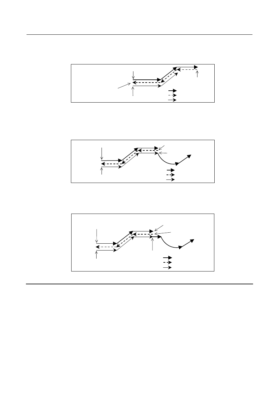
Even when a cycle start operation is performed while the reverse execution signal RVS is held 1, 
operation is not performed, and the reverse execution end state is maintained. Forward reexecution (or 
forward execution) is started by setting the reverse execution signal RVS to 0 then performing a cycle 
start operation. 


End of reverse execution 
Reverse execution signal RVS = 0 
Cycle start 
 

Cycle start (start of forward execution) 
 

Start of forward reexecution 

Forward 
Reverse 
Forward reexecution 
 

Start of reverse execution 


Fig. 5.10 (g) 


  - 

Forward reexecution 

 forward execution 

After forward reexecution is performed up to the block at which reverse execution started, forward 
execution starts automatically, and commands are read from the program again and executed. No 
particular operation is required. 


Cycle start (start of forward execution) 


Start of forward reexecution 
 

Forward 
Reverse 
Forward reexecution 
 

Start of reverse execution 

Restart of forward execution 


Fig. 5.10 (h) 

 
If reverse execution was performed after feed hold stop, forward reexecution ends when the feed hold 
stop position is reached, then forward execution is performed. Also if single block operation was 
performed, forward reexecution ends at the single block stop position. 


Cycle start (start of forward execution) 

Start of forward reexecution 

Forward 
Reverse 
Forward reexecution 

Feed hold stop 
Reverse execution signal RVS = 1, cycle start 

Start of reverse execution 

Restart of forward execution 


Fig. 5.10 (i) 


Description 

  - 

Reverse execution and forward execution 

Usually in automatic operation, a program is executed in the programmed order. This is called forward 
execution. This function allows a program executed by forward execution to be executed in the reverse 
direction. This is called reverse execution. Reverse execution allows the tool to retrace the path along 
which the tool has moved during forward execution. 
Reverse execution of a program can be performed only for blocks that have been executed by forward 
execution. 
Furthermore, in single block operation, reverse execution can also be performed on a block-by-block 
basis. 
 

B-64693EN-1/01


5. AUTOMATIC OPERATION


- 947 - 

  - 

Forward reexecution 

Blocks that have been executed by reverse execution can be reexecuted in the forward direction up to the 
block from which reverse execution started. This is called forward reexecution. Forward reexecution 
allows the tool to retrace the same tool path as in forward execution until the position at which reverse 
execution started is reached. 
After the block from which reverse execution started is reached, the program is executed again in the 
programmed order (forward execution). 
Furthermore, in single block operation, forward reexecution can also be performed on a block-by-block 
basis. 
 

  - 

End of reverse execution 

When a block to be executed is no longer present during reverse execution (when stored blocks have all 
been executed during reverse execution, or when forward execution has not yet been performed), 
operation stops. This is called the end of reverse execution. 
 

  - 

Status indication 

During reverse execution, characters "RVRS" blink on the screen. During forward reexecution, characters 
"RTRY" blink to indicate that forward reexecution is in progress. The "RTRY" indication is kept blinking 
until the block at which reverse execution started is reached and normal operation starts (until forward 
execution is restarted). 
When a block to be executed is no longer present during reverse execution, or if an attempt is made to 
perform reverse execution for a block that cannot be executed by reverse execution, characters "RVED" 
blink, notifying the user that reverse execution can no longer be performed. 
 

  - 

Number of blocks that can be executed by reverse execution 

Up to about 100 blocks can be executed by reverse execution. Depending on the specified program, the 
maximum number of executable blocks may decrease. 
 

  - 

Reset 

A reset operation (the 


  key on the MDI unit, the external reset signal, or the reset & rewind signal) 

clears the blocks stored for reverse execution. 
 

  - 

Feedrate 

A feedrate to be applied during reverse execution can be specified in parameter No. 1414. If this 
parameter is set to 0, the feedrate in reverse execution is assumed to be the same as that in forward 
execution. Rapid traverse, however, is performed always at the rapid traverse rate, regardless of the 
setting of this parameter. 
The feedrate in forward reexecution is always the same as that in forward execution. 
In reverse execution or forward reexecution, feedrate override, rapid traverse override, and dry run are 
allowed. 
 

  - 

Start of reverse execution or forward reexecution after the end of a block 

In a block for rapid traverse (G00), linear interpolation (G01), circular interpolation (G02, G03), dwelling 
(G04), skip cutting (G31), or an auxiliary function in an automatic operation mode (memory operation, 
part program operation, or MDI operation), reverse execution or forward reexecution can be started. 
However, reverse execution and forward reexecution do not start as soon as the reverse execution signal 
status is changed. When the block has ended, that is, after a movement, dwelling, or an auxiliary function 
is completed, reverse execution or forward reexecution starts. 
 

  - 

Start of reverse execution or forward reexecution after feed hold stop 

When a feed hold stop operation is performed during execution of rapid traverse (G00), linear 
interpolation (G01), circular interpolation (G02, G03), or skip cutting (G31), then the reverse execution 
signal status is changed and operation is restarted, reverse execution or forward reexecution can be started 

5. AUTOMATIC OPERATION


B-64693EN-1/01


- 948 - 

immediately from the stop position. This cannot be performed when dwelling (G04) or an auxiliary 
function is being executed. 


Start of reverse execution 

Feed hold stop 
Reverse execution signal RVS = 1 
Cycle start 

Feed hold stop 
Reverse execution signal RVS = 0 
Cycle start 

End of reverse execution, start of forward reexecution 


Fig. 5.10 (j) 

 
When reverse execution is started after feed hold stop operation, the part from the start point of that block 
to the feed hold stop position is stored as one block. Therefore, when forward reexecution is performed 
with the single block switch set to 1, a single block stop takes place as soon as the position at which 
reverse execution started is reached. 
 

  - 

Start of reverse execution or forward reexecution after single block stop 

After a single block stop takes place, reverse execution or forward reexecution can be started immediately 
when the reverse execution signal status is changed and restart operation is performed. 
 

Limitation 

  - 

Blocks that cannot be executed by reverse execution 

In the modes listed below, reverse execution cannot be performed. 
When one of these commands appears during reverse execution, reverse execution ends immediately and 
"RVED" is displayed. 

Cylindrical interpolation (G07.1,G107) 

Polar coordinate command (G16) 

Functions related thread cutting (G33,G34,G35,G36) 

Polygon turning (G50.2, G51.2) 

Tool axis direction control (G53.1) 

Single direction positioning (G60) 

Tapping mode (G63) 

Tapping cycle (G84,G74) 

Rigid tapping cycle (G84,G74,G84.2,G84.3) 

Fine boring cycle (G76) 

Back boring cycle (G87) 

 
It is impossible to perform reverse execution for blocks specifying the commands listed below. If one of 
these commands appears during reverse execution, reverse execution ends immediately and "RVED" is 
displayed. 
Some of these commands turn a mode on and off. It is possible to start reverse execution and perform 
forward reexecution in a mode set by such a command. However, if a block that turns the mode on or off 
is reached during reverse execution, the reverse execution ends at that block, and "RVED" is displayed. 

Functions related AI contour control (G05,G05.1,G08) 

HRV3 on/off (G05.4) 

Inch/metric conversion (G20, G21) 

Stored stroke check on/off (G22, G23) 

Functions related reference position return (G27, G28, G29, G30) 

3-dimensional coordinate system conversion (G68, G69)   

Feature coordinate system (G68.2)   

Figure copying (G72.1,G72.2) 

Index table indexing 

Cs contouring control 

B-64693EN-1/01


5. AUTOMATIC OPERATION


- 949 - 

Spindle positioning 


  - 

Switching of automatic operation mode 

When a single block stop operation is performed during reverse execution or forward reexecution and the 
mode is changed from memory operation to MDI operation or vice versa, it becomes impossible to 
perform reverse execution, forward reexecution, and forward execution. To restart operation, restore the 
original mode, then perform a cycle start operation. 
 

  - 

Single block stop position 

A block that is internally generated by the control unit is also treated as one block during reverse 
execution. 


Path after compensation 

Programmed path 

<2> 

<1> 


Fig. 5.10 (k) Path when cutter compensation is applied 

 
In the above example, the program specifies two blocks, but in actual operation, move commands for five 
blocks are generated. 
In such a case, positions at which a single block stop takes place may differ between forward execution 
and reverse execution. 
 

  - 

Positioning (G00)   

When non-linear type positioning is performed (bit 1 (LRP) of parameter No. 1401 is set to 0), the tool 
path in reverse execution and that in forward execution do not match. The tool path in forward 
reexecution is the same as that in forward execution. 
When linear type positioning is performed (bit 1 (LRP) of parameter No. 1401 is set to 1), the tool path in 
reverse execution is the same as that in forward execution. 


Forward 
Reverse 
Forward reexecution 

Non-linear type positioning 

(LRP = 0) 

Linear type positioning 

(LRP = 1) 


Fig. 5.10 (l) 


  - 

Dwell command (G04)   

During reverse execution or forward reexecution, the dwell command (G04) is executed in the same way 
as in normal operation. 
 

  - 

Programmable data input (G10)   

Tool compensation values, parameters, pitch error data, workpiece origin offsets, and tool life 
management values set or modified by programmable data input (G10) are ignored during reverse 
execution and forward reexecution. 
 

  - 

Skip function (G31) and automatic tool length measurement (G37)   

5. AUTOMATIC OPERATION


B-64693EN-1/01


- 950 - 

The skip signal and the automatic tool length measurement signal are ignored during reverse execution 
and forward reexecution. During reverse execution and forward reexecution, the tool moves along the 
path that the tool has actually passed during forward execution. 


Forward        Reverse  
reexecution   execution


Forward execution 
(Actual path) 

Skip signal ON (G31) 
or automatic tool length measurement signal ON (G37) 

Signal not applied (G31) 
(Programmed path) 


Fig. 5.10 (m) 


  - 

Setup of a coordinate system (G92, G54 to G59, G54.1P_, G52, and G92.1)   

As for the display of the absolute coordinate value under reverse motion, the value in the work coordinate 
system when reverse motion begins is displayed.  Therefore, when the command (G92, G54 to G59, 
G54.1P_, and G52) to which the work coordinate system is changed is passed, a different value might be 
displayed as forward movement. However, the actual machine position does not differ. 
 

  - 

Mirror image 

When a block to which a mirror image is applied by programmable mirror image (G50.1, G51.1) is 
executed during reverse execution, the tool moves along the actual path resulting from the application of a 
mirror image in the reverse direction. 
When a mirror image is applied to a block by setting or a machine signal, the block with the mirror image 
not applied is stored. Mirror image application by setting or a machine signal is enabled also during 
reverse execution and forward reexecution. Therefore, during reverse execution and forward reexecution, 
the mirror image by setting data or machine signal must be turned on and off so that this on/off status and 
the on/off status during forward execution match. 
 

  - 

Changing offsets 

Even when cutter compensation offsets  or tool length offsets are changed during reverse execution or 
forward reexecution, the change in compensation or offset data  does not become valid until forward 
reexecution ends and normal operation starts. Until then, the tool moves with the offset data that was 
applied when the block was executed for the first time during forward execution. 
 

  - 

Feedrate clamp 

During reverse execution or forward reexecution, feedrate clamp is not performed with parameter No. 
1420 (rapid traverse rate) or parameters Nos. 1430 and 1432 (maximum cutting feedrate). It is executed 
with parameter No. 1414 or at the feedrate assumed during forward execution. 
If, for example, the parameters above are set to smaller values during reverse execution or forward 
reexecution, clamp is not performed with these values, but with parameter No. 1414 or at the feedrate 
assumed during forward execution. 
For clamp at the feedrate assumed during backward execution or forward reexecution, change the feedrate 
with the external deceleration or override signal. 
 

  - 

Interrupt type custom macro 

(1)  Do not initiate any interrupt during reverse execution. 
(2)  Do not execute an interrupted block and the interrupt program in reverse execution. 
 

  - 

Tool management function 

The tool life is not counted during reverse execution and forward reexecution. 
 

B-64693EN-1/01


5. AUTOMATIC OPERATION


- 951 - 

  - 

Inverse time feed (G93) 

If a nonzero value is set as the feedrate to be applied during reverse execution in parameter No. 1414, a 
block that moves the tool by inverse time feed during forward execution is executed at the parameter-set 
feedrate (feed per minute) during reverse execution. 
If the feedrate during reverse execution (parameter No. 1414) is not set (= 0), the same feedrate as applied 
during forward execution is used. 
 

  - 

Maximum spindle speed clamp (G92Sxxxx) 

Clamping at a maximum spindle speed specified during reverse execution becomes valid. This means that 
if G92Sxxxx appears during reverse execution, the spindle speed is clamped at Sxxxx in the subsequent 
reverse execution. As a result, the clamp speed may differ between reverse execution and forward 
execution even when the same block is executed. The spindle speed is clamped when the G96 mode is 
set. 
 

  - 

Auxiliary functions 

M, S, T, and the second auxiliary function (B function) are output directly also during reverse execution 
and forward reexecution. 
When specified together with a move command in the same block, M, S,  T, and the second auxiliary 
function (B function) are output with the move command at the same time during forward execution, 
reverse execution, and forward reexecution. Therefore, the output positions of M, S, T, and the second 
auxiliary function (B function) during reverse execution differ from those during forward execution and 
forward reexecution. 
 

  - 

Custom macro 

Custom macro operations are ignored during reverse execution and forward reexecution. 
 

Execution macro (macro executor) 

Macro executor operations are ignored during reverse execution and forward reexecution. 
 

  - 

Tool retract and recover function 

For retract operation and repositioning operation by the tool retract and recover function, reverse 
execution cannot be performed. Retract operation and repositioning operation are ignored during reverse 
execution and forward reexecution. 
 

  - 

AI contour control 

When the reverse execution is started in AI contour control mode, a reverse execution ends immediately 
depending on a program then the reverse motion is not possible. 
During reverse execution and forward reexecution, the feedrate clamp function by acceleration under AI 
contour control is disabled. 
 

  - 

Display 

During reverse execution and forward reexecution, the modal display and the display of the currently 
executed program are not updated; information obtained at the start of reverse execution is maintained. 
 

Signal 

Reverse execution signal RVS<Gn007.0> 

  [Classification]  Input signal 
 

[Function]  Requests the control unit during automatic operation (DNC operation and MDI operation 

except memory operation and binary operation) to return the tool by retracing the path the 
tool has passed so far. 


[Operation]  When this signal is set to “1” during forward execution, the machining path along which 

the tool has moved so far is retraced. Note that, however, reverse execution does not start 
as soon as this signal is set to “1”; reverse execution starts after the forward execution of 
the current block ends. When this signal is set to “0” during reverse execution, switching 

5. AUTOMATIC OPERATION


B-64693EN-1/01


- 952 - 

from reverse execution to forward reexecution takes place. Also in this case, forward 
reexecution does not start as soon as the signal is set to “0”, but forward reexecution starts 
after the reverse execution of the current block is completed. 
To make swift switching from forward execution to reverse execution or from reverse 
execution to forward reexecution, set the automatic operation stop signal *SP to 0 to stop 
automatic operation, and after the automatic operation in-progress signal STL becomes 
“0” and the automatic operation stop state is entered, change the RVS signal status. 
Subsequently, after the automatic operation stop signal *SP is set to “1” and the status of 
the automatic operation in-progress signal ST is changed from “1”  to “0” to start 
automatic operation, it becomes possible to change the execution mode to reverse 
execution or forward reexecution in the middle of a block. 
 

Reverse execution in-progress signal RVSL<Fn082.2> 

  [Classification]  Output signal 
 

[Function]  Posts that reverse execution is being performed. 


[Output cond.]  This signal is set to “1” when: 

The reverse execution signal RVS is set to “1” and reverse execution is being 
performed. 

This signal is set to “0” when: 

The reverse execution signal RVS is set to “0” and forward reexecution or forward 
execution is being performed. 

Blocks to be executed are no longer present during reverse execution, and so 
execution is stopped. 


During reverse execution, the M, S, T, and second auxiliary functions are executed in the 
same way as during forward execution. When these functions are not to be performed in 
the same way as during forward execution, use this signal to allow the PMC to perform 
appropriate processing. 
In particular, when the M, S, T, or second auxiliary function and a move command are 
specified in the same block, the positions at which the code signal and strobe signal are 
output differ between forward execution and reverse execution. Therefore, use this signal 
and distribution completion signal DEN to allow the PMC to perform appropriate 
processing as necessary. 


End of reverse execution 
Start of forward reexecution 
(Reverse execution signal RVS set to 0) 

During reverse execution, auxiliary function is output here. 

Block containing move command and auxiliary function 

Start of reverse execution 
(Reverse execution signal RVS set to 1) 

During forward execution, auxiliary function is output here. 


Fig. 5.10 (n) 


Signal address 


#7 

#6 

#5 

#4 

#3 

#2 

#1 

#0 

Gn007 


RVS 


#7 

#6 

#5 

#4 

#3 

#2 

#1 

#0 

Fn082 


RVSL 


B-64693EN-1/01


5. AUTOMATIC OPERATION


- 953 - 

Parameter 

1414 


Cutting feedrate for reverse motion 


[Input type]  Parameter input 


[Data type]  Real path 


[Unit of data]  mm/min, inch/min, deg/min (machine unit) 

[Min. unit of data]  Depend on the increment system of the reference axis 
[Valid data range]  Refer to the standard parameter setting table (C) 

(When the increment system is IS-B, 0.0 to +999000.0) 
Set a cutting feedrate for retrace operation. When 0 is set, a retrace operation is performed 
at a programmed feedrate. 
 

NOTE 

This parameter has no effect on blocks that are in rapid traverse 
mode during reverse execution. 


Warning 

  WARNING 

1  Auxiliary functions are output directly even during reverse execution and forward 

reexecution. Accordingly, note that the execution status of an auxiliary function 
during forward execution may be reversed during reverse execution. 
Example: 
 

When forward rotation of the spindle(M03) and stop (M05) are specified. 
When N3 is executed during reverse execution, M05 is output. So, when N2 
and N1 are executed during reverse execution, operation is performed with 
the spindle stopped. 
When N1 is executed during forward reexecution, M03 is output. So, when N1 
and N2 are executed during forward reexecution, operation is performed with 
the spindle rotating in the forward direction. 


M03 (forward spindle   
rotation) 


Forward spindle rotation 

Forward 

Reverse 

Forward reexecution 

Start of reverse execution 

Restart of forward   
execution 

M05 (spindle stopped) 


Spindle stopped 

N1 


N2 


N3 


Fig. 5.10 (o) 

2  To perform reverse execution after a feed hold stop or single block stop 

operation, be sure to restore the original position if manual intervention has been 
performed after the stop , then set the reverse execution signal to 1. Movements 
made by manual intervention are ignored during reverse execution and forward 
reexecution. (The same operation as in the manual absolute off state takes 
place.) 


If manual intervention is performed during reverse execution or forward 
reexecution, the amount of manual intervention is added to the coordinate system 
at a restart after a stop due to a feed hold or single block during forward 
execution after the end of forward reexecution. Whether to add the amount of 
manual intervention follows the manual absolute signal *ABSM <Gn006.2>. 


Content      ..     122      123      124      125     ..