FANUC Series 0i-MODEL F Plus. CONNECTION MANUAL (FUNCTION) - page 123
 

  Index      Manuals     FANUC Series 0i-MODEL F Plus. CONNECTION MANUAL (FUNCTION) B-64693EN-1/01


Search            copyright infringement  


Content      ..     121      122      123      124     ..


FANUC Series 0i-MODEL F Plus. CONNECTION MANUAL (FUNCTION) - page 123


5. AUTOMATIC OPERATION


B-64693EN-1/01


- 938 - 

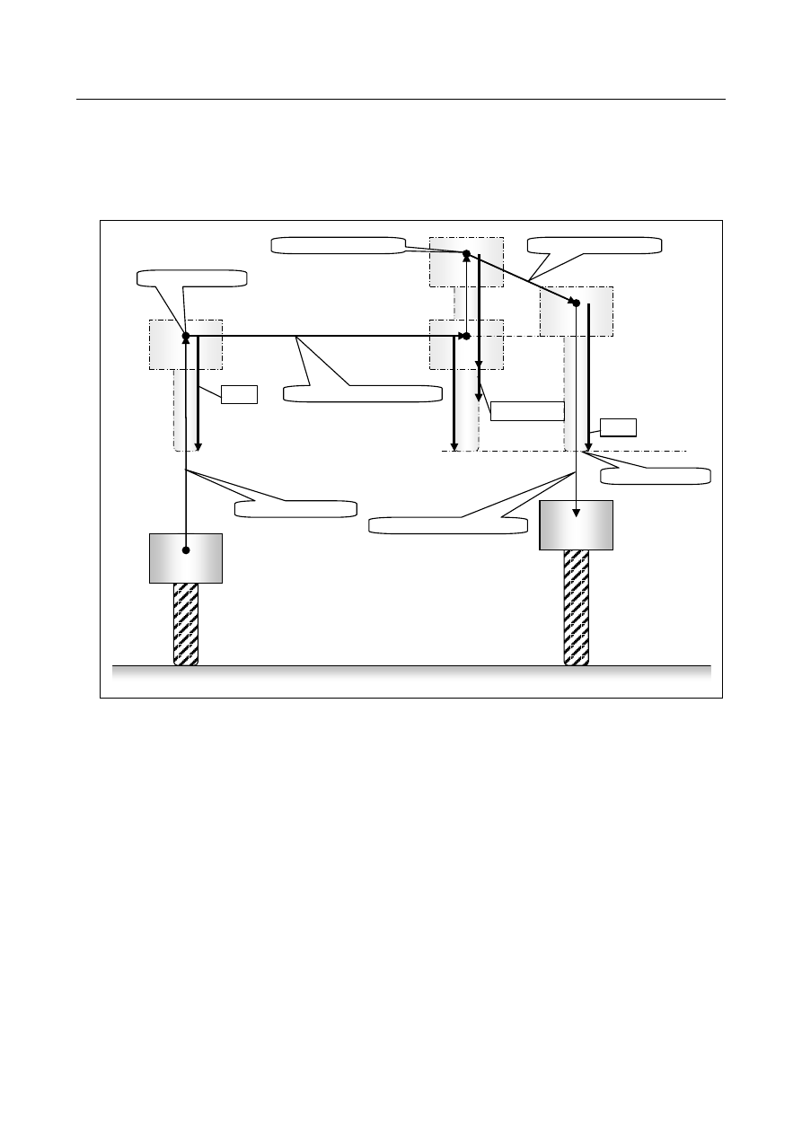
Example-1 (When the bit 6 (TNR) of parameter No.7002 is set to 0): 
Assuming that the compensation  value is updated from OFS

1

  to OFS

2

  after exchanging the tool at the 

manual retract position. When the recovery operation is started, the updated compensation value OFS

is 

used, the tip point of new tool and old tool is the same position in the retract position. (Refer to the figure 
Fig. 5.8.1 (a)) 


1.Retract Operation


2. Manual retract Operation


Retract Point


OFS

1


OFS

2


Manual retract Point


3.Recovery Operation


In case of TNR=0


OFS

1

OFS

2


4.Re-positioning Operation


Fig. 5.8.1 (a) 


B-64693EN-1/01


5. AUTOMATIC OPERATION


- 939 - 

Example-2 (When the bit 6 (TNR) of parameter No.7002 is set to 1): 
Assuming that the compensation  value is updated from OFS

1

  to OFS

2

  after exchanging the tool in the 

manual retract position. When the recovery operation is started, the updated compensation value OFS

2

 is 

not used. After re-positioning operation, the updated compensation  value OFS

2

  is used (Refer to the 

figure Fig. 5.8.1 (b)) 


1.Retract Operation


2. Manual retract Operation


Retract Point


OFS

1


OFS

2


Manual retract Point


3.Recovery Operation


In case of TNR=1


OFS

1

OFS

2


4.Re-positioning Operation


Fig. 5.8.1 (b) 


Parameter 


#7 

#6 

#5 

#4 

#3 

#2 

#1 

#0 

7002 


TRO 

TNR 


[Input type]  Parameter input 


[Data type]  Bit path 


#6  TNR

  When the updated compensation value in the tool retract and recover function is effective 

(the bit 7 (TRO) of parameter No.7002 is set to 1) 
0:  The updated compensation value is effective in the recovery operation. 
1:  The updated compensation value is effective in the re-positioning operation. 


#7  TRO 

When the compensation  value is updated while the tool retract and recover function is 
executing, 
0:  The updated compensation value is invalid. 
1:  The updated compensation value is effective. 
 

5. AUTOMATIC OPERATION


B-64693EN-1/01


- 940 - 

Notes 

NOTE 

1  The compensation considered by this function is as follows. Neither the cutter 

compensation nor the tool nose radius compensation is considered. 
Machining system : Tool length compensation G43/G44 (wear/geometry), 
 

  Tool Offset G43.7/G44.7 (wear /geometry) 

Lathe system 

: When the Extended Tool Selection is not used (the bit 3 

(TCT) of parameter No.5040 is set to 0) 
Tool compensation T code (wear /geometry) 


  When the Extended Tool Selection is not used (the bit 3 

(TCT) of parameter No.5040 is set to 1)   


  Tool length compensation G43/G44 (wear /geometry), 


  Tool Offset G43.7/G44.7 (wear /geometry) 

2  The compensation value can be changed only in the retract position or the 

manual retract position. 

3  When the tool length compensation B is used, the vertical axis against the plane 

from which the tool retract and recover is executed is compensated. This plane is 
not a same plane when G43/G44 is instructed (In case machining system) 

4  When the tool length compensation C is used and G43 or G44 is commanded, 

the compensated axis is indefinite. Therefore this function cannot be used in this 
case. 

5  This function cannot be used during the movement to the reference position by 

the G28/G30 command or the G53 command is executing. 


5.9 

MANUAL INTERVENTION AND RETURN 

Overview 

If you use feed hold to stop the tool from moving an axis during automatic operation and restarts the tool 
after manual intervention, for example, for checking a cutting surface, the tool can resume automatic 
operation after automatically returning to the pre-intervention position. 
This function is optional. 
 

Explanation 

Setting bit 0 (MIT) of parameter No. 7001 enables manual intervention and return. 
The sequence of manual intervention and return is as follows: 
 
1. 

The N1 block cuts a workpiece. 


Tool 

N1 

N2 


2. 

Stop the tool using feed hold in the middle of the N1 block (at point A). 


N2 

N1 

Point A 


B-64693EN-1/01


5. AUTOMATIC OPERATION


- 941 - 

3. 

Retract the tool to point B by manual operation, then restart the machine. 


N2 

N1 

Point A 

Point B 

Manual intervention 


4. 

After the tool automatically returns to point A by non-linear interpolation type positioning at the dry 
run feedrate, the remaining move command of the N1 block is executed. 


N2 

N1 

Point A 

Point B 


Return (Non-linear interpolation type positioning) 


  WARNING 

Manual intervention must be performed correctly with meticulous care, following 
the machining direction and the shape of the workpiece, not to damage the 
workpiece, machine, and/or tool. 


N2 

N1 

Point A 

Point B 

Return (Non-linear interpolation type positioning) 

N2 

N1 

Point A 

Point B 

Manual intervention 


  - 

Manual absolute on/off 

In manual absolute off mode, the tool does not return to the stop position. Instead, the tool moves 
according to the manual absolute on/off function. 
 

  - 

Return feedrate 

For the return operation, the dry run feedrate is used, and the jog feedrate override function is enabled. 
When manual rapid traverse selection signal RT <G019.7> is 1, the return feedrate is not dry run feedrate 
but rapid traverse rate. 
 

  - 

Return operation 

Return operation is performed according to non-linear interpolation type positioning. 
 

5. AUTOMATIC OPERATION


B-64693EN-1/01


- 942 - 

  - 

Single block 

If the single block stop switch is on during return operation, the tool stops at the stop position once and 
restarts movement when cycle start is executed again. 
 

  - 

Cancellation 

If a reset, alarm, or emergency stop occurs during manual intervention or return operation, the manual 
intervention and return function is cancelled. 
 

  - 

MDI mode 

The manual intervention and return function can be used in the MDI mode as well. 
 

  - 

Relation to other functions 

In other functions such as canned cycle, the manual intervention and return function is effective. 
 

  - 

PMC axis control 

If intervention is performed under PMC axis control after feed-holding  of automatic operation, return 
operation does not apply to the axis moving under PMC axis control when the return operation starts. 
If the return operation is started with the axis under PMC axis control being stopped after having 
completed the PMC axis control command, however, the return operation is performed by the amount of 
movement by PMC axis control. 
When PMC axis control is used for an axis unrelated to the program command, set bit 0 of parameter No. 
10410 to 1 to exclude the axis completely from return operation by the manual intervention and return 
function. 
 

Parameter 


#7 

#6 

#5 

#4 

#3 

#2 

#1 

#0 

7001 


MIT 


[Input type]  Parameter input 


[Data type]  Bit path 


#0  MIT

  Manual intervention and return function is: 

0: 

Disabled. 

1: 

Enabled. 


#7 

#6 

#5 

#4 

#3 

#2 

#1 

#0 

10410 


NRT 


[Input type]  Parameter input 


[Data type]  Bit axis 


#0  NRT

  In tool retract and recover or manual intervention and return, the axis is: 

0: 

Subject to tool retract and recover or manual intervention and return. 

1: 

Not subject to tool retract and recover or manual intervention and return. 


Alarm and message 

Number 

Message 

Description 

PS5219 

CAN NOT RETURN 

Manual intervention and return cannot be performed 
during execution of 3-dimensional coordinate system 
conversion, tilted working plane indexing. 


B-64693EN-1/01


5. AUTOMATIC OPERATION


- 943 - 

Limitations 

  - 

Enabling/disabling of manual intervention and return function 

Manual intervention and return function is enabled in the feed hold state (feed hold lamp signal 
SPL<Fn000.4> is set to "1"). 
Manual intervention and return function is disabled in automatic operation stop state (single block stop, 
feed hold stop with no travel distance remaining, etc.)  and the operation is performed according to the 
manual absolute on/off function. 
 

  - 

Offset 

When the tool is replaced using manual intervention for a reason such as tool damage, even if the amount 
of offset is changed when restarting in the middle of the interrupted block, the change is not reflected in 
machining. 
 

  - 

Machine lock, mirror image, and scaling 

When performing manual intervention and return, never use the machine lock, mirror image, or scaling 
function. 
 

  - 

3-dimensional coordinate system conversion, tilted working plane indexing 

Alarm PS5129 is issued when manual intervention and the return is attempted during execution of 
3-dimensional coordinate system conversion, tilted working plane indexing. 
 

  - 

Parking 

Do not switch the parking signal during manual intervention and return (for example, after feed hold stop). 
The tool may not return in the right position when the parking signal is switched during manual 
intervention and return. 
 

  - 

Manual intervention and return by multi-path system 

If cycle start is executed at the same time on two or more paths in a multi-path system, the path that 
performed manual intervention does return operation. However, the path that did not perform manual 
intervention restarts processing without doing return operation. 
 

Axis for which return operation is not performed 

When the axis is in the following conditions, return operation of the axis is not performed. 

Spindle positioning 

Tapping 

Slave axis of axis synchronous control 

Slave axis of synchronous control 

Spindle control by servo motor 

Polygon axis 


NOTE 

   Under synchronous control, manual intervention and return can be performed for 

the slave axis only when bit 2 (PKUx) of parameter No. 8162 is 1 and the master 
axis is parking. 


Feed hold during return operation 

Feed hold is not effective during return operation. 
 

5. AUTOMATIC OPERATION


B-64693EN-1/01


- 944 - 

5.10 

RETRACE 

M


Overview 

The tool can retrace the path along which the tool has moved so far (reverse execution). Furthermore, 
the tool can move along the retraced path in the forward direction (forward reexecution). After forward 
reexecution is performed until the tool reaches the position at which reverse execution started, 
machining is continued as programmed. 


NOTE 


This function is optional. 


Procedure 

  - 

Forward execution 

 reverse execution 

To perform forward execution of a program, set the reverse execution signal RVS<Gn007.0> to “0”, then 
perform a cycle start operation. If the reverse execution signal RVS is set to “1”, reverse execution or the 
end of reverse execution results. 
To perform reverse execution of a program, use one of the following methods: 
1) 

Set the reverse execution signal RVS to “1” during forward execution of a block. 

2) 

Perform a single block stop operation during forward execution, then set the reverse execution signal 
RVS to “1”. 

3) 

Perform a feed hold stop operation during forward execution, then set the reverse execution signal 
RVS to “1”. 

 
When method 1) is used, reverse execution starts after the end of the block being executed (after 
execution up to the single block stop position). Reverse execution does not start as soon as the reverse 
execution signal RVS is set to on. 


Fig. 5.10 (a) 

 
When method 2) is used, performing a cycle start operation starts reverse execution from the position at 
which a single block stop takes place. 


Single block stop 
Reverse execution signal RVS = 1 
Cycle start 

Cycle start (start of forward execution) 

Start of reverse execution 

Forward 
Reverse 


Fig. 5.10 (b) 

 
When method 3) is used, performing a cycle start operation starts reverse execution from the position at 
which a feed hold stop takes place. 


Forward 
Reverse 

Reverse execution signal RVS = 1 
 

Cycle start (start of forward execution) 

Start of reverse execution 


B-64693EN-1/01


5. AUTOMATIC OPERATION


- 945 - 


Feed hold stop 
Reverse execution signal RVS = 1 
Cycle start 

Cycle start (start of forward execution) 

Start of reverse execution 

Forward 
Reverse 


Fig. 5.10 (c) 


  - 

Reverse execution 

 forward reexecution 

To perform forward reexecution of a program, use one of the following three methods: 
1) 

Set the reverse execution signal RVS to 0 during reverse execution of a block. 

2) 

Set the reverse execution signal RVS to 0 after a single block stop takes place during reverse 
execution. 

3) 

Set the reverse execution signal RVS to 0 after a feed hold stop takes place during reverse execution. 

 
When method 1) is used, forward reexecution starts after the block being executed ends (after execution 
up to the position at which a single block stop takes place). Forward reexecution does not start as soon as 
the reverse execution signal RVS is set to 0. 


Cycle start (start of forward execution) 

Start of forward                    Reverse execution signal RVS = 0 
reexecution 

Forward 
Reverse 
Forward   
reexecution 

Start of reverse execution 


Fig. 5.10 (d) 

 
When method 2) is used, performing a cycle start operation starts forward reexecution from the position 
at which a single block stop takes place. 


Cycle start (start of forward execution) 


Start of forward reexecution 
 

Forward 
Reverse 
Forward reexecution 
 

Start of reverse execution 

Restart of forward execution 


Fig. 5.10 (e) 

 
When method 3) is used, performing a cycle start operation starts forward reexecution from the position 
at which a feed hold stop takes place. 


Feed hold stop 
Reverse execution signal RVS = 0 
Cycle start 

Cycle start (start of forward execution) 

Start of forward reexecution 

Forward 
Reverse 
Forward reexecution 

Start of reverse execution 


Fig. 5.10 (f) 


  - 

Reverse execution 

 end of reverse execution 

 forward reexecution 

When a block to be executed is no longer present during reverse execution (when reverse execution has 
been performed up to the block where forward execution started, or when forward execution has not yet 
been performed), the reverse execution end state is entered, and operation stops. 


Content      ..     121      122      123      124     ..