FANUC Series 0i-MODEL F Plus. CONNECTION MANUAL (FUNCTION) - page 122
 

  Index      Manuals     FANUC Series 0i-MODEL F Plus. CONNECTION MANUAL (FUNCTION) B-64693EN-1/01


Search            copyright infringement  


Content      ..     120      121      122      123     ..


FANUC Series 0i-MODEL F Plus. CONNECTION MANUAL (FUNCTION) - page 122


5. AUTOMATIC OPERATION


B-64693EN-1/01


- 930 - 

5.8 

TOOL RETRACT AND RECOVER 

Overview 

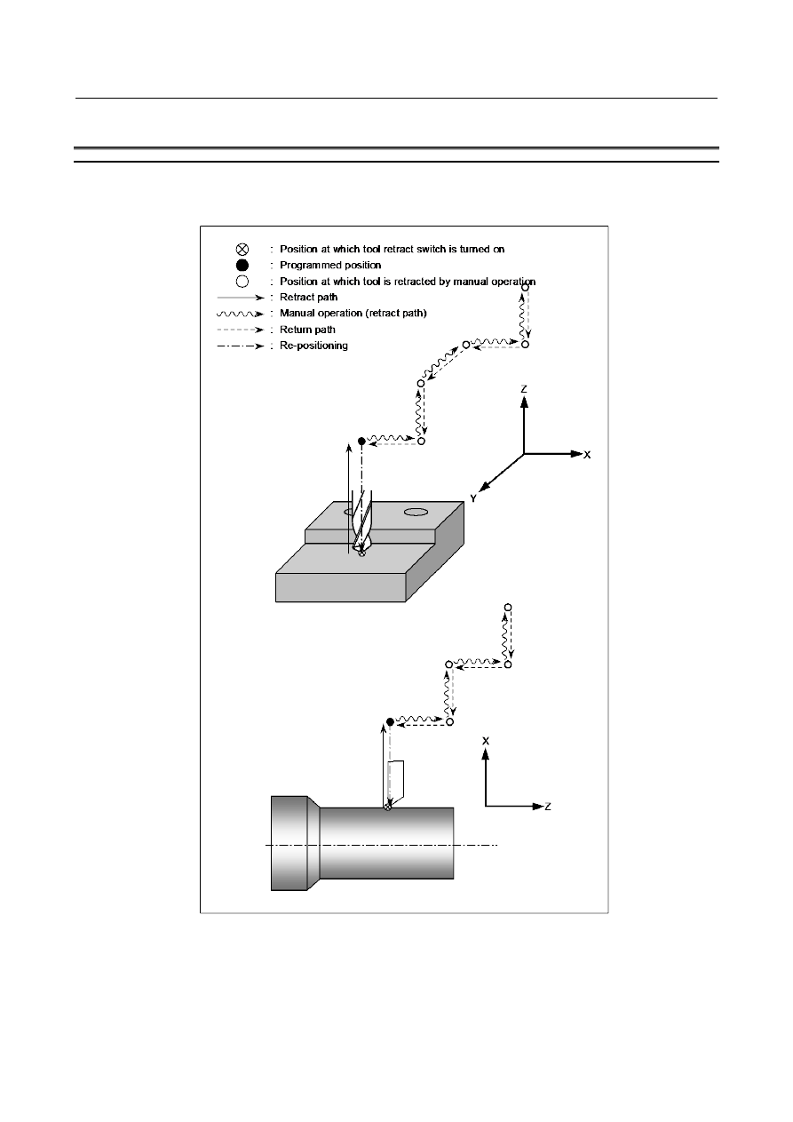
The tool can be retracted from a workpiece to replace the tool, if damaged during machining, or to check 
the status of machining. Then, the tool can be returned to restart machining efficiently. 


Fig. 5.8 (a) Path of tool retract and recover for milling machining 


  - 

Basic procedure for tool retract and recover 

(1)  When tool retraction signal TRESC <Gn059.0>, which is an input signal from the PMC, is set to 1 

during automatic operation, in the automatic operation stopped state, or in the automatic operation 
halted state, the tool is retracted by a specified distance. This operation is called retraction. The 
position at which the retraction is completed is called the retract position. 

B-64693EN-1/01


5. AUTOMATIC OPERATION


- 931 - 


The tool is retracted by linear interpolation at the minimum feedrate among the parameter (No.7042) 
values of moving axes.   
If a block is being executed halfway when the TRESC signal is set to “1” during automatic operation, 
the execution of the block is interrupted immediately, then retraction is performed. After the 
retraction is completed, the automatic operation is halted. If G10.6 is not programmed, retraction 
does not take place, block execution is interrupted, and the automatic operation is halted or stopped. 
The distance of retraction can also be specified in parameter No. 7041. 
When the TRESC signal is set to “1”, it is said that the tool retraction mode is entered. 
The tool retraction mode involves all of retraction, manual retraction, recovery, and re-positioning 
operations. 
When the tool retraction mode is entered, tool retraction mode signal TRACT  <Fn092.3>  is set to 
“1”, notifying the PMC that the tool retraction mode is set. 
When the tool starts moving to retract, tool retraction axis movement signal TRMTN <Fn092.4> is 
set to “1”. When the tool is stopped at the retract position, TRMTN is set to “0”, and tool 
retraction/return completion signal TRSPS <Fn092.5> is set to “1”. 


Automatic operation 
mode 

Tool retraction signal 
(TRESC)


Tool retraction mode 
signal (TRACT) 

Tool retraction axis 
movement signal (TRMTN) 

Move in retract 

Tool retraction/return 
completion signal (TRSPS) 


Fig. 5.8 (b) Timing chart of retraction operation (when movement is involved) 

 
(2)  Change the mode to the manual mode, and move the tool by a manual operation (jog feed, 

incremental feed, manual handle feed) for a purpose such as the purpose of changing the tool. This 
operation is called manual retraction. The CNC automatically records the retract path of the tool. Up 
to 20 points on the tool retract path are recorded automatically. When the tool is retracted manually, 
the TRSPS signal is set to “0”. While the tool is moving along an axis by manual operation, the 
TRMTN signal is “0”. 


Automatic operation mode 

Manual operation mode 

Tool retraction mode signal 
(TRACT) 

Tool retraction axis   
movement signal 
(TRMTN) 


Manual axis movement


Tool retraction/return completion signal   

(TRSPS)


"1" when the retraction mode is maintained


"0" during retraction


Fig. 5.8 (c) Timing chart of manual retraction 


5. AUTOMATIC OPERATION


B-64693EN-1/01


- 932 - 

NOTE 


If the path number is 5 or over, the maximum number of record points on the 
tool retract path is 10. 

 
(3)  Restore the automatic operation mode, and set tool return signal TRRTN  <Gn059.1>  to “1” then 

back “0”. The CNC then reverses the tool along the path of the manual movement to return the tool 
to the retract position. This operation is called recovery. When the tool starts moving for recovery, 
TRMTN is set to “1”. Upon completion of the recovery to the retract position, TRSPS is set to “1”. 
The recovery is performed at the feedrate specified by parameter No.7042 for each axis. 


Automatic operation mode 

Manual operation mode 

Move in recovery 

Tool retraction axis 
movement signal 
(TRMTN) 


Tool return signal 

(TRRTN) 

Tool return completion 
signal (TRSPS) 


Fig. 5.8 (d) Timing chart of recovery (when the tool returns to the retract position   

without performing single block stop or feed hold stop during recovery) 

 
(4)  When a cycle start is directed at the retract position, the tool first moves to a position at which tool 

retraction signal TRESC was set to “1”. This operation is called re-positioning. As re-positioning 
starts, tool retraction/return completion signal TRSPS is set to “0”. During movement for 
re-positioning, tool retraction axis movement signal TRMTN is “1”. 
The re-positioning movement is made by linear interpolation at the minimum feedrate among the 
parameter (No.7042) values of moving axes. 
Upon completion of the re-positioning, tool retraction mode signal TRACT is set to “0”, notifying 
the PMC that the tool retraction mode ends. The subsequent operation varies depending on the 
automatic operation state present when the tool retraction mode was entered as follows: 
<1>  When the tool retraction mode was entered during automatic operation, the interrupted 

automatic operation is restarted continuously after re-positioning is completed. 

<2>  When the tool retraction mode was entered from the automatic operation stopped state or 

automatic operation halted state, the automatic operation stopped state or automatic operation 
halted state is once entered, respectively, after re-positioning is completed. Then, directing a 
cycle start restarts automatic operation. 

B-64693EN-1/01


5. AUTOMATIC OPERATION


- 933 - 


Fig. 5.8 (e) Timing chart of re-positioning (when movement is involved) 


NOTE 

1 If negative value or zero is set in parameter (No.7042) of moving axes, retract, 

recovery and re-positioning are performed at the dry run feedrate.   

2 Manual feedrate override signal is effective for the feedrate of parameter 

(No.7042). 


Tool retract and recover for threading 

Tool retract and recover for threading is different from ordinary tool retract and recover as follows   
(1)  During retraction, chamfering is performed between the specified retraction axis and threading axis. 

Furthermore, in this state, tool retraction axis movement signal TRMTN is not set to “1” 

(2)  After retraction, one block that does not specify threading is executed and the tool stops. 
(3)  When the major axis for threading is specified as the retraction axis, retraction is not performed by 

turning the TOOL WITHDRAW switch on. In this case, after a block that does not specify threading 
is executed, an alarm PS0429, “ILLEGAL COMMAND IN G10.6” is issued and the tool stops. 

(4)  As repositioning, the tool is returned to the position specified in the first block that does not specify 

threading. 


5. AUTOMATIC OPERATION


B-64693EN-1/01


- 934 - 

NOTE 

3 In threading cycle and multiple threading cycle, tool retract and recover is invalid.   
4 In circular threading, tool retract and recover is invalid.   
5 When dry run is executed, tool retract and recover for threading is invalid. 
6 In continuous threading blocks other than last threading block, if retract start at a 

location near the block end, retract is executed in multiple blocks. 


Location where the tool 

retract signal is set to “1” 

Tool path with tool retract execution 

Tool path without tool retract execution 

Retract in multiple blocks 

Threading block 

Threading block 


7 In taper threading, specify the retract position as the tool does not collide the 

workpiece surely because the tool might collide depending on specification of 
retract position as following figure.   


The location where the tool retraction 

signal TRESC is set to 1, 

The tool path with tool retract 

The tool path without tool retract 

Taper threading block 

Retract position 

The workpiece might collide because the tool path with retract does not pass the retract 

direction side than the tool path without retract. 


Signal 

Tool retraction signal TRESC<Gn059.0> 

    [Classification]  Input signal 
   

[Function]  Tool retraction mode is selected. 


  [Operation]  When this signal is turned to “1”, the CNC  retracts the tool by a pre-programmed 

distance. 


Tool retraction mode signal TRACT<Fn092.3> 

    [Classification]  Output signal 
 

  [Function]  This signal reports that tool retraction mode is set. When the CNC  is reset while the 

signal is “1”, the signal is turned to “0”, and tool retraction mode is canceled. 

    [Output cond.]  The signal is turned to “1” when: 

Tool retraction mode is selected. 

The signal is turned to “0” when: 

Tool retraction mode is not selected. 


B-64693EN-1/01


5. AUTOMATIC OPERATION


- 935 - 

Tool return signal TRRTN<Gn059.1> 

    [Classification]  Input signal 
 

  [Function]  In tool retraction mode, a tool that has been retracted manually along an axis is returned 

to the retract position along the same axis. 


[Operation]  When this signal is turned from “1” to “0”, the CNC traces back the path of the manually 

moved tool to automatically return the tool to the retract position. 


Tool retraction axis movement signal TRMTN<Fn092.4> 

    [Classification]  Output signal 
 

[Function]  This signal reports that the tool is moving along an axis during retraction, recovery, or 

re-positioning. 


[Output cond.]  The signal is turned to “1” when: 

The tool moves along an axis during retraction, recovery, or re-positioning. 

The signal is turned to “0” when: 

The tool does not move along any axis during retraction, recovery, or re-positioning. 


Tool return completion signal TRSPS<Fn092.5> 

    [Classification]  Output signal 
   

[Function]  This signal reports that the tool is in the retract position in tool retraction mode. When 

this signal is “0”, re-positioning cannot be performed by pressing the cycle start button. 

    [Output cond.]  The signal is set to “1” when: 

Retraction has been completed. 

The tool has been returned to the retract position. 

The signal is set to “0” when: 

The tool is not in the retract position in tool retraction mode. 


Signal address 


#7 

#6 

#5 

#4 

#3 

#2 

#1 

#0 

Gn059 


TRRTN 

TRESC 


#7 

#6 

#5 

#4 

#3 

#2 

#1 

#0 

Fn092 


TRSPS 

TRMTN 

TRACT 


Parameter 


#7 

#6 

#5 

#4 

#3 

#2 

#1 

#0 

7040 


TRC 

RPS 

TRS 

TRI 


[Input type]  Parameter input 


[Data type]  Bit path 


#0  TRI

  The G10.6 command for tool retract and return is: 

0: 

Assumed to be an absolute or incremental programming according to the absolute or 
incremental programming mode. 

1: 

Always assumed to be an incremental programming. 


#1  TRS

  After the completion of repositioning in tool retract and return: 

0: 

Automatic operation is restarted. 

1: 

Operation stops when the single block switch is on. When a cycle start is executed 
again, automatic operation is started. 


5. AUTOMATIC OPERATION


B-64693EN-1/01


- 936 - 


#2  RPS

  When the tool retract signal TRESC  <Gn059.0> is set to “1” after G10.6 is specified 

alone: 
0: 

The tool is not retracted. 

1: 

The tool is retracted with the value set for parameter No. 7041 or 11261 used as the 
incremental retraction distance. 


#3  TRC

  When automatic operation is restarted after the tool retract and return is executed during 

the execution of a drilling canned cycle: 
0: 

Machining of the same cycle is performed again (the same drilling is performed). 

1: 

Machining of the next drilling cycle is performed (the next drilling is performed). 


7041 


Retraction distance in tool retract and return 


[Input type]  Setting input 


[Data type]  Real axis 


[Unit of data]  mm, inch, deg (input unit) 

[Min. unit of data]  Depend on the increment system of the applied axis 
[Valid data range]  9 digit of minimum unit of data (refer to standard parameter setting table (A))   

(When the increment system is IS-B, -999999.999 to +999999.999) 
This parameter sets the retraction distance used when G10.6 is specified alone for the tool 
retract and return. The tool is retracted by the distance set for this parameter in the 
incremental mode. This data is valid only when bit 2 (RPS) of parameter No. 7040 is set 
to 1. 


7042 


Feedrate for each axis in tool retract and recover 


[Input type]  Parameter input 


[Data type]  Real axis 


[Unit of data]  mm/min, inch/min, deg/min (machine unit) 

[Min. unit of data]  Depend on the increment system of the applied axis 
[Valid data range]  Refer to the standard parameter setting table (C) 

Set the feedrate for each axis in tool retract and recover. The recovery is performed at the 
feedrate specified by this parameter. The retract and repositioning are performed at the 
minimum feedrate among the parameter values of moving axes.  Furthermore, if 
maximum number of record point in manual retract is exceeded, the tool move to last 
record point by linear interpolation at the minimum feedrate among the parameter values 
of moving axes.  Manual feedrate override signal is effective for the feedrate of this 
parameter. 


#7 

#6 

#5 

#4 

#3 

#2 

#1 

#0 

10410 


NRT 


[Input type]  Parameter input 


[Data type]  Bit axis 


#0  NRT

  In tool retract and recover or manual intervention and return, the axis is: 

0: 

Subject to tool retract and recover or manual intervention and return. 

1: 

Not subject to tool retract and recover or manual intervention and return. 


Limitation 

Tool retract and recover cannot be performed along axes that are in the modes below. 

Superimposed control 


B-64693EN-1/01


5. AUTOMATIC OPERATION


- 937 - 

Warning 

  WARNING 


The retraction axes and retraction distances specified with G10.6 need to be 
changed in appropriate blocks depending on the figure to be machined. An 
incorrectly specified retraction distance may damage a workpiece, the machine, 
or the tool. So, be very careful when specifying a retraction distance. 


Alarm and message 

Number 

Message 

Description 

DS0310 

NOT ON RETURN POINT 

The return position recorded during retraction is not reached 
during recovery. The position may be displaced during recovery 
due to a machine lock or mirror image. 
Perform the operation again after making a reset. 

PS0015 

TOO MANY SIMULTANEOUS 
AXES 

A move command was specified for more axes than can be 
controlled by simultaneous axis control. 
Either add on the simultaneous axis control extension, or divide 
the number of programmed move axes into two blocks. 

PS0429 

ILLEGAL COMMAND IN G10.6 

When retraction was started in the threading block, the retract 
command was performed in the longitudinal direction of the 
threading. 


Reference item 

Manual name 

Item name 

OPERATOR’S MANUAL (B-64694EN) 

Tool retract and recover 


5.8.1 

Improvement of Tool Compensation for


Tool Retract and 

Recover 

Outline 

In this function, when the recovery operation or re-positioning operation is started, the updated 
compensation value is used. Therefore the restart operation is performed with the updated compensation 
value. 
 

Explanation 

If this function is effective (the bit 7 (TRO) of parameter No.7002 is set to 1), when the recovery 
operation or re-positioning operation is started, the updated compensation  value is used and the restart 
operation is performed with the updated compensation value. Thus, if the compensation value is updated 
after exchanging the tool  at the manual retract position or the retract position, the tip point of tool 
becomes the same position as it of before exchanging tool in the restart operation thereafter. 
 
The operation that updated  compensation  value is effective can be selected  by  the bit 6 (TNR) of 
parameter No.7002. 


Content      ..     120      121      122      123     ..