FANUC Series 0i-MODEL F Plus. CONNECTION MANUAL (FUNCTION) - page 78
 

  Index      Manuals     FANUC Series 0i-MODEL F Plus. CONNECTION MANUAL (FUNCTION) B-64693EN-1/01


Search            copyright infringement  


Content      ..     76      77      78      79     ..


FANUC Series 0i-MODEL F Plus. CONNECTION MANUAL (FUNCTION) - page 78


2. PREPARATIONS FOR OPERATION


B-64693EN-1/01


- 578 - 

When an unexpected disturbance torque is detected  on an axis, only the movements on 
those axes that belong to the same group as the axis are stopped. 
If 0 is set for an axis, the movement  on the axis  is stopped when an unexpected 
disturbance torque is detected on any other axis. 
This parameter is valid when bit 5 (ANA) of parameter No. 1804 is set to 1. 


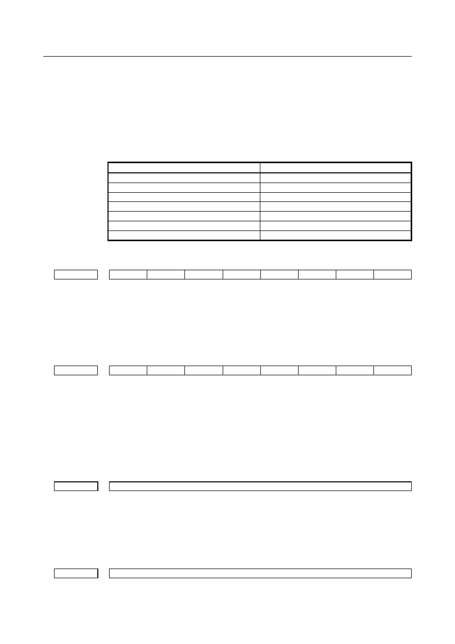
[Example]  When the settings indicated below are made, and an unexpected disturbance torque  is 

detected on the 6th axis, the movements on the 2nd axis, 4th axis, 6th axis, and 7th axis 
are stopped. When an unexpected disturbance torque is detected  on the 4th axis, the 
movements on the 4th axis and the 7th axis are stopped. 


Parameter No. 1881 

Setting value 

(1st axis) 

(2nd axis) 

(3rd axis) 

(4th axis) 

(5th axis) 

(6th axis) 

(7th axis) 


  - 

Servo axis 


#7 

#6 

#5 

#4 

#3 

#2 

#1 

#0 

2015 


TDOUT 


[Input type]  Parameter input 


[Data type]  Bit axis 


#5  TDOUT

  Select output to the check board (for each axis) 

0: 

Output the torque command to the check board. 

1: 

Output the estimated load torque to the check board. 


#7 

#6 

#5 

#4 

#3 

#2 

#1 

#0 

2016 


ABNT 


[Input type]  Parameter input 


[Data type]  Bit axis 


#0  ABNT

  Unexpected disturbance torque detection function (for each axis) is 

0: 

Disabled 

1: 

Enabled 


When using the unexpected disturbance torque detection alarm function and 
estimated disturbance torque output function, enable the unexpected disturbance 
torque detection function. 


2050 


Velocity control observer 


[Input type]  Parameter input 


[Data type]  Word axis 


[Valid data range]  0 to 32767 

Be sure to set this parameter to 3559. 
When using the velocity loop observer (by setting bit 2 (OBEN) of parameter No. 2003 to 

1), set 956 in this parameter.     


2051 


Velocity control observer 


[Input type]  Parameter input 

B-64693EN-1/01


2. PREPARATIONS FOR OPERATION


- 579 - 


[Data type]  Word axis 


[Valid data range]  0 to 32767 

Be sure to set this parameter to 3329. 
When using the velocity loop observer (by setting bit 2 (OBEN) of parameter No. 2003 to 
1), set 510 in this parameter.     


2103 


Retraction distance upon the detection of an unexpected disturbance torque 


[Input type]  Parameter input 


[Data type]  Word axis 


[Unit of data]  Detection unit 


[Valid data range]  0 to 32767 

This parameter specifies the distance by which the tool is to be retracted, by reversing the 
motor, if an unexpected disturbance torque is detected. 
When the motor is rotating at low speed, however, the tool may be retracted too far. To 
prevent this, the motor is stopped, instead of being reversed, while the specified feedrate 
is less than the value listed in the table below.   
When this parameter is set to value A, the detection of an unexpected disturbance torque 
causes the tool to be retracted in the reverse direction by the distance A, then stopped, if 
the specified feedrate is equal to or greater than the value listed below. 
 

Detection unit 

Feedrate 


10 

µ


A / 

0.8  mm/ min 


µ


A / 

mm/ min 


0.1 

µ


A / 

80 

mm/ min 


0.01 

µ


A /  800 

mm/ min 


0.001 

µ


A /  8000 

mm/ min 

When this parameter is set to 0, the motor stops immediately upon the detection of 
unexpected disturbance torque.   
 

2104 


Threshold for unexpected disturbance torque detection alarm 


[Input type]  Parameter input 


[Data type]  Word axis 


[Unit of data]  Torque command unit 


[Valid data range]  0 to 7282 (The maximum motor torque is 7282, regardless of the motor type.)   

This  parameter specifies the threshold load torque at which an unexpected disturbance 
torque detection alarm is issued. 
Monitor the load torque by setting bit 5 (TDOUT) of parameter No. 2015 to 1 then, for 
this parameter No. 2104, set a value larger than the maximum monitored torque. An 
output of 4.4 V is equivalent to 7282 in the units of this parameter. 


2142 


Threshold for unexpected disturbance torque detection alarm for rapid traverse 


[Input type]  Parameter input 


[Data type]  Word axis 


[Unit of data]  Torque command unit 

[Valid data range]  0 to 7282 (The maximum motor torque is 7282, regardless of the motor type.)   

This parameter specifies the threshold load torque at which an unexpected disturbance 
torque detection alarm is issued. 
Monitor the load torque by setting bit 5 (TDOUT) of parameter No. 2015 to 1 then, for 
this parameter No. 2104, set a value larger than the maximum monitored torque. An 
output of 4.4 V is equivalent to 7282 in the units of this parameter. 
This parameter is enabled when bit 3 (ABG0) of parameter No. 2200 = 1. 


2. PREPARATIONS FOR OPERATION


B-64693EN-1/01


- 580 - 


#7 

#6 

#5 

#4 

#3 

#2 

#1 

#0 

2200 


ABG0 


[Input type]  Parameter input 


[Data type]  Bit axis 


#3  ABG0

  The unexpected disturbance torque detection function for cutting or rapid traverse is: 

0: 

Disabled. 

1: 

Enabled. 

When this function is disabled, the threshold value during cutting feed is used (parameter 
No. 2104). 


#7 

#6 

#5 

#4 

#3 

#2 

#1 

#0 

2215 


ABDSW 


[Input type]  Parameter input 


[Data type]  Bit axis 


#5  ABDSW

  The Unexpected disturbance torque detection function for a specified axis: 

0: 

Cannot be disabled. 

1: 

Can be disabled. 


  - 

Parameters for spindle 


#7 

#6 

#5 

#4 

#3 

#2 

#1 

#0 

4015 


SPLDMT 


[Input type]  Parameter input 


[Data type]  Bit spindle 


  #1  SPLDMT

  Spindle load torque monitor function 

0: 

The spindle load torque monitor function is disabled.   

1: 

The spindle load torque monitor function is enabled.   


4247 


Magnetic flux compensation time constant for spindle load torque monitor 


[Input type]  Parameter input 


[Data type]  Word spindle 


[Unit of data]  msec 

[Valid data range]  0 to 8192 

This parameter is used to compensate the delay in the generation of magnetic flux in the 
spindle motor relative to the specified value. When 0 is set, it is assumed that the 
generation of magnetic flux is not delayed.   
Standard setting depends of the motor model.   


4248 


Spindle load torque monitor constant 


[Input type]  Parameter input 


[Data type]  Word spindle 

[Valid data range]  0 to 32767 

This constant is determined by the maximum output torque and inertia of the motor. It is 
used for observer processing. 
Standard setting depends of the motor model.   


B-64693EN-1/01


2. PREPARATIONS FOR OPERATION


- 581 - 

4249 


Observer gain 1 for spindle load torque monitor 


[Input type]  Parameter input 


[Data type]  Word spindle 

[Valid data range]  0 to 32767 

Standard setting is 500. 


4250 


Observer gain 2 for spindle load torque monitor 


[Input type]  Parameter input 


[Data type]  Word spindle 

[Valid data range]  0 to 32767 

Standard setting is 500. 


4341 


Threshold for unexpected disturbance torque detection alarm 


[Input type]  Parameter input 


[Data type]  Word spindle 


[Unit of data]  0.01% 

[Valid data range]  0 to 10000 

This parameter specifies the threshold load torque at which an unexpected disturbance 
torque detection alarm is issued for the spindle. Set a percentage (in units of 0.01 %) for 
the maximum output torque of the motor. When 0 is set, no Unexpected disturbance 
torque detection alarm is issued for the spindle.   

Alarm and message 

  - 

Alarm related to servo axis 

Number 

Message 

Description 

SV0409 

DETECT ABNORMAL TORQUE 

An abnormal load was detected on the servo motor, or 
during Cs axis or spindle positioning. 
The alarm can be canceled by RESET. 


  - 

Alarm related to spindle 

Number 

Message 

Description 

SP0754 

ABNORMAL TORQUE 

An abnormal load was detected in a spindle motor. 
The alarm can be canceled by RESET. 


Limitation 

The following limitations are imposed on the abnormal load detection group function: 
<1>  Cannot be used with axes on which inter-path synchronous/composite control or inter-path 

superimposed control is performed. 

<2>  Cannot be used with axes belonging to different paths. 
<3>  Cannot be used with rigid tapping with spindles belonging to different paths. 
<4>  Does not support the inter-path flexible synchronization control function. 
<5>  Does not support the 3-dimensional rigid tapping function. 
 

2.10 

MACHINING CONDITION SELECTION FUNCTION 

Overview 

For AI contour control function, parameters which place importance on feedrate or precision are set and a 
precision level is specified according to the machining condition during machining. By using these 
parameters and level, parameters which satisfy the condition  can automatically be calculated for 
machining. 
 

2. PREPARATIONS FOR OPERATION


B-64693EN-1/01


- 582 - 

Format 

  - 

Changing the precision level by programming 

The precision level can be changed not only by using the precision level selection screen but also by 
programming the following format: 
 

G05.1 Q1 Rx ;   

x : Level (1 to 10) 

 
Also with the format used for, high precision contour control, and AI high precision contour control, the 
precision level can be changed. 
 

G05 P10000 Rx ;   

x : Level (1 to 10) 

G08 P1 Rx ;   

x : Level (1 to 10) 


  CAUTION 


Once a level is specified, it is kept valid even after the AI contour control mode is 
canceled. 


Default level 

By setting the default level for the precision level in parameter No. 11687, a return to the level set in 
parameter No. 11687 is made during power-off or a reset. 
Set the default level to an integer from 1 to 10. 
When the default level is set to 0, the current level is maintained. 
 

Parameter 

11687 


Standard value of precision level when AI contour control is used 


[Input type]  Parameter input 


[Data type]  Byte path 

[Valid data range]  0 to 10 

Set standard value of precision level when AI contour control is used. 
When the power is turned on or the system is reset, the precision level 

:  keeps its value. 

1 to 10  :  becomes the level set to this parameter. 


#7 

#6 

#5 

#4 

#3 

#2 

#1 

#0 

13600 


MSA 


MCR 


[Input type]  Parameter input 


[Data type]  Bit path 


#0  MCR

  When an allowable acceleration  rate adjustment is made with the machining  condition 

selection  function  or (machining  parameter  adjustment  screen, precision level selection 
screen),  parameter No.  1735  for the deceleration  function  based on acceleration  in 
circular interpolation is: 
0: 

Modified. 

1: 

Not modified. 


#7  MSA

  When the machining condition selection function or is used, the acceleration rate change 

time (bell-shaped) (LV1, LV10) is: 

B-64693EN-1/01


2. PREPARATIONS FOR OPERATION


- 583 - 

0: 

Set using parameter Nos. 13612 and 13613. 

1: 

Set using parameter Nos. 13662 and 13663. 


#7 

#6 

#5 

#4 

#3 

#2 

#1 

#0 

13601 


MPR 


[Input type]  Parameter input 


[Data type]  Bit 


NOTE 


When this parameter is set, the power must be turned off before 
operation is continued. 


#0  MPR

  The machining parameter adjustment screen is: 

0: 

Displayed. 

1: 

Not displayed. 

Even if 1 is set in this parameter bit, the precision level selection screen for the machining 
condition selecting function are displayed. 
 

13610 


Acceleration rate for look-ahead acceleration/deceleration before interpolation in AI contour control 

(precision level 1) 


13611 


Acceleration rate for look-ahead acceleration/deceleration before interpolation in AI contour control 

(precision level 10) 


[Input type]  Parameter input 


[Data type]  Real axis 


[Unit of data]  mm/sec

2

, inch/sec

2

, deg/sec

2

 (machine unit) 

[Min. unit of data]  Depend on the increment system of the applied axis 
[Valid data range]  Refer to the standard parameter setting table (D) 

(When the machine system is metric system, 0.0 to +100000.0. When the machine system 
is inch system, machine, 0.0 to +10000.0) 
Each of these parameters sets an acceleration  rate for look-ahead  acceleration/ 
deceleration  before  interpolation  in  AI contour control. Set a value  (precision  level  1) 
with emphasis placed on speed, and a value  (precision  level  10) with emphasis on 
precision. 
 

13612 


Acceleration rate change time (bell-shaped) when AI contour control is used (precision level 1) 


13613 


Acceleration rate change time (bell-shaped) when AI contour control is used (precision level 10) 


[Input type]  Parameter input 


[Data type]  Byte path 


[Unit of data]  msec 

[Valid data range]  0 to 127 

Each of these parameters sets an acceleration rate change time (bell-shaped) in AI contour 
control. Set a value  (precision  level  1) with emphasis placed on speed, and a value 
(precision level 10) with emphasis on precision. 
 

13614 


Allowable acceleration rate change amount for each axis in speed control based on acceleration rate 

change under control on the rate of change of acceleration (precision level 1) 


13615 


Allowable acceleration rate change amount for each axis in speed control based on acceleration rate 

change under control on the rate of change of acceleration (precision level 10) 


2. PREPARATIONS FOR OPERATION


B-64693EN-1/01


- 584 - 


[Input type]  Parameter input 


[Data type]  Real axis 


[Unit of data]  mm/sec

2

, inch/sec

2

, deg/sec

2

 (machine unit) 

[Min. unit of data]  Depend on the increment system of the applied axis 
[Valid data range]  Refer to the standard parameter setting table (D) 

(When the machine system is metric system, 0.0 to +100000.0. When the machine system 
is inch system, machine, 0.0 to +10000.0) 
Each of these parameters sets an allowable acceleration rate change amount per 1 ms for 
each axis in speed control based on acceleration rate change under control on the rate of 
change of acceleration during AI contour control. 
Set a value (precision level 1) with emphasis placed on speed, and a value (precision level 
10) with emphasis on precision. 
 

13616 


Allowable acceleration rate change amount for each axis in speed control based on acceleration rate 

change under control on the rate of change of acceleration in successive linear interpolation operations 

(precision level 1) 


13617 


Allowable acceleration rate change amount for each axis in speed control based on acceleration rate 

change under control on the rate of change of acceleration in successive linear interpolation operations 

(precision level 10) 


[Input type]  Parameter input 


[Data type]  Real axis 


[Unit of data]  mm/sec

2

, inch/sec

2

, deg/sec

2

 (machine unit) 

[Min. unit of data]  Depend on the increment system of the applied axis 
[Valid data range]  Refer to the standard parameter setting table (D) 

(When the machine system is metric system, 0.0 to +100000.0. When the machine system 
is inch system, machine, 0.0 to +10000.0) 
Each of these parameters sets an allowable acceleration rate change amount per 1 ms for 
each axis in speed control based on acceleration rate change under control on the rate of 
change of acceleration  in successive linear interpolation  operations during AI contour 
control. 
Set a value (precision level 1) with emphasis placed on speed, and a value (precision level 
10) with emphasis on precision. 
 

NOTE 

1  For an axis with 0 set in this parameter, parameter No. 13614 and 

No. 13615 (allowable acceleration rate change amount in speed 
control based on acceleration rate change under control on the rate 
of change of acceleration) are valid. 

2  For an axis with 0 set in parameter No. 13614 and No. 13615 

(allowable acceleration rate change amount in speed control based 
on acceleration rate change under control on the rate of change of 
acceleration), speed control based on acceleration rate change is 
disabled, so that the specification of this parameter has no effect. 


13618 


Rate of change time of the rate of change of acceleration in smooth bell-shaped 

acceleration/deceleration before interpolation when AI contour control is used (precision level 1) 


13619 


Rate of change time of the rate of change of acceleration in smooth bell-shaped 

acceleration/deceleration before interpolation when AI contour control is used (precision level 10) 


[Input type]  Parameter input 


[Data type]  Byte path 

B-64693EN-1/01


2. PREPARATIONS FOR OPERATION


- 585 - 


[Unit of data]  % 

[Valid data range]  0 to 50 

Each of these parameters sets the rate (percentage) of the change time of the rate of 
change of acceleration  to the change time of acceleration  rate change in look-ahead 
smooth bell-shaped acceleration/deceleration before interpolation  during  AI contour 
control. 
Set a value (precision level 1) with emphasis placed on speed, and a value (precision level 
10) with emphasis on precision. 
 

NOTE 


When 0 or a value not within the valid data range is set in this 
parameter, look-ahead smooth bell-shaped 
acceleration/deceleration before interpolation is not performed. 


13620 


Allowable acceleration rate when AI contour control is used (precision level 1) 


13621 


Allowable acceleration rate when AI contour control is used (precision level 10) 


[Input type]  Parameter input 


[Data type]  Real axis 


[Unit of data]  mm/sec

2

, inch/sec

2

, deg/sec

2

 (machine unit) 

[Min. unit of data]  Depend on the increment system of the applied axis 
[Valid data range]  Refer to the standard parameter setting table (D) 

(When the machine system is metric system, 0.0 to +100000.0. When the machine system 
is inch system, machine, 0.0 to +10000.0) 
Each of these parameters sets an allowable acceleration rate in AI contour control. Set a 
value (precision level 1) with emphasis placed on speed, and a value (precision level 10) 
with emphasis on precision. 
 

13622 


Time constant for acceleration/deceleration after interpolation when AI contour control is used 

(precision level 1) 


13623 


Time constant for acceleration/deceleration after interpolation when AI contour control is used 

(precision level 10) 


[Input type]  Parameter input 


[Data type]  Word axis 


[Unit of data]  msec 

[Valid data range]  1 to 512 

Each of these parameters sets a time constant  for  acceleration/  deceleration  after 
interpolation  when  AI contour control  is used. Set a value  (precision  level  1) with 
emphasis placed on speed, and a value (precision level 10) with emphasis on precision. 
 

13624 


Corner speed difference when AI contour control is used (precision level 1) 


13625 


Corner speed difference when AI contour control is used (precision level 10) 


[Input type]  Parameter input 


[Data type]  Real axis 


[Unit of data]  mm/min, inch/min, deg/min (machine unit) 

[Min. unit of data]  Depend on the increment system of the applied axis 
[Valid data range]  Refer to the standard parameter setting table (C) 

(When the increment system is IS-B, 0.0 to +999000.0) 


Content      ..     76      77      78      79     ..