FANUC Series 0i-MODEL F Plus. CONNECTION MANUAL (FUNCTION) - page 56
 

  Index      Manuals     FANUC Series 0i-MODEL F Plus. CONNECTION MANUAL (FUNCTION) B-64693EN-1/01


Search            copyright infringement  


Content      ..     54      55      56      57     ..


FANUC Series 0i-MODEL F Plus. CONNECTION MANUAL (FUNCTION) - page 56


1. AXIS CONTROL


B-64693EN-1/01


- 402 - 

1. 

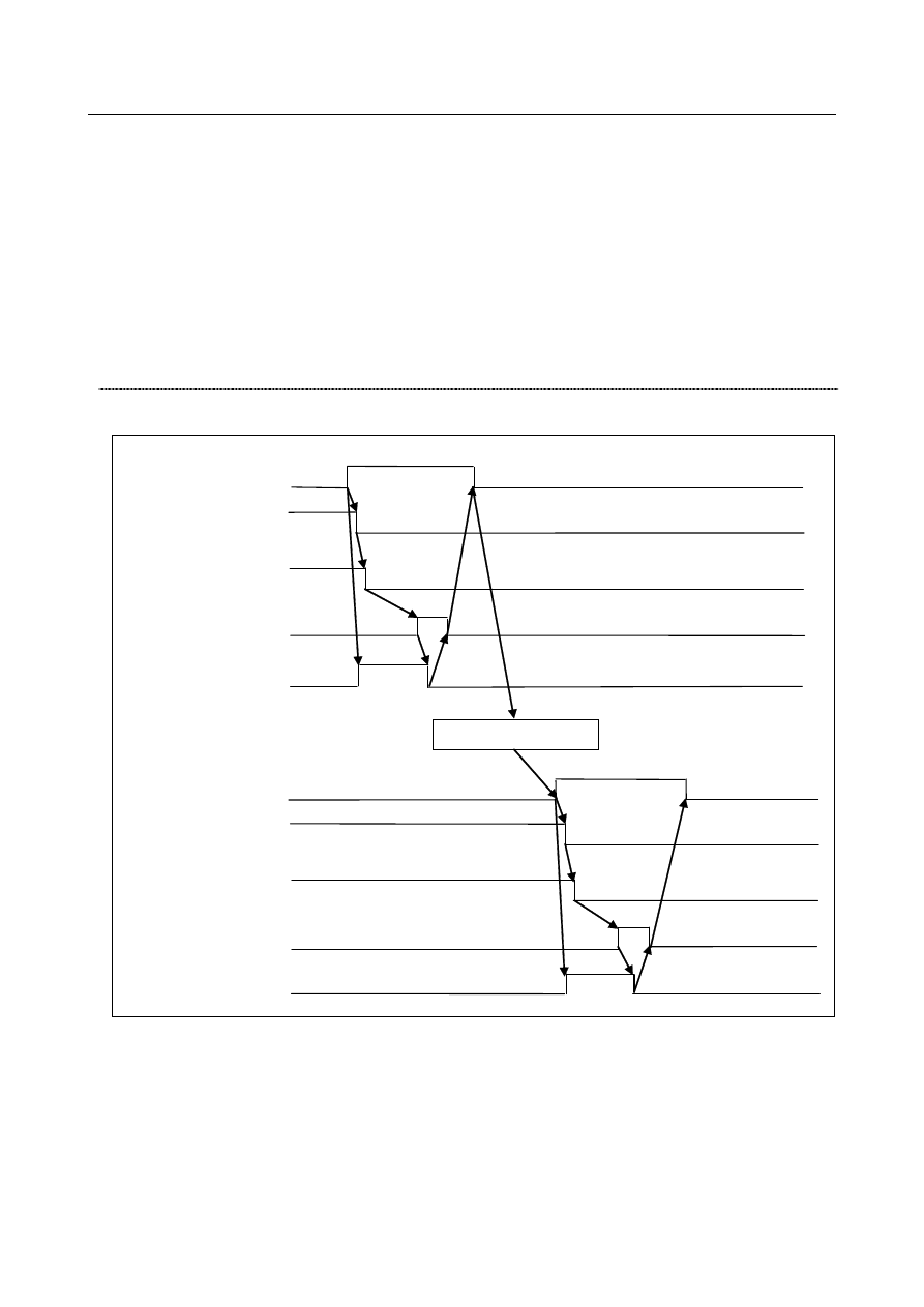
When  the  M code for enabling the inter-path flexible synchronization  mode  is specified and the 
inter-path flexible synchronization  mode select signal  OVLN is set to "1",  the inter-path flexible 
synchronization mode signal becomes "1". 

2. 

The end signal FIN is operated for completion. 

3. 

The waiting M code is specified in both the master and slave axis paths. 

4. 

When  the  M code for enabling  flexible  synchronization  control is specified, and the  flexible 
synchronization  control mode selection signal  MTA, MTB, MTC, or MTD is set to "1", 
synchronization starts. 
And the flexible  synchronization  control mode status signal MFSYNA, MFSYNB, MFSYNC,  or 
MFSYND becomes "1". 

5. 

When the flexible synchronization control mode signal becomes "1", the end signal FIN is operated 
for completion. 


Synchronization cancellation 
Command sequence 


Inter-path flexible 
synchronization mode off M 
command 

Inter-path flexible 
synchronization mode signal 
OVLNS 
 

End signal FIN 
 

Strobe signal MF 

Inter-path flexible 
synchronization mode select 
signal OVLN 

Synchronization cancel M 
command 

Flexible synchronization 
control mode signal 
MFSYNA 

End signal FIN 
 

Strobe signal MF 

Flexible synchronization 
control mode select signal 
MTA 

Waiting between paths 


Fig. 1.12.5 (c) 

 
1. 

When  the  M code for canceling  flexible  synchronization  control is specified, and the  flexible 
synchronization control mode selection signal is set to "0", synchronization is canceled. 

2. 

When the flexible synchronization  control mode status signal becomes "0", the end signal FIN is 
operated for completion. 

3. 

The waiting M code is specified in both the master and slave axis paths. 

4. 

When  the  M code for disabling the inter-path flexible synchronization  mode  is specified,  and  the 
inter-path flexible synchronization  mode select signal  OVLN is set to "0",  the inter-path flexible 
synchronization mode is canceled. 

B-64693EN-1/01


1. AXIS CONTROL


- 403 - 

5. 

When the inter-path flexible synchronization mode signal becomes 0, the end signal FIN is operated 
for completion. 


Notes 

NOTE 

1  If an overtravel alarm occurs on the slave axis, the tool is stopped along both the 

master and slave axes, and alarm PS5245, "OTHER AXIS ARE COMMANDED" 
is issued in the master axis path. 

2  If a servo alarm occurs, flexible synchronization control is canceled, and alarm 

PS5245 is issued in both the master and slave paths. 

3  If an emergency stop is applied, flexible synchronization control is canceled and 

alarm PS5245 is issued in the path in which the emergency stop is not applied. 
When bit 1 (FCN) of parameter No. 1342 is 1, however, synchronization is not 
canceled and no alarm is issued. 

4  Machine lock, if applied to the slave axis, is disabled while flexible 

synchronization is enabled. 


Parameter 

5660 


Master axis number for flexible synchronization control (group A) 


5661 


Slave axis number for flexible synchronization control (group A) 


5662 


Master axis number for flexible synchronization control (group B) 


5663 


Slave axis number for flexible synchronization control (group B) 


5664 


Master axis number for flexible synchronization control (group C) 


5665 


Slave axis number for flexible synchronization control (group C) 


5666 


Master axis number for flexible synchronization control (group D) 


5667 


Slave axis number for flexible synchronization control (group D) 


[Input type]  Parameter input


 [Data Input type]  Word path 
[Valid data range]  0 to Number of controlled axes   

or m 

×

 100+n (m:1 to Number of paths, n:1 to Number of controlled axes) 

Specify both master and slave axis numbers. 
Setting value) 

1 to 24: Controlled axes on own path (one path system only) 
101 to 124: Controlled axes in path 1 
201 to 224: Controlled axes in path 2 

 
In inter-path flexible synchronization  control, an axis of a path can be specified as the 
master axis of another path. 
 

NOTE 


In inter-path flexible synchronization control, an axis of any path 
cannot be specified as the slave axis of another path. 


1. AXIS CONTROL


B-64693EN-1/01


- 404 - 


#7 

#6 

#5 

#4 

#3 

#2 

#1 

#0 

13421 


FSV 

FRF 

FCN 


  [Input type]  Parameter input 


  [Data type]  Bit path


NOTE 


Set these parameters for the first path only. It will be effective to all 
paths. 


#1  FCN

  In the emergency stop/servo off state, inter-path flexible synchronization control is: 

0: 

Canceled. 

1: 

Not canceled. 


#2  FRF

  If G27/G28/G29/G30/G53 is specified during flexible synchronization  control, alarm 

PS0010 is: 
0: 

Issued. 

1: 

Is not issued. Commands to the master axis are possible. 

Even if, however, parameter bit 2 (FRF) is set to 1, and G28 is specified for the master 
axis in the state in which the reference position of the master axis subject to flexible 
synchronization  control is not established, or if G27/G28/G29/G30/G53 is specified for 
the slave axis, alarm PS5381 is issued. 
 

NOTE 


When Inter-path flexible synchronization control is valid, even if 0 is 
set in the parameter bit FRF, the operation will be the same as that 
if 1 is set. 


#3  FSV

  When the axis related to synchronization is servo off state while flexible synchronization 

control or inter-path flexible synchronization control, an automatic operation is: 
0: 

Stopped. 

1: 

Stopped if the axis related to synchronization moves. 


NOTE 


In inter-path flexible synchronization control, this parameter 
becomes effective when parameter FCN (No.13421#1) is set to 1. 


Signal 

Inter-path flexible synchronization mode select signal OVLN<Gn531.4> 

  [Classification]  Input signal 
 

[Function]  Inter-path flexible synchronization  control is enabled during automatic operation when 

the inter-path flexible synchronization mode is enabled in the relevant paths. 


[Operation]  When this signal becomes "1", the control unit operates as follows: 

Enables the inter-path flexible synchronization mode in the relevant paths. 


NOTE 

1  To switch the inter-path flexible synchronization mode select signal 

between "1" and "0", the tool must be stopped along all axes (other 
than PMC axes) in the target path. If the tool moves along any axis, 
alarm DS0071 "START OR RELEASE CANNOT BE DONE" is 
issued. 

B-64693EN-1/01


1. AXIS CONTROL


- 405 - 

NOTE 

2  Be sure to specify the waiting M code following the M code for 

enabling the inter-path flexible synchronization mode during 
automatic operation. 

3  Be sure to specify the waiting M code preceding the M code for 

disabling the inter-path flexible synchronization mode during 
automatic operation. 


Inter-path flexible synchronization mode signal OVLNS<Fn545.1> 

  [Classification]  Output signal 
 

[Function]  This signal indicates the inter-path flexible synchronization mode status. 


[Operation]  This signal becomes "1" when: 

The relevant path is in the inter-path flexible synchronization mode. 

This signal becomes "0" when: 

The relevant path is not in the inter-path flexible synchronization mode.


Signal address 


#7 

#6 

#5 

#4 

#3 

#2 

#1 

#0 

Gn531 


OVLN 


#7 

#6 

#5 

#4 

#3 

#2 

#1 

#0 

Fn545 


OVLNS 


Alarm and message 

Number 

Message 

Description 

PS0502 

ILLEGAL G-CODE 

A G code unavailable in the inter-path flexible synchronization 
mode was specified. 

PS5242 

ILLEGAL AXIS NUMBER 

This alarm is issued when either of the following conditions is 
satisfied. 
(It is issued at the start of inter-path flexible synchronization 
control.) 
1. The master or slave axis number is invalid. 
2. The relation among master and slave axes makes a loop. 

PS5244 

TOO MANY DI ON 

When an attempt was made to change the flexible 
synchronization control status, the select signal was not turned 
on or off after the execution of the M code. 

An attempt was made to turn flexible synchronization control 
on or off without stopping the tool along all axes. 
(Except when automatic phase synchronization for flexible 
synchronization control is used) 

Flexible synchronization control was turned off in any of the 
following function modes: 

Tilted working plane indexing 

PS5245 

OTHER AXIS ARE 
COMMANDED 

This alarm is issued when one of the following conditions is 
satisfied: 
1.  An overtravel alarm occurred in the slave axis. 
2.  A servo alarm occurred in a path in inter-path flexible 

synchronization control. 

3.  An emergency stop was applied in another path in inter-path 

flexible synchronization control. 

4.  When an attempt was made to execute flexible synchronization 

between different paths during automatic operation, the 
inter-path flexible synchronization mode was not enabled. 

1. AXIS CONTROL


B-64693EN-1/01


- 406 - 

Number 

Message 

Description 

PS5381 

INVALID COMMAND IN FSC 
MODE 

Either of the following commands was specified: 

G28 was specified for the master axis when the reference 
position was not established for the master axis of flexible 
synchronization control. 

G27, G28, G29, G30, or G53 was specified for the slave axis. 

DS0071 

START OR RELEASE CANNOT 
BE DONE 

To start or cancel the inter-path flexible synchronization mode, the 
tool must be stopped along all axes. 


1.12.6 

Skip Function for Flexible Synchronization Control 

Outline 

This function enables the skip or high-speed skip signal (in the following explanation, these signals are 
collectively called skip signal) for the slave axis that is moved by command of the master axis in the 
flexible synchronization control mode. 
This function has features such as the following: 

If a skip signal is input while a skip command for flexible synchronization  control  block is being 
executed, this block does not terminate until the specified number of skip signals have been input. 

The machine coordinates assumed when skip signals are input and the number of input skip signals 
are stored in specified custom macro variables. 

The total number of the skip signal inputs is stored in another specified custom macro variable. 


Format 

Mxx ;                           Flexible synchronization control mode on 

G31.8 G91 

α

0 P_ Q_ R_ ;            Skip command for flexible synchronization 

control 

α


:  Specify the slave axis. The instruction value must be 0. It is considered 0 even if 

numbers except 0 are specified. 

P_  :  The top number of the consecutive custom macro variables in which the machine 

coordinate positions of the slave axis at the skip signal inputs are stored. 

Q_  :  The maximum allowable number of the skip signal inputs. (Range of command 

value: 1 to 512)   

R_  :  The number of the custom macro variables in which the total number of the inputs 

is stored. 


This data is usually the same as the value specified by Q.   


Therefore this is not necessarily specified. Specify it to check the number of skip 
signal inputs. 

 
G31.8 is a one-shot G code. 
During the execution of the G31.8 block, the machine coordinate positions of the slave axis at the skip 
signal inputs are stored in the consecutive custom macro variables where the top number of the variables 
is specified by P and the maximum allowable number of the skip signal inputs is specified by Q. 
Also, this total number of the skip signal inputs is stored in the variable specified by R. 
 
Example) 

Mxx 


Flexible synchronization control mode on 

X-- 
Y-- 
G31.8 G91 A0 P100 Q30 R1 

Skip command for flexible synchronization control 

 
After 30 times of skip signal inputs, 30 machine coordinate positions of the A axis are stored respectively 
in the consecutive custom macro variables #100 to #129. 
The total number of skip signal inputs is stored in the custom macro variable #1. 

B-64693EN-1/01


1. AXIS CONTROL


- 407 - 


NOTE 

1  In the G31.9 or G31.8 block, when the axis was not specified, the alarm 

(PS1152) "G31.9/G31.8 FORMAT ERROR" occurs. 

2  In the G31.8 block, only one slave axis should be commanded. When more than 

two slave axes are specified, the alarm (PS1152) occurs. 

3  If G31.8 is commanded out of the flexible synchronization control mode (Flexible 

synchronization control mode status signal switching accepted signal (MFSYNA, 
MFSYNB, MFSYNC or MFSYND) is “0”), the alarm (PS1152) occurs. 

4  If P is not specified, the alarm (PS1152) occurs. 
5  If the axis besides a slave axis is specified, the alarm (PS1152) occurs. 
6  If Q is specified out of range, the alarm (PS1152) occurs. 
7  If P is not specified, the alarm (PS1152) occurs. 
8  If R is not specified, the number of input skip signals is not written to a custom 

macro variable. 

9  The number of custom macro variables specified in P and R must be the existing 

ones. If any nonexistent variable is specified, the alarm (PS0115) "VARIABLE 
NO. OUT OF RANGE" occurs. If a variable shortage occurs, the alarm (PS0115) 
occurs, too. 

10 Whether to use conventional skip signals or high-speed skip signals with this 

function can be specified with the bit 4(HSS) of parameter No.6200. When 
high-speed skip is selected, specify which high-speed signals to enable with 
setting parameter 9S1 to 9S8 (No.6208#0 to #7). 

11 The accumulated pulses and positional deviation due to 

acceleration/deceleration is considered and compensated when storing the 
machine coordinate positions to the custom macro variables.   


Signal 


Please refer about signals of skip and flexible synchronization control to the following specification. 


”Skip function”  and  “Flexible  synchronization  control”  of  “FANUC Series 0

i

-F Plus 

CONNECTION MANUAL (FUNCTION) (B- 64693EN-1)”. 


Parameter 


#7 

#6 

#5 

#4 

#3 

#2 

#1 

#0 

6200 


SRE 

SLS 

HSS 


SK0 

GSK 


[Input type]  Parameter input 


[Data type]  Bit path 


#0  GSK

  As a skip signal, the skip signal SKIPP is 

0: 

Invalid. 

1: 

Valid. 


#1  SK0

  This parameter specifies whether the skip signal is made valid under the state of the skip 

signal SKIP and the multistage skip signals SKIP2 to SKIP8. 
0: 

Skip signal is valid when these signals are "1". 

1: 

Skip signal is valid when these signals are "0". 


#4  HSS

  0: 

The skip function does not use high-speed skip signals while skip signals are input. 


(The conventional skip signal is used.) 

1: 

The step skip function uses high-speed skip signals while skip signals are input. 


1. AXIS CONTROL


B-64693EN-1/01


- 408 - 


#5  SLS

  0: 

The multi-step skip function does not use high-speed skip signals while skip signals 
are input. 


(The conventional skip signal is used.)


1: 

The multi-step skip function uses high-speed skip signals while skip signals are 
input. 


NOTE 


The skip signals (SKIP and SKIP2 to SKIP8) are valid regardless of 
the setting of this parameter. They can also be disabled using bit 4 
(IGX) of parameter No. 6201. 


If you want to use high-speed skip signals when the multi-step skip 
function is used, set this parameter to 1. 


#6  SRE

  When a high-speed skip signal is used: 

0: 

The signal is assumed to be input on the rising edge (contact open 

  close). 

1: 

The signal is assumed to be input on the falling edge (contact close 

  open). 


#7 

#6 

#5 

#4 

#3 

#2 

#1 

#0 

6201 


SKPXE 


CSE 

IGX 


[Input type]  Parameter input 


[Data type]  Bit path 


#4  IGX

  When the high-speed skip function is used, SKIP, SKIPP, and SKIP2 to SKIP8 are: 

0: 

Enabled as skip signals. 

1: 

Disabled as skip signals. 


#5  CSE

  For the continuous high-speed skip command, high-speed skip signals are: 

0: 

Effective at either a rising or falling edge (depending on the setting of bit 6 (SRE) of 
parameter No.6200) 

1: 

Effective at both the rising and falling edges.


#7  SKPXE

  For the skip function (G31), the skip signal SKIP is: 

0: 

Enabled. 

1: 

Disabled. 


Whether the skip signals are enabled or disabled 

Parameter 

Bit 4 (IGX) of 

parameter 

No. 6201 

Bit 0 (GSK) 

of parameter 

No. 6200 

Bit 7 (SKPXE) 

of parameter 

No .6201 

Skip 

signal 

SKIPP 

Skip 

signal 

SKIP 

Multistage skip 

signals 

SKIP2-SKIP8 

Setting 

Disabled 

Enabled 

Enabled 

Enabled 

Enabled 

Enabled 

Disabled 

Disabled 

Enabled 

Enabled 

Disabled 

Enabled 

Disabled 

Disabled 

Disabled 

Disabled 

Disabled 

Disabled 

Disabled 

Disabled 

Disabled 

Disabled 

Disabled 

Disabled 

 
Bit 4 (IGX) of parameter No. 6201 is valid for the skip function using high-speed skip 
signals (when bit 4 (HSS) of parameter No. 6200 is set to 1) or for the  multi-step  skip 
function using high-speed skip signals (when bit 5 (SLS) of parameter No. 6200 is set to 
1). 

B-64693EN-1/01


1. AXIS CONTROL


- 409 - 


#7 

#6 

#5 

#4 

#3 

#2 

#1 

#0 

6208 


9S8 

9S7 

9S6 

9S5 

9S4 

9S3 

9S2 

9S1 


[Input type]  Parameter input 


[Data type]  Bit path 


9S1 to 9S8

  Specify which high-speed skip signal is enabled for the continuous high-speed skip 

command G31P90 or the EGB skip and the skip function for  flexible  synchronization 
control command G31.8.


The settings of each bit have the following meaning: 
0: 

The high-speed skip signal corresponding to the bit is disabled. 

1:    The high-speed skip signal corresponding to the bit is enabled. 
The bits correspond to signals as follows: 

Parameter 

High-speed skip signal 

Parameter 

High-speed skip signal 

9S1 

HDI0 

9S5 

HDI4 

9S2 

HDI1 

9S6 

HDI5 

9S3 

HDI2 

9S7 

HDI6 

9S4 

HDI3 

9S8 

HDI7 


6220 

  Period during which skip signal input is ignored for the continuous high-speed skip function , EGB axis 

skip function , and flexible synchronization control skip function 


[Input type]  Parameter input 


[Data type]  Byte path 


[Unit of data]  8msec 

[Valid data range]  3 to 127(

×

 8msec) 

This parameter specifies the period from when a high-speed skip signal is input to when 
the next high-speed skip signal can be input for the continuous high-speed skip function, 
EGB axis skip function, and flexible synchronization control skip function. 
This parameter is used to ignore chattering in skip signals. 
If a value that falls outside the valid range is specified, the setting is assumed to be 24 
msec. 
 
Example 1) When bit 5 (CSE) of parameter No. 6201 is 0 and bit 6 (SRE) of parameter 
No. 6200 is 0: 


Signal ignoring period (parameter No. 6220) 

High-speed skip 
signals 

This signal is ignored. 


Example 2) When bit 5 (CSE) of parameter No. 6201 is 1: 


Signal ignoring period (parameter No. 6220) 

High-speed skip 
signals 

These signals 
are ignored. 


Content      ..     54      55      56      57     ..