FANUC Series 0i-MODEL F Plus. CONNECTION MANUAL (FUNCTION) - page 55
 

  Index      Manuals     FANUC Series 0i-MODEL F Plus. CONNECTION MANUAL (FUNCTION) B-64693EN-1/01


Search            copyright infringement  


Content      ..     53      54      55      56     ..


FANUC Series 0i-MODEL F Plus. CONNECTION MANUAL (FUNCTION) - page 55


1. AXIS CONTROL


B-64693EN-1/01


- 394 - 

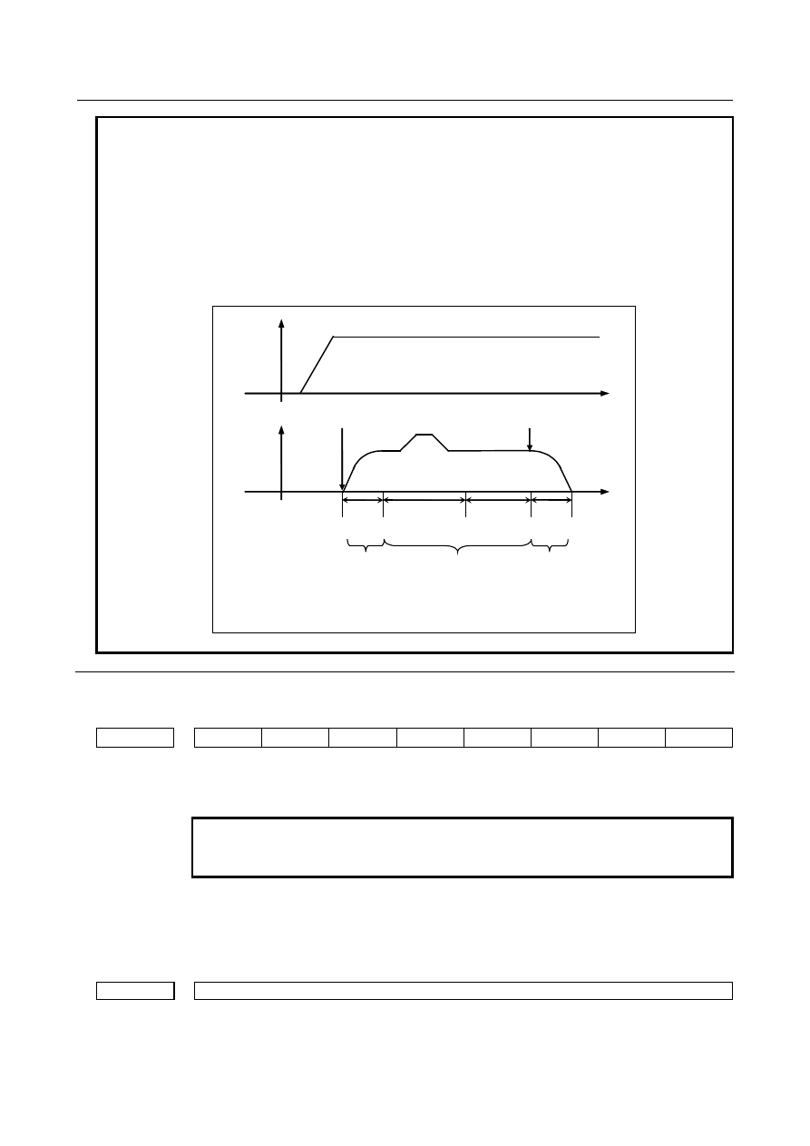
NOTE 

1  To use this function, the axes related to the synchronization must be rotary axes 

A type.   

2  If 0 or less is set to parameter No.7778, this function is disabled. 
3  If 0 or less is set to parameter No.5697, constant acceleration (specified by 

parameter No.7778) is applied in all speed area.   

4  This function is valid in acceleration/deceleration of synchronization 

start/cancellation. This function is invalid in acceleration/deceleration of 
automatic phase synchronization. 


Synchronization 
cancellation command 

Synchronization   
start command 

Speed of 
slave axis 

Acceleration 

Deceleration 

Automatic phase 
synchronization 

Speed of 
master axis 

This function   
is disable 

This function   
is enabled 

This function   
is enabled 

synchroniza- 
tion state 


Parameter 


#7 

#6 

#5 

#4 

#3 

#2 

#1 

#0 

5694 


PAV 


[Input type]  Parameter input 


[Data type]  Bit path 


NOTE 


When this parameter is set, the power must be turned off before 
operation is continued. 


#2  PAV

  Variable acceleration function  in automatic phase synchronization for flexible 

synchronization control is: 
0: 

Disabled.   

1: 

Enabled. 


5697 


Acceleration switch speed of slave axis in synchronization start/cancellation 


[Input type]  Parameter input 


[Data type]  2-word axis 


[Unit of data]  min

-1


B-64693EN-1/01


1. AXIS CONTROL


- 395 - 

[Valid data range]  0 to 99999999 

This parameter set the acceleration  switch speed of slave axis in synchronization 
start/cancellation. If 0 or less is set to this parameter, constant acceleration (specified by 
parameter No.7778) is applied in all speed area. 
 

NOTE 


This parameter is valid If 1 is set to the parameter 
PAV(No.5694#2).   


7778 


Acceleration of slave axis in synchronization start/cancellation 


[Input type]  Parameter input 


[Data type]  Real axis 


[Unit of data]  mm/sec

2

, inch/ sec

2

, deg/sec

2


[Minimum unit of data]  Depend on the increment system of the applied axis 
[Valid data range]  Refer to the standard parameter setting table (D) 

(For a millimeter machine, 0.0 to +100000.0, for an inch machine, 0.0 to +10000.0) 
When variable acceleration function in automatic phase synchronization for flexible 
synchronization control is valid (PAV(No.5694#2)=1), this parameter sets acceleration of 
slave axis in synchronization start/cancellation.  If 0 or less is set to this  parameter, 
variable acceleration function in automatic phase synchronization for flexible 
synchronization control is disabled. 


1.12.4 

Synchronization Positional Difference Detection Diagnosis 
Display and Signal Output in Flexible Synchronization 
Control 

Overview 

This function displays the diagnosis data and outputs DO signal <Fn533> for confirming error of between 
master axis and slave axis after executing automatic  phase  synchronization  for  flexible synchronization 
control. 
 

Diagnosis data 

Error (parameters  Nos.  5600 to 5603) and maximum error (parameters  Nos.  5604 to 5607) between 
master axis and slave axis after executing automatic phase synchronization are displayed. 
 

Output signal 

If a positional error  detected after automatic phase synchronization exceeds any of the settings of 
parameters Nos. 13437 to 13440 (threshold values for phase synchronization positional error detection 
signal output), the DO signal <Fn553> is output. 
 

Signal 

Automatic phase synchronization error detection signals PHERA, PHERB, PHERC, 

PHERD <Fn553.0-Fn553.3> 

  [Classification]  Output signal 
 

[Function]  This signal can be used to check whether an automatic phase synchronization positional 

difference has exceeded the setting of parameters Nos. 13437 to 13440 (threshold values 
for automatic phase synchronization positional error detection signal output). 
This signal becomes "1" when: 

Error of automatic phase synchronization excess threshold values. 

This signal becomes "0" when: 

Error of automatic phase synchronization does not excess threshold values. 

1. AXIS CONTROL


B-64693EN-1/01


- 396 - 

Flexible synchronization control phase synchronization end  signal  PHFINA, 
PHFINB, PHFINC, PHFIND <Fn381.0-Fn381.3> is "0". 


Signal address 


#7 

#6 

#5 

#4 

#3 

#2 

#1 

#0 

Fn553 


PHERD 

PHERC 

PHERB 

PHERA 


Parameter 

13437 


Threshold value for automatic phase synchronization error detection signal output (group A) 


13438 


Threshold value for automatic phase synchronization error detection signal output (group B) 


13439 


Threshold value for automatic phase synchronization error detection signal output (group C) 


13440 


Threshold value for automatic phase synchronization error detection signal output (group D) 


[Input type]  Parameter input 


[Data type]  Real path 


[Unit of data]  mm, inch, deg (machine unit) 

[Min. unit of data]  Depend on the increment system of the reference axis 
[Valid data range]  0 or positive 9 digit of minimum unit of data (refer to the standard parameter setting table 

(B)) 
(When the increment system is IS-B, 0.000 to +999999.999) 
If error between master axis and slave axis after  executing  automatic  phase 
synchronization  for  flexible synchronization control, automatic  phase  synchronization 
error detection signal PHERA, PHERB, PHERC, PHERD is turned "1". 
Please set this parameter in the path of slave axis in inter-path flexible  synchronization 
control. 
 

Diagnosis data 

5600 


Error of automatic phase synchronization (group A) 


5601 


Error of automatic phase synchronization (group B) 


5602 


Error of automatic phase synchronization (group C) 


5603 


Error of automatic phase synchronization (group D) 


[Data type]  Real path 


[Unit of data]  mm, inch, deg (machine unit) 

[Min. unit of data]  Depend on the increment system of the reference axis 
[Valid data range]  9 digit of minimum unit of data 

(When the increment system is IS-B, -999999.999 to +999999.999) 
Error between master axis and slave axis after executing automatic phase Synchronization 
for flexible synchronization control is displayed. 
This data is displayed in the path of slave axis in inter-path flexible  synchronization 
control. 


5604 


Maximum error of Automatic Phase Synchronization (group A) 


5605 


Maximum error of Automatic Phase Synchronization (group B) 


5606 


Maximum error of Automatic Phase Synchronization (group C) 


5607 


Maximum error of Automatic Phase Synchronization (group D) 


B-64693EN-1/01


1. AXIS CONTROL


- 397 - 


[Data type]  Real path 


[Unit of data]  mm, inch, deg (machine unit) 

[Min. unit of data]  Depend on the increment system of the reference axis 
[Valid data range]  9 digit of minimum unit of data 

(When the increment system is IS-B, -999999.999 to +999999.999) 
Maximum error between master axis and slave axis after executing automatic phase 
synchronization for flexible synchronization control is displayed. 
This data is displayed in the path of slave axis in inter-path flexible  synchronization 
control. 
This data is cleared when automatic operation is started in auto mode. 
This data is cleared when flexible synchronization control is started in manual mode. 


Notes 

NOTE 


Diagnosis data is displayed after the following time passes since flexible 
synchronization control phase synchronization end signal is turned "1". 


1/ (Parameter No.1825 

 0.01) 

 3 [sec] 


Example) 
 

If No. 1825 = 3000, diagnosis data is displayed 100 msec later. 


This function is usable only when the gear ratio between the master and slave 
axes is 1 vs. 1. 


1.12.5 

Inter-path Flexible Synchronization Control 

Overview 

Inter-path flexible synchronization  control enables 

flexible 

synchronization

  control between axes in 

different paths in a multi-path system.


Up to four slave axes can be specified in one path. 
An axis in another path can be specified as the master axis of each slave axis. 
Synchronization for all synchronization pairs in all paths can be executed simultaneously. 
 
Example) 
 

In a multi-path system with the following axis configuration (Fig. 1.12.5 (a)), not only 
synchronization between the C1 axis in path 1 (master axis) and the A1 axis in path 1 (slave axis), 
but also synchronization between the C1 axis in path 1 (master axis) and the A2 axis in path 2 (slave 
axis) can be performed. 

1. AXIS CONTROL


B-64693EN-1/01


- 398 - 


Path 1 

C1 axis 

(workpiece axis) 

A1 axis (tool 

axis) 

C2 axis   

A2 axis (tool 

axis) 

Path 2 

Synchronization 

Synchronization 

Master 

Slave 

Slave 


Fig. 1.12.5 (a) 


Details 

Setting of synchronization axes 

Set master axis numbers in parameters Nos. 5660, 5662, 5664, and 5666. 
Set slave axis numbers in parameters Nos. 5661, 5663, 5665, and 5667. 
Set the number obtained by adding the controlled axis number to path number 

×

 100 in these parameters 

for the slave axis path. 
 
Example) 
 

Master axis: 1st axis in path 1, slave axis: 1st axis in path 2 


Parameter No. 5660 (path 2) = 101 


Parameter No. 5661 (path 2) = 201 

 
A slave axis in a synchronization group can be set as the master axis in another group. 
Example) 
 

The following synchronization is be applied: 


X1 

X2 

X1 (master) 

 X2 (slave) 


X2 (master) 

 Y2 (slave) 


Y (master) 

 Y1 (slave) 


Y1 

Y2 

 
If the relation among the master and slave axes makes a loop, however, alarm PS5242 "ILLEGAL AXIS 
NUMBER" is issued when synchronization starts. 

B-64693EN-1/01


1. AXIS CONTROL


- 399 - 

Example) 
 

The following synchronization cannot be applied: 


X1 

X2 

X1 (master) 

 X2 (slave) 


X2 (master) 

 Y2 (slave) 


Y2 (master) 

 X1 (slave) 


Y1 

Y2 


X1 is defined as its own master axis. 


Specification method 

To execute inter-path flexible synchronization control during  automatic operation, it is necessary  to put 
the CNC in the inter-path flexible synchronization mode by setting the inter-path flexible synchronization 
mode select signal OVLN <Gn531.4> to "1" with a ladder program by specifying an M code in the paths 
to which the master and slave axes belong. 

 
If flexible synchronization is started when the inter-path flexible synchronization  mode is off, alarm 
PS5245 "OTHER AXIS ARE COMMANDED" is issued. 
The inter-path flexible synchronization mode is disabled by setting OVLN to "0". 

 
For the program sequence of the inter-path flexible synchronization mode status and M code commands 
for flexible synchronization control, see the following example. 
 
Example) 

Path of master axis 

Path of slave axis 

M210; ------ Turns the inter-path flexible synchronization 

mode on. 

M100P12; ------ Waiting (Note 1) 

M310; ------ Turns the inter-path flexible synchronization 

mode on.   

M100P12; ------ Waiting (Note 1) 

 
  : ------ Master axis move commands 

M60; ------ Starts inter-path flexible synchronization. 
~


M61; ------ Cancels inter-path flexible synchronization. 


M110P12; ------ Waiting (Note 1) 
M211; ------ Turns the inter-path flexible synchronization 

mode off.   


M110P12; ----- Waiting (Note 1) 
M311; ------ Turns the inter-path flexible synchronization 

mode off.   

 
AI contour control I/II can be turned on or off when both the master and slave paths are in the inter-path 
flexible synchronization mode. 
AI contour control I/II can also be turned on or off even if PMC axis control is used for the master axis 
during flexible synchronization. 
 

NOTE 

1  Specify the waiting M code after the M code for turning the inter-path flexible 

synchronization mode on and before the M code for turning the inter-path flexible 
synchronization mode off during automatic operation. 

2  The M code for turning the inter-path flexible synchronization mode on controls 

signals as follows: 


Sets the inter-path flexible synchronization mode select signal OVLN to "1" and 
confirms that the inter-path flexible synchronization mode signal OVLNS 
<Fn545.1> is changed to "1". 

3  The M code for turning the inter-path flexible synchronization mode off controls 

signals as follows: 


Sets the inter-path flexible synchronization mode select signal OVLN to "0" and 
confirms that the inter-path flexible synchronization mode signal OVLNS is 
changed to "0". 

1. AXIS CONTROL


B-64693EN-1/01


- 400 - 


Restrictions 

The following functions cannot be specified in the inter-path flexible synchronization mode. 
If any of these functions is specified in the inter-path flexible synchronization  mode, alarm PS0502 
"ILLEGAL G-CODE" is issued. 

Reference return in Cs contouring control (G00, G28)


Skip function (G31)


Automatic tool length measurement/Automatic tool offset function


Automatic reference return operation of low-speed type (G28)


High-speed program check function


These functions can be specified when flexible synchronization  control and the inter-path flexible 
synchronization mode are turned off. 
 

Inter-path flexible synchronization mode turned on immediately after power-on 

When the inter-path flexible synchronization mode select signal is set to "1" immediately after power-on, 
the waiting M code does need to be specified. 
For the program sequence of the inter-path flexible synchronization mode status and M code commands 
for flexible synchronization control, see the following example. (This example also explains the sequence 
when G31 is specified.) 
 
Example) 

Path of master axis 

Path of slave axis 

Set OVLN to 1. 
(The inter-path flexible synchronization mode is turned 
on.) 

Set OVLN to 1. 
(The inter-path flexible synchronization mode is turned 
on.) 

 
  : ------ Master axis move commands 

M60; ------ Starts inter-path flexible synchronization. 

M61; ------ Cancels inter-path flexible synchronization. 

M110P12; ------ Waiting 
M211; ------ Turns the inter-path flexible synchronization 

mode off. (NOTE 1)   

M110P12; ----- Waiting 
M311; ------ Turns the inter-path flexible synchronization 

mode off. (NOTE 1)   

G31_ ; 

M210; ------ Turns the inter-path flexible synchronization 

mode on. (NOTE 1)   

M100P12; ------ Waiting 

M310; ------ Turns the inter-path flexible synchronization 

mode on. (NOTE 1)   

M100P12; ------ Waiting 

 
  : ------ Master axis move commands 

M60; ------ Starts inter-path flexible synchronization. 

M61; ------ Cancels inter-path flexible synchronization. 


NOTE 

1  Turn the inter-path flexible synchronization mode on or off after flexible 

synchronization is canceled in the slave path. 

2  Start or cancel flexible synchronization control with the signal (MTA, MTB, MTC, 

or MTD) in the slave path. Specify the M code for starting or canceling flexible 
synchronization in a block without specifying other commands. 

B-64693EN-1/01


1. AXIS CONTROL


- 401 - 

NOTE 

3  Flexible synchronization control cannot be started or canceled in the slave axis 

path while the path is in any of the following modes. In any of these modes, 
alarm PS5244, “TOO MANY DI ON” is issued. 
-  Tilted working plane indexing 


Flexible synchronization control can be started or canceled in the master axis 
path, however. 

4  Use an M code preventing buffering as the M code for turning the inter-path 

flexible synchronization mode on or off. (Parameter No. 3411 to 3420 or 11290 
to 11299) 


Specify the M code for turning the inter-path flexible synchronization mode on or 
off in a block without specifying other commands. 

5  Do not specify any move or PMC axis control command between the M code for 

turning the inter-path flexible synchronization mode on or off and a waiting M 
code. 

6  An axis in spindle control with servo motor cannot be used as the master axis of 

flexible synchronization control. 


Synchronization start 
Command sequence 


Flexible synchronization 
control mode select signal 
MTA 

Flexible synchronization 
control mode signal 
MFSYNA 
 

End signal FIN 


Strobe signal MF 
 

Synchronization start M 
command 

Waiting between paths 

Inter-path flexible 
synchronization mode select 
signal OVLN 

End signal FIN 
 

Strobe signal MF


Inter-path flexible 
synchronization mode on M 
command 

Inter-path flexible 
synchronization mode signal 
OVLNS 


Fig. 1.12.5 (b) 


Content      ..     53      54      55      56     ..