FANUC Series 0i-MODEL F Plus. CONNECTION MANUAL (FUNCTION) - page 54
 

  Index      Manuals     FANUC Series 0i-MODEL F Plus. CONNECTION MANUAL (FUNCTION) B-64693EN-1/01


Search            copyright infringement  


Content      ..     52      53      54      55     ..


FANUC Series 0i-MODEL F Plus. CONNECTION MANUAL (FUNCTION) - page 54


1. AXIS CONTROL


B-64693EN-1/01


- 386 - 

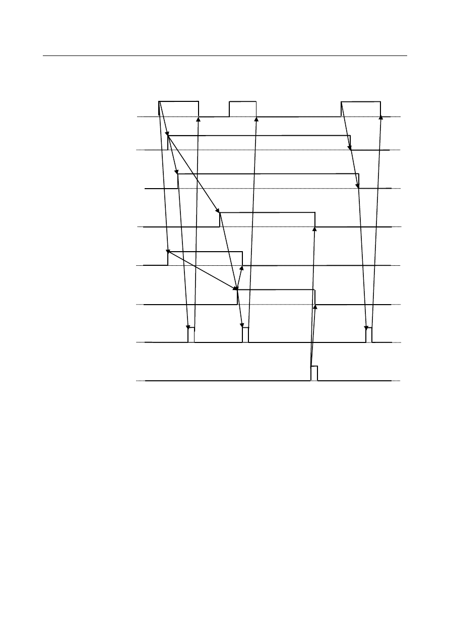
Example of time chart high speed type for acceleration / deceleration and 

automatic phase synchronization 


Strobe signal 
MF<Fn007.0> 

Flexible synchronization 
control mode selecting   
signal 
FSYSA<Fn553.4> 

Flexible synchronization 
control mode status signal 
MFSYNA<Fn197.0> 

Flexible synchronization 
control automatic phase 
synchronization signal 
AUTPHA<Gn381.0> 


Flexible synchronization 
control phase 
synchronization end signal 
PHFINA<Fn381.0> 

End signal 
FIN<Gn004.3> 

Flexible synchronization 
control mode selection   
signal 
MTA<Gn197.0> 

Command of M code 
for beginning deceleration 
of a slave axis 

B-64693EN-1/01


1. AXIS CONTROL


- 387 - 

Example of time chart high speed type for acceleration / deceleration and 

automatic phase synchronization (Hob command) 


Signal 

Flexible synchronization control mode selection signals 
 

MTA, MTB, MTC, MTD <Gn197.0 to Gn197.3> 

  [Classification]  Input signal 
 

[Function]  These signals select flexible synchronization control. 


[Operation]  1) 

Synchronization starts when these signals become "1". 

2) 

Synchronization is canceled when these signals become "0". 

 
MTA: Selects synchronization for group A. 
MTB: Selects synchronization for group B. 
MTC: Selects synchronization for group C. 
MTD: Selects synchronization for group D. 
 

Flexible synchronization control mode status signals 
 

MFSYNA, MFSYNB, MFSYNC, MFSYND <Fn197.0 to Fn197.3> 

  [Classification]  Output signal 

Strobe signal 
MF<Fn007.0> 

Flexible synchronization 
control mode selecting   
signal 
FSYSA<Fn553.4> 

Flexible synchronization 
control mode status signal 
MFSYNA<Fn197.0> 

Flexible synchronization 
control automatic phase 
synchronization signal 
AUTPHA<Gn381.0> 

Flexible synchronization 
control phase 
synchronization end signal 
PHFINA<Fn381.0> 

End signal 
FIN<Gn004.3> 

Synchronous beginning / 
cancel 
G code command 

Command of M code 
for beginning deceleration 
of a slave axis 

1. AXIS CONTROL


B-64693EN-1/01


- 388 - 


[Function]  These signals check whether the group selected by a flexible synchronization  control 

mode selection signal has actually entered the mode. 


[Operation]  These signals become "1" when: 

Acceleration/deceleration is applied at the start of synchronization and the 
synchronization feedrate is reached. 

These signals become "0" when: 

Deceleration starts at synchronization cancellation. 

The gear ratio is changed during automatic operation. 

 
MFSYNA: Synchronization select switching for group A has been accepted. 
MFSYNB: Synchronization select switching for group B has been accepted. 
MFSYNC: Synchronization select switching for group C has been accepted. 
MFSYND: Synchronization select switching for group D has been accepted. 
 

Flexible synchronization control automatic phase synchronization signals 
 

AUTPHA, AUTPHB, AUTPHC, AUTPHD <Gn381.0 to Gn381.3> 

  [Classification]  Input signal 
 

[Function]  These signals select automatic phase synchronization for flexible synchronization control. 


[Operation]  When these signals are "0", automatic phase synchronization is not executed. 

When these signals are "1", automatic phase synchronization is executed after 
acceleration/deceleration applied at the start of synchronization start is completed. 
(When the flexible synchronization  control mode status signal is "1", automatic phase 
synchronization is executed.) 
When these signals are set to 0, then "1" again during synchronization, automatic phase 
synchronization is executed again. 
 
AUTPHA: Selects automatic phase synchronization for group A. 
AUTPHB: Selects automatic phase synchronization for group B. 
AUTPHC: Selects automatic phase synchronization for group C. 
AUTPHD: Selects automatic phase synchronization for group D. 
 

Flexible synchronization control phase synchronization end signals 
 

PHFINA, PHFINB, PHFINC, PHFIND <Fn381.0 to Fn381.3> 

  [Classification]  Output signal 
 

[Function]  These signals notify that automatic phase synchronization for flexible synchronization 

control is completed. 


[Operation]  These signals become "1" when: 

Automatic phase synchronization is completed. 

These signals become "0" when: 

The flexible synchronization control mode status signal becomes "0". 

 
PHFINA: Notifies that automatic phase synchronization for group A is completed. 
PHFINB: Notifies that automatic phase synchronization for group B is completed. 
PHFINC: Notifies that automatic phase synchronization for group C is completed. 
PHFIND: Notifies that automatic phase synchronization for group D is completed. 
 

Flexible synchronization control mode selecting signals 
 

FSYSA, FSYSB, FSYSC, FSYSD <Fn553.4 to Fn553.7> 

  [Classification]  Output signal 
 

[Function]  These signals notify that the change to flexible synchronization control mode is begun. 


[Operation]  These signals become "1" when: 

The change to flexible synchronization control mode is begun. 

These signals become "0" when: 

Flexible synchronization control mode is canceled 

B-64693EN-1/01


1. AXIS CONTROL


- 389 - 


NOTE 

If the bit 1 (PHS) of parameter No.5694 is set to 1, this signal is 
enabled. 


Signal address 


#7 

#6 

#5 

#4 

#3 

#2 

#1 

#0 

Gn197 


MTD 

MTC 

MTB 

MTA 


#7 

#6 

#5 

#4 

#3 

#2 

#1 

#0 

Gn381 


AUTPHD 

AUTPHC 

AUTPHB 

AUTPHA 


#7 

#6 

#5 

#4 

#3 

#2 

#1 

#0 

Fn197 


MFSYND 

MFSYNC 

MFSYNB 

MFSYNA 


#7 

#6 

#5 

#4 

#3 

#2 

#1 

#0 

Fn381 


PHFIND 

PHFINC 

PHFINB 

PHFINA 


#7 

#6 

#5 

#4 

#3 

#2 

#1 

#0 

Fn553 


FSYSD 

FSYSC 

FSYSB 

FSYSA 


Parameter 


#7 

#6 

#5 

#4 

#3 

#2 

#1 

#0 

5669 


PHD 

PHC 

PHB 

PHA 


[Input type]  Parameter input 

  [Data Input type]  Bit path


#0  PHA

  The automatic phase synchronization for flexible synchronization control of group A is: 

0: 

Disabled. 

1: 

Enabled. 


#1  PHB

  The automatic phase synchronization for flexible synchronization control of group B is: 

0: 

Disabled. 

1: 

Enabled. 


#2  PHC

  The automatic phase synchronization for flexible synchronization control of group C is: 

0: 

Disabled. 

1: 

Enabled. 


#3  PHD

  The automatic phase synchronization for flexible synchronization control of group D is: 

0: 

Disabled. 

1: 

Enabled. 


NOTE 


When this parameter is set, acceleration/deceleration upon a 
synchronization start or synchronization cancellation is enabled. 
For automatic positioning, set the automatic phase synchronization 
signal for each group to "1". 


#7 

#6 

#5 

#4 

#3 

#2 

#1 

#0 

5694 


PHS 


  [Input type]  Parameter input 


  [Data type]  Bit path


1. AXIS CONTROL


B-64693EN-1/01


- 390 - 

NOTE 


When this parameter is set, the power must be turned off before 
operation is continued. 


#1  PHS

  Speed-up of automatic phase synchronization for flexible synchronization control is: 

0: 

Disabled. 

1: 

Enabled. 


5696 


M code for beginning deceleration for canceling synchronization 


  [Input type]  Parameter input 


  [Data type]  2 Word path


[Valid data range]  0 to 99999999 

This parameter set M code for beginning deceleration for canceling synchronization. 
The M code of group A : Number set to this parameter 
The M code of group B : Number set to this parameter + 1 
The M code of group C : Number set to this parameter + 2 
The M code of group D : Number set to this parameter + 3 
When this parameter is set to 0, the M code is disabled. 
 

NOTE 

1  If the bit 1 (PHS) of parameter No.5694 is set to 1, this parameter 

is enabled. 

2  Do not set an M code used with other functions (such as M00-05, 

30, 98, and 99, and M codes for calling subprograms). 


#7 

#6 

#5 

#4 

#3 

#2 

#1 

#0 

13420 


DID 

DIC 

DIB 

DIA 


  [Input type]  Parameter input 


  [Data type]  Bit path


#0  DIA

  The movement direction of the automatic phase synchronization of group A is: 

0: 

+ direction. 

1: 

- direction. 


#1  DIB

  The movement direction of the automatic phase synchronization of group B is: 

0: 

+ direction. 

1: 

- direction. 


#2  DIC

  The movement direction of the automatic phase synchronization of group C is: 

0: 

+ direction. 

1: 

- direction. 


#3  DID

  The movement direction of the automatic phase synchronization of group D is: 

0: 

+ direction. 

1: 

- direction. 


13425 


Acceleration/deceleration time constant of the slave axis when synchronization is started/canceled 

(group A) 


13426 


Acceleration/deceleration time constant of the slave axis when synchronization is started/canceled 

(group B) 


B-64693EN-1/01


1. AXIS CONTROL


- 391 - 

13427 


Acceleration/deceleration time constant of the slave axis when synchronization is started/canceled 

(group C) 


13428 


Acceleration/deceleration time constant of the slave axis when synchronization is started/canceled 

(group D) 


  [Input type]  Parameter input 


  [Data type]  Word path


[Unit of data]  msec 

[Valid data range]  0 to 4000 

These parameters set the acceleration/deceleration time constants of the slave axis subject 
to automatic phase synchronization for flexible synchronization control. 
The acceleration when synchronization is started/canceled will be as follows: 
Acceleration = parameter No.1420 / parameters Nos.13425 to 13428 
 

13429 


Automatic phase synchronization feedrate for the slave axis (group A) 


13430 


Automatic phase synchronization feedrate for the slave axis (group B) 


13431 


Automatic phase synchronization feedrate for the slave axis (group C) 


13432 


Automatic phase synchronization feedrate for the slave axis (group D) 


[Input type]  Parameter input 


[Data type]  Real path 


[Unit of data]  mm/min, inch/min, deg/min (machine unit) 

[Min. unit of data]  Depend on the increment system of the applied axis 
[Valid data range]  Refer to the standard parameter setting table (C) 

(When the increment system is IS-B, 0.0 to +999000.0) 
These parameters set the automatic phase synchronization  feedrates for the slave axis 
subject to automatic phase synchronization. 
These feedrates are superimposed on the feedrate synchronized to the master axis. 
If the setting of one of the parameters is 0, the automatic phase synchronization feedrate 
for the corresponding group will be 6 (mm/min). 
 

13433 


Machine coordinates of the master axis used as the reference for phase synchronization (group A) 


13434 


Machine coordinates of the master axis used as the reference for phase synchronization (group B) 


13435 


Machine coordinates of the master axis used as the reference for phase synchronization (group C) 


13436 


Machine coordinates of the master axis used as the reference for phase synchronization (group D) 


[Input type]  Parameter input 


[Data type]  Real path 


[Unit of data]  mm, inch, deg (machine unit) 

[Min. unit of data]  Depend on the increment system of the applied axis 
[Valid data range]  9 digit of minimum unit of data (refer to standard parameter setting table (A)) 

(When the increment system is IS-B, -999999.999 to +999999.999) 
These parameters set the machine coordinates of the master axis used as the reference for 
phase synchronization. If the setting of this parameter is 0, the origin position 
(coordinates: 0) of the machine coordinate system of the master axis will be the reference 
position for automatic phase synchronization. 
 

1. AXIS CONTROL


B-64693EN-1/01


- 392 - 

Alarm and message 

Number 

Message 

Description 

PS5242 

ILLEGAL AXIS NUMBER 

A master axis number or a slave axis number was not 
set correctly when the flexible synchronization control 
mode was turned from off to on during automatic 
operation. 

Automatic phase synchronization is effective, and a set 
increment system of the master axis and the slave axis 
is different. 

Automatic phase synchronization is effective, and the 
setting of the rotation axis of the master axis or the 
slave axis is illegal. 

PS5381 

INVALID COMMAND IN FSC MODE 

The gear ratio is changed without canceling 
synchronization after specifying M code of beginning 
deceleration for canceling synchronization. 


Notes 

NOTE 

1  The next block is not executed until acceleration/deceleration at the start or 

cancellation of synchronization is completed during automatic operation. 

2  Due to an error produced when the output pulses for the slave axis are 

calculated, the phase of the slave axis may not be matched by least input 
increment. This error is not accumulated. 

3  If a retract operation is performed during automatic phase synchronization, the 

automatic phase synchronization is stopped and the retract operation is 
performed. After the completion of the retract operation, restarting the program 
resumes the automatic phase synchronization. However, no request for 
automatic phase synchronization is accepted during a retract operation. 

4  It is necessary to set increment system of the master axis and the slave axis to 

the same setting. If flexible synchronization is started when it is different setting, 
alarm PS5242 "OTHER AXIS ARE COMMANDED" is issued. 

5  When the master axis and the slave axis are the following settings, automatic 

phase match cannot be used. If flexible synchronization is started, alarm PS5242 
"OTHER AXIS ARE COMMANDED" is issued. 
-  Either the master axis or the slave axis is rotation axis, and the type of 

rotation axis is A type. 

-  Both the master axes and the slave axes are the rotation axes, and the type 

of the rotation axis is different. 

-  Both the master axes and the slave axes are the rotation axes of type A, and 

the value of parameter No.1260 is different. 


1.12.3 

Variable Acceleration Function in Automatic Phase 
Synchronization for Flexible Synchronization Control 

Outline 

In automatic phase synchronization for flexible synchronization control, acceleration of slave axis can be 
changed depending on the speed in during synchronization start/cancellation. 
 

Explanation 

Over the base speed, output characteristic of a spindle motor is constant and its torque characteristic 
decreases in inverse proportion to the speed.  Therefore if the target speed is over the base speed in the 

B-64693EN-1/01


1. AXIS CONTROL


- 393 - 

linear acceleration pattern, low  acceleration must be set depending on torque characteristic at the target 
speed, and motor torque can not be used efficiently in the low speed area.  If this variable acceleration 
function is used, the acceleration is constant (specified by parameter No.7778) in lower speed area than 
parameter No.5697 and the acceleration decreases in inverse proportion to the speed in higher speed area 
than parameter No.5697. To use this function, set the parameter PAV(No.5694#2) to 1. 


Fig. 1.12.3 (a)    Acceleration of slave in synchronization start/cancellation 


Speed of slave axis   

Speed of slave axis used for acceleration calculation of this function is the number of rotation calculated 
by the shift amount per one rotation of a rotary axis specified by the parameter No.1260. Set the value to 
parameter No.5697 considering this calculation. 
 

Acceleration in higher speed area than parameter No.5697 

The acceleration decreases in inverse proportion to the speed. The acceleration is as follows: 
 

speed

Current 

No.5697


Parameter 

No.7778


Parameter 


on

Accelerati

×

=


No.7778 

Acceleration of slave axis 

Speed of slave aixs 

No.5697 


Content      ..     52      53      54      55     ..