FANUC Series 0i-MODEL F Plus. CONNECTION MANUAL (FUNCTION) - page 47
 

  Index      Manuals     FANUC Series 0i-MODEL F Plus. CONNECTION MANUAL (FUNCTION) B-64693EN-1/01


Search            copyright infringement  


Content      ..     45      46      47      48     ..


FANUC Series 0i-MODEL F Plus. CONNECTION MANUAL (FUNCTION) - page 47


1. AXIS CONTROL


B-64693EN-1/01


- 330 - 

C-axis CMR:  1 
C-axis FFG n/m:  1/100 
 
In this case, the number of pulses per spindle rotation is: 
  80000 

×

 1/1 = 80000 

Therefore, set 80000 for parameter No. 7772. 
The number of pulses per C-axis rotation in the detection unit is: 


360000


=


100

1

36

1

1000000

×

÷


Therefore, set 360000 for parameter No. 7773. 


[Example 2]  When the gear ratio of the spindle to the detector B is 2/3 for the above example (When 

the detector rotates twice for three spindle rotations) 
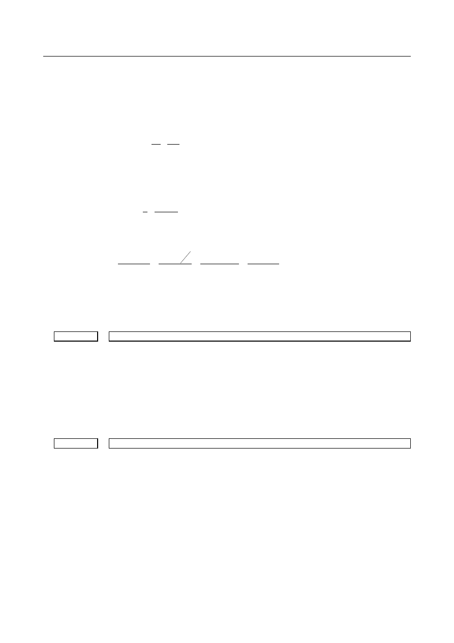
In this case, the number of pulses per spindle rotation is: 


3

160000


=


3

2

80000

×


160000 cannot be divided by 3 without a remainder. In this case, change the setting of 
parameter No. 7773 so that the ratio of the settings of parameters Nos. 7772 and 7773 
indicates the value you want to set. 


1080000

160000


=


3

360000

160000


=


360000

3

160000


=


No.7773

No.7772

×


Therefore, set 160000 for parameter No. 7772 and 1080000 for parameter No. 7773. 
As described above, all the settings of parameters Nos. 7772 and 7773 have to do is to 
indicate the ratio correctly. So, you can reduce the fraction indicated by the settings. For 
example, you may set 16 for parameter No. 7772 and 108 for parameter No. 7773 for this 
case. 
 

7782 


Number of pulses from the position detector per EGB master axis rotation 


[Input type]  Parameter input 


[Data type]  2-word axis 


[Unit of data]  Detection unit 

[Valid data range]  1 to 999999999 

For a slave axis, set the number of pulses generated from the position detector per EGB 
master axis rotation. 
For an A/B phase detector, set this parameter with four pulses equaling one A/B phase 
cycle. 
 

7783 


Number of pulses from the position detector per EGB slave axis rotation 


[Input type]  Parameter input 


[Data type]  2-word axis 


[Unit of data]  Detection unit 

[Valid data range]  1 to 999999999 

For a slave axis, set the number of pulses generated from the position detector per EGB 
slave axis rotation. 
Set the number of pulses output by the detection unit. 
Set this parameter when using the G81.5 EGB synchronization command. 
The method for setting parameters Nos. 7782 and 7783 is the same as for parameters Nos. 
7772 and 7773. For the method, see the description of parameters Nos. 7772 and 7773. 
 

B-64693EN-1/01


1. AXIS CONTROL


- 331 - 

The ratio of the number of pulses for the master slave to that of pulses for the slave axis 
may be valid, but the settings of the parameters may not indicate the actual number of 
pulses. For example, the number of pulses may not be able to be divided without a 
remainder for the reason of the master and slave axis gear ratios as described in example 
2. In this case, the following methods cannot be used for the G81.5 command: 
 
G81.5 T_ C_ ; 

When the speed is specified for the master axis and the travel distance 
is specified for the slave axis 

G81.5 P_ C0 L_ ;  When the number of pulses is specified for the master axis and the 

speed is specified for the slave axis 


#7 

#6 

#5 

#4 

#3 

#2 

#1 

#0 

2005 


FEEDx 


[Input type]  Parameter input 


[Data type]  Bit axis 


#1  FEEDx

  Feed-forward function is: 

0: 

Invalid. 

1: 

Valid. 

 
Set 1 for the EGB slave axis. 

NOTE 


This parameter is Initial setting parameter. For details, refer to the 
appendix "Automatic setting / Initial setting parameter" in this 
manual. 


2068 


Feed-forward function coefficient 


[Input type]  Parameter input 


[Data type]  Word axis 

[Valid data range]  0 to 100 

Setting value = 

a


×

 100 

 
Set 10000 for the EGB slave axis. 


#7 

#6 

#5 

#4 

#3 

#2 

#1 

#0 

2273 


EGFx 


[Input type]  Parameter input 


[Data type]  Bit axis 


#6  EGFx

  FFG is: 

0: 

Not considered in the synchronization coefficient. 

1: 

Considered. 

 
The synchronization coefficient is subject to the following restriction: 

Synchronization coefficient 

α

β

×

T

L


where 

word

1

word

2

T

L

×

α

β

  : Condition <1> 

where 
L  :  Number of hob threads 
T  :  Number of teeth


1. AXIS CONTROL


B-64693EN-1/01


- 332 - 

a

  :  Number of pulses of the position detector per rotation about the master axis 

(parameter No. 7772 or 7782) 

β

  :  Number of pulses of the position detector per rotation about  the slave axis 

(parameter No. 7773 or 7783) 

If this condition, <1>, cannot be satisfied, set this parameter bit to 1. With this setting, 
FFG is considered in the synchronization coefficient, and by selecting FFG appropriately, 
it is possible to set 

a

  and 

β

  in such a way that condition <1> can be satisfied with the 

synchronization coefficient kept intact. 


Synchronization coefficient 

M

N

T

L

×

×

α

β


where 

word

word

T

L

1

2

×

α

β

  : Condition <1> 

N: Numerator of FFG 
M: Denominator of FFG 


The new value of 

a

 is the old one multiplied by FFG. 

M

N


]

Old

[


]


New


[


×

α

α


Setting example 


Slave axis control 

Number of pulses of the 
position detector per rotation 
about the slave axis 
parameter No. 7773 or 7783 

Number of pulses of the 
position detector per rotation 
about the master axis 
parameter No. 7772 or 7782 

Slave axis 

1,000,000 p/rev 

Master axis 

1-to-1 connection 

Separate detector 
(phase A/B) 
12,000 p/rev 

EGB ratio 

FFG 

FFG 


Fig. 1.9.5.4 (c) 

 
Master axis conditions: 
 

The separate detector must be 12000 p/rev. 


The master axis and the separate detector must have a 1-to-1 connection. 

Slave axis conditions: 
 

The motor Pulsecoder must be 1 million p/rev. 


FFG must be 1/100. 

 
Determine FFG so that condition <1> is satisfied. 

word

1

word

2

T

L

×

α

β

  : Condition <1> 

In this example, FFG is set to 1/10. Set bit 6 (EGF) of parameter No. 2273, which is a 
function bit to consider FFG in EGB, to 1, and set the number of pulses of the position 
detector per rotation about the master and slave axes. 

B-64693EN-1/01


1. AXIS CONTROL


- 333 - 

 
As the number of pulses of the position detector per rotation about the master axis, set 
12000 x FFG (1/10) = 1200. 
As the number of pulses of the position detector per rotation about the slave axis, set 
10000. 


#7 

#6 

#5 

#4 

#3 

#2 

#1 

#0 

4399 


SOSALWs 


[Input type]  Parameter input 


[Data type]  Bit spindle 


  #2  SOSALWs

  The Soft start/stop function is: 

0: 

Disabled at an emergency stop (*ESP is ”0”) or MRDY is ”0”. 

1: 

Enabled even at an emergency stop (*ESP is ”0”) or MRDY is ”0”. 


4030 


Soft start/stop setting time 


[Input type]  Parameter input 


[Data type]  Word spindle 


[Unit of data]  1min

-1

/sec 

[Valid data range]  0 to 32767 

This parameter sets an acceleration (rate at which the speed changes) applied when the 
Soft start/stop function is enabled (the Soft start/stop signal SOCNA <Gn071> is ”1”). 
 

4508 


Acceleration rate change applied at Soft start/stop 


[Input type]  Parameter input 


[Data type]  Word spindle 


[Unit of data]  10min

-1

/sec

2


[Valid data range]  0 to 32767 

This parameter sets an acceleration rate (rate at which the acceleration changes) applied 
when the Soft start/stop function is enabled (the Soft start/stop signal SOCNA <Gn071> 
is ”1”). 
 

NOTE 


If the setting of this parameter is 0, it means that the speed to be 
applied when the Soft start/stop function is enabled is linear. 


Alarm and message 

Number 

Message 

Description 

PS1593 

EGB PARAMETER SETTING 
ERROR 

Error in setting a parameter related to the EGB 
(1)  The setting of bit 0 (SYNx) of parameter No. 2011, is not 

correct. 

(2)  The slave axis specified with G81 is not set as a rotation axis. 

(bit 0 (ROTx) of parameter No. 1006) 

(3)  Number of pulses per rotation 

(Parameter (No. 7772 or 7773) or (No. 7782 or 7783) ) is not 
set. 

(4)  Parameter No. 7710 is not set for a command compatible with 

that for a hobbing machine. 

1. AXIS CONTROL


B-64693EN-1/01


- 334 - 

Number 

Message 

Description 

PS1594 

EGB FORMAT ERROR 

Error in the format of the block of an EGB command 
(1)  T (number of teeth) is not specified in the G81 block. 
(2)  In the G81 block, the data specified for one of T, L, P, and Q is 

out of its valid range. 

(3)  In the G81 block, only one of P and Q is specified. 
(4)  In the G81.5 block, no command is specified for the master or 

slave axis. 

(5)  In the G81.5 block, data outside the valid data range is 

specified for the master or slave axis. 

PS1595 

ILL-COMMAND IN EGB MODE 

During synchronization with the EGB, a command that must not be 
issued is issued. 
(1)  Slave axis command using G27, G28, G29, G30, G33, G53, 

etc. 

(2)  Inch/metric conversion command using G20, G21, etc. 
(3)  Synchronization start command using G81 or G81.5 when bit 

3 (ECN) of parameter No. 7731 is 0 

PS1596 

EGB OVERFLOW 

An overflow occurred in the calculation of the synchronization 
coefficient. 


Reference item 

Manual name 

Item name 

OPERATOR’S MANUAL (B-64694EN) 

Electronic gear box 2 pair 


1.9.6 

U-axis Control 

Overview 

To control an axis on a spindle such as the U-axis of a vertical lathe from a motor mounted on other than 
the spindle, a mechanism was conventionally required which used a planetary gear box, differential gears, 
and others to prevent the movement along the U-axis as the spindle rotated. 
The U-axis control function enables the tool to remain in a fixed position on the U-axis or to move at a 
programmed feedrate without using a mechanism such as a planetary gear box. This is done by causing 
the U-axis motor to rotate in such a way that the movement along the U-axis, which should be caused by 
rotation of the spindle, is canceled out. 
 
An electronic gear box (EGB) is used to cause the U-axis motor to rotate in synchronization with the 
spindle. 
With the EGB, the servo CPU processes signals received from the position coder mounted on the spindle 
at high speed to control the movement along the U-axis. It is capable of high-precision synchronous 
control. The EGB requires axis control circuits for two axes (U-axis and U’-axis). It acquires the pulses 
necessary for synchronization from the separate feedback connector on the U’-axis side. With the EGB, 
the spindle, which is used as the reference for synchronization, is called the master axis. The U-axis, 
along which the tool moves in synchronization with the master axis, is called the slave axis. The U’-axis, 
which acquires the pulses necessary for synchronization, is called the dummy axis. 

B-64693EN-1/01


1. AXIS CONTROL


- 335 - 


Synchronization coefficient 

Detector 

Spindle 

Motor 

Spindle amplifier 

Spindle control 

Detector 

Motor 

Servo amplifier 

Velocity/current control 

Positional control 


Synchronization switch 

U-axis 

CNC 

Separate Detector 


Fig. 1.9.6 (a) Block diagram of U-axis control 


Example 


U-axis


Spindle


Fig. 1.9.6 (b) Example of a machine having the U-axis 


1. AXIS CONTROL


B-64693EN-1/01


- 336 - 


-axis 

Spindle motor 

-axis motor 

Spindle 


Fig. 1.9.6 (c) Example of the structure of a machine having the U-axis 

 
In the example of the above structure, the tool moves along the U-axis when the spindle rotates. This 
movement is canceled out by rotating the U-axis motor. 
 

Explanation 

  - 

Synchronization start 

Synchronization is started when the EGB synchronization mode selection signal EGBS<Gn067.4> is set 
to  “1”. In the synchronization mode, the EGB synchronization mode confirmation signal 
EGBSM<Fn082.6> becomes “1”. 
If the U-axis motor rotates in synchronization with the spindle in the synchronization mode, the machine 
coordinates are not updated, that is, the machine coordinates indicate the position on the U-axis based on 
the spindle. 
 

  - 

Synchronization cancellation 

Synchronization is canceled when the EGB synchronization mode selection signal EGBS<Gn067.4>  is 
set to “0”. When synchronization is canceled, the EGB synchronization mode confirmation signal 
EGBSM<Fn082.6> also becomes “0”. 


  - 

Parameter Setting 

(1)  Set the following parameters: 

U-axis control enable: Bit 1 (UAX) of parameter No. 7702 

Number of pulses per rotation about the spindle: Parameter No. 7772 

Amount of travel by the U-axis motor per rotation about the spindle: Parameter No. 7773 

EGB function enable: Bit 0 (SYNx) of parameter No. 2011 

Parameters for feed forward control 

(2)    Be sure to set bit 0 (SYNx) of parameter No. 2011 to 1 for both the U-axis and dummy axis. 
(3)  Set the servo parameters for the dummy axis (parameters  Nos. 2000 to 2999) such that they are 

consistent with the settings made for the U-axis. 

(4)  Be sure to set the command multiplier (CMR) for the dummy axis to the same value as for the 

U-axis. 

(5)  The following parameters need not be set for the dummy axis: 

Reference counter size: Parameter No. 1821 

In-position width: Parameter No. 1826 

Positioning deviation limit in movement/in the stopped state: Parameters Nos. 1828 and 1829 

Stored stroke limits: Parameter No. 1320 and others 

B-64693EN-1/01


1. AXIS CONTROL


- 337 - 

(6)  Set the values related to the flexible feed gear ratio for the dummy axis (parameters Nos. 2084 and 

2085) to 1. 

(7)  The dummy axis occupies one servo axis interface. Set servo axis numbers consecutively for the 

dummy axis and U-axis so that an odd number and an even number are assigned. 


Example 1) 
 

When the dummy axis is the 4th out of total four axes: 


1st axis  Parameter No. 1023: 1 


2nd axis  Parameter No. 1023: 2 


3rd axis  Parameter No. 1023: 3 (U-axis) 


4th axis  Parameter No. 1023: 4 (dummy axis) 

Example 2) 
 

When the dummy axis is the 5th out of total five axes: 


1st axis  Parameter No. 1023: 1 


2nd axis  Parameter No. 1023: 2 


3rd axis  Parameter No. 1023: 5 


4th axis  Parameter No. 1023: 3 (U-axis) 


5th axis  Parameter No. 1023: 4 (dummy axis) 

(8)  Set bit 0 (HBR) of parameter No. 7700 to 1 so as not to cancel synchronization by the reset 

operation. 

(9)


Set bit 1 (UFF) of parameter No. 7786 to 1, when a interpolation command to between the U-axis and 
the other axes is specified while U-axis synchronization. 

(10)  Parameter setting related to feed forward control 

Step 1. 
 

Modify the motor type for the U-axis and dummy axis and set them automatically. 

Parameter No. 2020 = Motor number 

Bit 1 (DGPx) of parameter No. 2000 = 0 

Set the above parameters, then turn the power off, then on again. 

 
Step 2. 
 

Set the parameters related to the EGB again. 

Bit 0 (SYNx) of parameter No. 2011 = 1 (for both the U-axis and dummy axis) 


Bit  1  (FFAL) of parameter No.  2011  = 1, when feed forward control is also enabled in 
rapid traverse. 

 
Step 3. 
 

Other parameters (set them for the U-axis only.) 

Bit 3 of parameter No. 2003 = 1 (P-I control) 

Bit 1 of parameter No. 2005 = 1 (feed forward enable) 

Parameter No. 2068 = 10000 (feed forward coefficient) 

Parameter No. 2092 = 10000 (look-ahead feed forward coefficient) 

 
Step 4. 
 

Suppressing load variation 


Increase the value of parameter No. 2021 (within the range in which the motor does not 
oscillate). 


Set this parameter to the value obtained from the following: 


256 

×

 (machine load inertia) / (motor rotor inertia) 

 
For details of parameter setting, refer to the subsection titled “Feed-forward Function”  in  “CONTOUR 
ERROR SUPPRESSION FUNCTION”  in  “FANUC AC SERVO MOTOR 

a

i

/

β

i

  series,  FANUC 

LINEAR MOTOR L

i

S series, FANUC SYNCHRONOUS BUILT-IN SERVO MOTOR D

i

S series 

PARAMETER MANUAL (B-65270EN)”. 


Content      ..     45      46      47      48     ..