FANUC Series 0i-MODEL F Plus. CONNECTION MANUAL (FUNCTION) - page 48
 

  Index      Manuals     FANUC Series 0i-MODEL F Plus. CONNECTION MANUAL (FUNCTION) B-64693EN-1/01


Search            copyright infringement  


Content      ..     46      47      48      49     ..


FANUC Series 0i-MODEL F Plus. CONNECTION MANUAL (FUNCTION) - page 48


1. AXIS CONTROL


B-64693EN-1/01


- 338 - 

(11)


Set  bit 0 (NDPx) of parameter No.3115 to 1 for the U axis control dummy axis to disable current 

position display. 

(12)


When the U-axis control mode is released, when the tool is moved along the U-axis to the position 

where the reference counter is 0, set bit 3 (UOC) is parameter No.7704 to 1. 


-  Notes related to alarms 

(1)  Servo alarm, spindle alarm, and emergency stop 

All axis motors are de-energized, U-axis synchronization is canceled, and the EGB synchronization 
mode confirmation signal EGBSM<Fn082.6>  becomes  “0”. If the spindle is rotating, the 
cancellation of synchronization may cause the tool to abruptly move along the U-axis. 

(2)  U-axis servo off 

The U-axis motor is de-energized, but U-axis synchronization is not canceled. If the spindle is 
rotating, the tool may abruptly move along the U-axis since the U-axis motor is de-energized. If the 
tool moves long the U-axis when the U-axis is in the servo off state, the pulses corresponding to the 
amount of travel is stored in the servo error counter regardless of the follow-up setting by bit 0 
(FUP) of parameter No. 1819 and the signal *FLWU <Gn007.5>. Therefore, when the servo off 
signal becomes “0”, the tool moves the along the U-axis so that the stored pulses become 0. When 
the EGB synchronization mode selection signal EGBS<Gn067.4> is set to “0”, the error amount also 
becomes 0. 

(3)  Other alarms 

The tool stops moving along each axis with the synchronization maintained. 


-  Notes for safety measures 

(1)  Synchronization is not maintained when the U-axis is in any of the following states: 

Emergency stop (both the CNC and serial spindle) 

Servo alarm 

Spindle alarm 

Servo-off 

Control axis detach 

Power failure 


If the spindle is rotating due to inertia in any of these states, the tool may abruptly move along the 
U-axis. In such cases, therefore, it is necessary to install some safety measures on the machine, such 
as applying a brake to the spindle or disengaging the clutch of the U-axis drive mechanism. 

(2)  Design the machine such that, when the U-axis motor comes to a halt, the tool always moves along 

the U-axis away from the workpiece, that is, to the safer side. 

(3)  When synchronization is off, it is dangerous, because the tool moves along the U-axis when the 

spindle rotates. The PMC must be equipped with some safety measures, such as monitoring the EGB 
synchronization mode confirmation signal EGBSM<Fn082.6>  and preventing the spindle from 
rotating if the confirmation signal is “0”. 

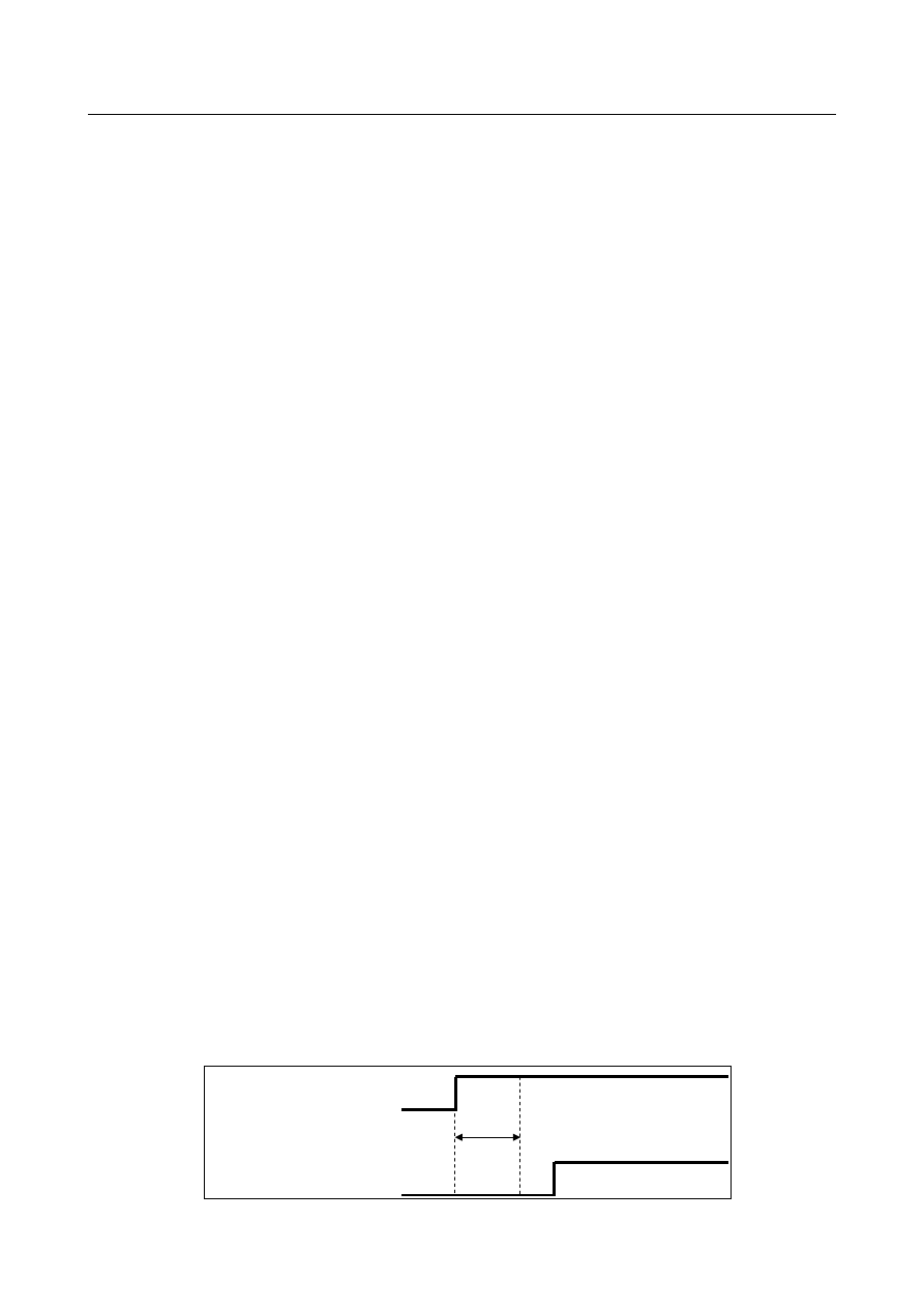
(4)  When you use U-axis control by Electronic Gear Box(FSSB type), set “1” to EGB synchronization 

mode selection signal EGBS<Gn067.4> according to following procedure (a) to (c). 


(a) Turn on CNC and confirm  the ready of all spindle  (All-spindle operation ready signal 
 

SRSRDY<Fn034.7>=”1”). 


(b) Wait about 40msec after (a). 


(c) Set the signal EGBS<Gn067.4> to “1”. 


If EGBS<Gn067.4> has been “1” since turning on CNC, a shock might occur at the point where the 
spindle passes the first one rotation signal. 

 All-spindle operation ready signal 
SRSRDY<Fn034.7> 

EGB synchronization mode selection 
signal EGBS<Gn067.4> 

40msec 


Fig. 1.9.6 (d) EGBS ON 

B-64693EN-1/01


1. AXIS CONTROL


- 339 - 

  Notes 

(1)  A synchronization coefficient is internally represented using a fraction (K2/K1) to eliminate an error. 

The formula below is used for calculation. 


Synchronization coefficient = 

K1

K2

  = 

α

β


where 


a

: Number of position detector pulses per rotation about the spindle (parameter No. 7772)


β

: Amount of travel by the U-axis motor per rotation about the spindle (parameter No. 7773) 


In the formula above, K2/K1 is obtained by reducing 

β

/

a

  to lowest terms, but K1 and K2 must 

satisfy the following restriction: 


-2147483648 

 K2 

 2147483647 


 K1 

 2147483647 

When this restriction is not satisfied, alarm PS1596,“EGB OVERFLOW”  is issued when 
synchronization starts. 

(2)  During synchronization, G00, G53, and canned cycles for drilling can be specified. 
(3)  Synchronization is maintained even if the U-axis or CNC unit is in any of the following states: 

Interlock 

Feed hold 

OT alarm 

PS alarm 

(4)  Synchronization pulses do not cause the machine, absolute, or relative coordinate of the U-axis to be 

updated. And the absolute coordinate of the U-axis is not updated when synchronization is canceled. 

(5)  EGB  synchronization  requires axis control circuits for two axes (U-axis and dummy axis). It 

acquires the pulses  necessary for synchronization  from the separate feedback connector on the 
dummy axis side. 

(6)  Any absolute position detector cannot be used for the U-axis. 
(7)  Controlled axes detach  cannot be applied to the U-axis. If controlled axes detach  is used for the 

U-axis, the synchronization mode is canceled. 

(8)  To turn synchronization on or off during automatic operation, use an M code preventing buffering to 

control the EGB synchronization mode selection signal EGBS<Gn067.4>. 

(9)  Dual check safety cannot be applied to the U-axis. 

Set bit 6 (DCNx) of parameter No. 1904 to 1 to disable dual check safety of the U-axis. 

(10)


Perform reference position return with synchronization off, when reference position return is not 
performed after power on. 


Signal 

EGB synchronization mode selection signal 
EGBS<Gn067.4> 

  [Classification]  Input signal 
 

[Function]  Selects the EGB synchronization mode for U-axis control. 


[Operation]  When this signal becomes “1”, the control unit operates as follows: 

Starts EGB synchronization. 


All-spindle operation ready signal 
SRSRDY <Fn034.7> 

  [Classification]  Output signal 
 

[Function]  This signal posts that all spindles used are ready for operation. 


[Operation]  This signal becomes “1” when: 


All used spindles become ready for operation. 

It becomes “0” when: 
 

Some of the used spindles are not ready for operation. 


1. AXIS CONTROL


B-64693EN-1/01


- 340 - 

EGB synchronization mode confirmation signal 
EGBSM<Fn082.6> 

  [Classification]  Output signal 
 

[Function]  Notifies the EGB synchronization for the U-axis control in active. 


[Operation]  This signal becomes “1” when: 


EGB synchronization in U-axis control is active. 

It becomes “0” when: 
 

EGB synchronization in U-axis control is canceled. 


Signal address 


#7 

#6 

#5 

#4 

#3 

#2 

#1 

#0 

Gn067 


EGBS 


Fn034 


SRSRDY 


Fn082 


EGBSM 


Parameter 

1023 


Number of the servo axis for each axis 


NOTE 


When this parameter is set, the power must be turned off before 
operation is continued. 


[Input type]  Parameter input 


[Data type]  Byte axis 

[Valid data range]  0 to 80 

This parameter associates each control axis with a specific servo axis. 
Usually set to same number as the control axis number. 
Specify values 1+8n, 2+8n, 3+8n, 4+8n, 5+8n, and 6+8n (n = 0, 1, 2, …, 9) like 1, 2, 3, 4, 
5, …, 77, and 78. 
For electronic gear box (EGB) controlled axes, two axes need to be specified as one pair. 
So, make a setting as described below. 
For a slave axis, set an odd (1, 3, 5, 7, 9, ...) servo axis number. For a dummy axis to be 
paired, set a value obtained by adding 1 to the value set for the slave axis. 
 

1320 


Coordinate value I of stored stroke check 1 in the positive direction on each axis 


1321 


Coordinate value I of stored stroke check 1 in the negative direction on each axis 


[Input type]  Parameter input 


[Data type]  Real axis 


[Unit of data]  mm, inch, deg (machine unit) 

[Min. unit of data]  Depend on the increment system of the applied axis 
[Valid data range]  9 digit of minimum unit of data (refer to standard parameter setting table (A)) 

(When the increment system is IS-B, -999999.999 to +999999.999) 
Set the coordinate value of stored stroke check 1 on each axis in the + or - direction in the 
machine coordinate system. 
 

B-64693EN-1/01


1. AXIS CONTROL


- 341 - 

NOTE 

1  Specify diameter values for any axes for which diameter 

programming is specified. 

2  The area outside the area set by parameters Nos. 1320 and 1321 

is a prohibited area. 


#7 

#6 

#5 

#4 

#3 

#2 

#1 

#0 

1819 


FUPx 


[Input type]  Parameter input 


[Data type]  Bit axis 


#0  FUPx

  To perform follow-up when the servo is off is set for each axis. 

0: 

The follow-up signal, *FLWU<Gn007.5>, determines whether follow-up is 
performed or not. 
When *FLWU<Gn007.5> is “0”, follow-up is performed. 
When *FLWU<Gn007.5> is “1”, follow-up is not performed. 

1: 

Follow-up is not performed. 


NOTE 


When using the index table indexing function, set FUPx to 1 for a 
control axis subject to index table indexing. 


1821 


Reference counter size for each axis 


NOTE 


When this parameter is set, the power must be turned off before 
operation is continued. 


[Input type]  Parameter input 


[Data type]  2-word axis 


[Unit of data]  Detection unit 

[Valid data range]  0 to 999999999 

Set a reference counter size. 
As a reference counter size, specify a grid interval for reference position return based on 
the grid method. 
When a value less than 0 is set, the specification of 10000 is assumed. 
When a linear scale with absolute  address  reference  marks is used, set the interval  of 
mark 1. 
 

1826 


In-position width for each axis 


[Input type]  Parameter input 


[Data type]  2-word axis 


[Unit of data]  Detection unit 

[Valid data range]  0 to 99999999 

The in-position width is set for each axis. 
When the deviation of the machine position from the specified position (the absolute 
value of the positioning deviation) is smaller than the in-position width, the machine is 
assumed to have reached the specified position. (The machine is in the in-position state.) 
 

1. AXIS CONTROL


B-64693EN-1/01


- 342 - 

1828 


Positioning deviation limit for each axis in movement 


[Input type]  Parameter input 


[Data type]  2-word axis 


[Unit of data]  Detection unit 

[Valid data range]  0 to 99999999 

Set the positioning deviation limit in movement for each axis. 
If the positioning deviation exceeds the positioning deviation limit during movement, a 
servo alarm  SV0411,  “EXCESS ERROR (MOVING)” is generated, and operation is 
stopped immediately (as in emergency stop). 
Generally, set the positioning deviation for rapid traverse plus some margin in this 
parameter. 
 

1829 


Positioning deviation limit for each axis in the stopped state 


[Input type]  Parameter input 


[Data type]  2-word axis 


[Unit of data]  Detection unit 

[Valid data range]  0 to 99999999 

Set the positioning deviation limit in the stopped state for each axis. 
If, in the stopped state, the positioning deviation exceeds the positioning deviation limit 
set for stopped state, a servo alarm  SV0410,  “EXCESS  ERROR (STOP)” is generated, 
and operation is stopped immediately (as in emergency stop). 


#7 

#6 

#5 

#4 

#3 

#2 

#1 

#0 

2011 


SYNx 


[Input type]  Parameter input 


[Data type]  Bit axis 


#0  SYNx

  When the electronic gear box function (EGB) is used, this bit sets the axis to be 

synchronized. 
0: 

Axis not synchronized by EGB 

1: 

Axis synchronized by EGB 

Set 1 for both of the slave and dummy axes of EGB. 
 

NOTE 


The setting of this parameter becomes valid after the power is 
turned off then back on. 


#7 

#6 

#5 

#4 

#3 

#2 

#1 

#0 

3115 


NDPx 


[Input type]  Parameter input 


[Data type]  Bit axis 


#0  NDPx

  The current position is: 

0: 

Displayed. 

1: 

Not displayed. 


NOTE 


When using the electronic gear box (EGB) function, set 1 for the 
EGB dummy axis to disable current position display. 


B-64693EN-1/01


1. AXIS CONTROL


- 343 - 


#7 

#6 

#5 

#4 

#3 

#2 

#1 

#0 

7700 


HBR 


[Input type]  Parameter input 


[Data type]  Bit path 


#0  HBR

  Performing a reset: 

0: 

Cancels the EGB synchronization mode. 

1: 

Does not cancel the EGB synchronization mode. 


NOTE 


To perform U-axis control, set this parameter to 1 so that 
performing a reset does not cancel the EGB synchronization mode. 


#7 

#6 

#5 

#4 

#3 

#2 

#1 

#0 

7702 


UAX 


[Input type]  Parameter input 


[Data type]  Bit path 


#1  UAX

  U-axis control is: 

0: 

Not performed. 

1: 

Performed. 


#7 

#6 

#5 

#4 

#3 

#2 

#1 

#0 

7704 


UOC 


[Input type]  Parameter input 


[Data type]  Bit path 


#3  UOC

  When the U-axis control mode is released, the tool is: 

0: 

Not moved along the U-axis to the position where the reference counter is 0. 

1: 

Moved along the U-axis to the position where the reference counter is 0. 

 
Use this parameter to change the U-axis mode. 
 

NOTE 


Before changing the mode, be sure to perform reference position 
return along the U-axis and spindle orientation to change the mode 
at the same position (origin along the U-axis). 


7772 


Number of position detector pulses per rotation about the spindle 


[Input type]  Parameter input 


[Data type]  2-word path 


[Unit of data]  Detection unit 

[Valid data range]  1 to 999999999 

This parameter sets the number of pulses per rotation about the spindle (master axis), for 
the position detector. 
For an A/B phase detector, set this parameter with four pulses equaling one A/B phase 
cycle. 
 

1. AXIS CONTROL


B-64693EN-1/01


- 344 - 

7773 


Amount of travel by the U-axis motor per rotation about the spindle 


[Input type]  Parameter input 


[Data type]  2-word path 


[Unit of data]  Detection unit 

[Valid data range]  1 to 999999999 

This parameter sets  the amount of travel by the U-axis motor per rotation about the 
spindle in detection units. 
When  the  EGB synchronization mode selection signal becomes  1, synchronization 
between  the  spindle and U-axis starts with the synchronization  coefficient  specified  by 
parameters Nos. 7772 and 7773. 


#7 

#6 

#5 

#4 

#3 

#2 

#1 

#0 

7786 


UFF 


[Input type]  Parameter input 


[Data type]  Bit 


NOTE 


When this parameter is set, the power must be turned off before 
operation is continued. 


#1  UFF

  During U-axis synchronization, a interpolation command to between  the  U-axis and the 

other axes is 
0: 

not available. 

1: 

available. 


NOTE 


Set this parameter to 1, when a command like this is specified. 

   Example) Axis Configuration: U(U-axis) Z(not U-axis) 
            G01 U_ Z_ F_; 


Alarm and message 

Number 

Message 

Description 

PS1593 

EGB PARAMETER SETTING 
ERROR 

Error in setting a parameter related to the EGB 
(1)  The setting of bit 0 (SYNx) of parameter No. 2011 is not correct. 
(2)  Number of pulses per rotation (parameter No. 7772 or 7773) is 

not set. 

PS1596 

EGB OVERFLOW 

An overflow occurred in the calculation of the synchronization 
coefficient. 

B-64693EN-1/01


1. AXIS CONTROL


- 345 - 

1.9.7 

Signal-based Servo EGB Synchronous Control 

Overview 

This function can use input signals to make the spindle (master axis) synchronize with the  servo motor 
(slave axis). It is possible to make the servo motor synchronize with the spindle without using 
programmed  commands. An example of using this function might be rotary guide  bushing control 
between the servo motor and spindle. 
 

NOTE 

1  Using this function does not requires the electronic gear box option. When the 

option of the electronic gear box is effective, this function cannot be used. 

 
Because the electronic gear box (hereafter called the EGB function), which uses digital servo for direct 
control, is used as a method for synchronization between the master and slave axes, the slave axis can 
follow the speed change of the master axis, thus realizing high-precision machining. 
Using bit 0 (SVE) of parameter No. 7786 can select whether to enable/disable this function. 
The PMC input signal is used to turn on/off the EGB synchronous mode. 
 

  - 

Example of controlled axis configuration 

Spindle  : 

EGB master axis 

1st axis  : 

X axis 

2nd axis  : 

Z axis 

3rd axis  : 

A axis (EGB slave axis) 

4th aFxis  : 

A axis (EGB dummy axis

*1

 : Cannot be used as a normal controlled axis.) 

 
(*1)  One servo axis is exclusively used for the servo to directly read information about the rotation 

position of the master axis connected to the spindle motor. 


Spindle amp. 

Motor 

Spindle (master axis)


1st axis X (omitted) 
2nd axis Z (omitted)


Master axis 

3rd axis A 
slave axis


4th axis 
dummy axis


EGB 

K

1

:  Sync coefficient


K

1


Error counter 

Sync switch


Motor 

Detector 

Velocity/current control 

Servo amp. 

Position control 

Slave axis


A axis


Separate detector 

FFG 

Follow-up 

Spindle Detector 

CNC 


Fig. 1.9.7 (a) 

 
For EGB axis configuration parameter setting examples, see the section on "FSSB setting". 
 

Explanation 

  - 

Start of synchronization 

Setting the EGB synchronization start signal EGBS1 to EGBS8<Gn530> to “1” starts synchronization. 
 

  - 

Cancellation of synchronization 

Setting the EGB synchronization start signal EGBS1 to EGBS8<Gn530> to “0” cancels synchronization. 


Content      ..     46      47      48      49     ..