FANUC Series 0i-MODEL F Plus. CONNECTION MANUAL (FUNCTION) - page 29
 

  Index      Manuals     FANUC Series 0i-MODEL F Plus. CONNECTION MANUAL (FUNCTION) B-64693EN-1/01


Search            copyright infringement  


Content      ..     27      28      29      30     ..


FANUC Series 0i-MODEL F Plus. CONNECTION MANUAL (FUNCTION) - page 29


1. AXIS CONTROL


B-64693EN-1/01


- 186 - 

1.6.3 

Setting of Synchronous Axes 

Explanation 

  - 

Master axis and slave axis for axis synchronous control 

An axis used as the reference for axis synchronous control is called a master axis (M-axis), and an axis 
along which a movement is made in synchronism with the master axis is called a slave axis (S-axis). 
By setting the axis number of a master axis within a path to the parameter No. 8311 of the slave axis, the 
axis configuration for axis synchronous control is set. The multiple slave axes can set within the range of 
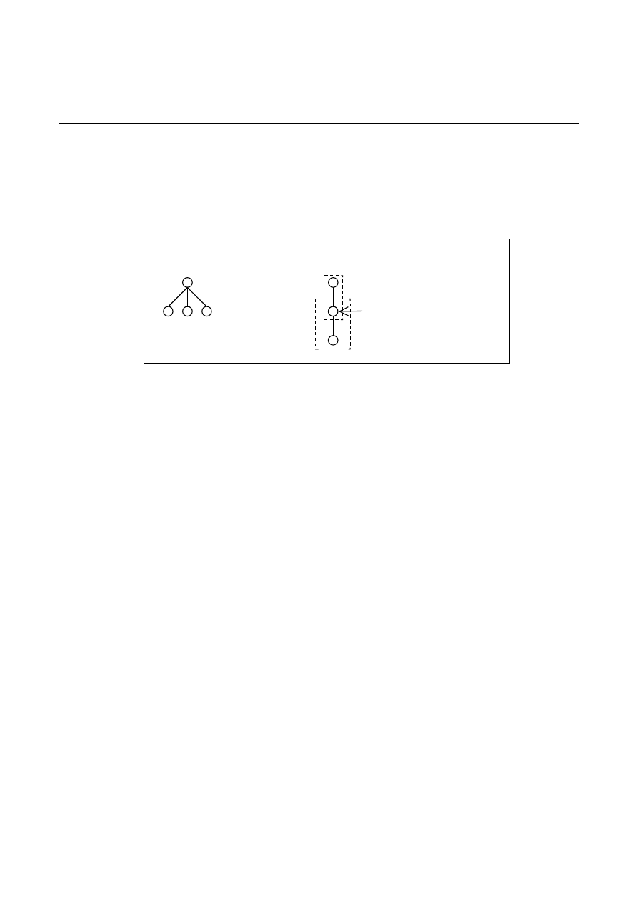
the  maximum controlled axes of a path.  The slave axis  cannot be set as  the master axis  of other 
synchronous axes. 

Second pair of synchronous axes 

Slave axis of first pair and   
master axis of second pair. 

(Example) 

This setting is available.             This setting is not available. 


Master axis 

Slave axis 

First pair of synchronous axes 


Fig. 1.6.3 (a) 


Maximum pairs of synchronous axes 

Maximum pairs of synchronous axes (maximum number of combinations for master axis and slave axis) 
are 4 pairs. 
 

Synchronous operation and normal operation   

Operation where axis synchronous control is turned on (enabled) to make a movement along the slave 
axis in synchronism with the master axis is called  a  synchronous operation. Operation where axis 
synchronous control is turned off (disabled) to move a  master axis and a  slave axis independently is 
called a normal operation. 
 
(Example) 
 

Automatic operation when the master axis is the X-axis and the slave axis is the A-axis: 


In synchronous operation, both the X-axis and the A-axis are moved according to the programmed 
command Xxxxx for the master axis. 


In normal operation, the master axis and the  slave axis are moved  independently as in the case of 
normal CNC control. The programmed command Xxxxx makes a movement along the X-axis. The 
programmed command Aaaaa makes a movement along the A-axis. The programmed command 
Xxxxx Aaaaa makes movements along the X-axis and A-axis at the same time. 

 
The mode of operation can be switched between synchronous operation and normal operation by an input 
signal, or synchronous operation can be performed at all times. Which mode to use can be set using bit 5 
(SCAx) of parameter No. 8304. 


Switching between synchronous operation and normal operation by using an 
input signal 

When bit 5 (SCAx) of parameter No. 8304 is set to 0 for the slave axis, the signals for selecting the axis 
for axis synchronous control SYNC1 to SYNC8<Gn138> / signals for selecting the manual feed axis for 
axis synchronous control SYNCJ1 to SYNCJ8<Gn140> is used to switch between synchronous operation 
and normal operation. When SYNC/SYNCJ = 1, synchronous operation is selected. When SYNC/SYNCJ 
= 0, normal operation is selected. 
Synchronization error compensation cannot be used when the mode of operation is switched between 
synchronous operation and normal operation. 

B-64693EN-1/01


1. AXIS CONTROL


- 187 - 

  CAUTION 


To switch between synchronous operation and normal operation, command the 
relevant M code (set to the parameter No. 8337 or 8338). 

 
The  synchronous operation and the  normal operation can be changed by setting each  signal SYNC  / 
SYNCJ by each operation of automatic operation and manual operation. 


Setting for using synchronous operation at all times 

When  bit  5 (SCAx) of parameter No. 8304 for the slave axis is set to 1, synchronous operation is 
performed at all times, regardless of the setting of the signal SYNC/SYNCJ. 
 

Axis synchronous control status signals 

During axis synchronous control, the axis synchronous control status signals SYNO1 to SYNO8<Fn532> 
becomes 1. However, this signal might not be the same as the status of signal SYNC / SYNCJ or bit 5 
(SCAx) of parameter No. 8304. For instance, this signal is “0” during emergency stop, servo alarm, servo 
off, and controlled axes detach. 
 

  - 

Synchronous control axis name 

There is no problem whether the name of a master axis and the name of a slave axis is the same or not. 


Restrictions on using the same name for the master axis and slave axis 

If the same axis name is assigned to the master axis and slave axis, manual operation only is allowed in 
normal operation. Automatic operation cannot be performed. 


Axis name subscript and extended axis name 

If the axis name of synchronous axis is set by using the axis name subscript or the extended axis name, 
the axes can be distinguished from each other on the screen display, or which of those axes issued an 
alarm can be identified. 
The axis name subscript is set by the parameter No. 3131, and the extended axis name is set by the bit 0 
(EEA) of parameter No.1000, parameter No.1025, and parameter No.1026. 
 

Current position display screen 

On a screen such as the current position display screen, a slave axis is also displayed.  The display of a 
slave axis can be disabled by the following parameter settings.   


Set the last to the  slave axis of parameter  No.3130 (axis display order for current position display 
screens). 


Set 1 to bit 0 (NDPx) of parameter No.3115 and bit 1 (NDAx) of parameter No.3115. 


Example 


In the example below, movements along the X1-axis and X2-axis are made in synchronism with the 
XM-axis. 


Table 1.6.3 (a) 

Axis name 

indication 

Controlled 

axis number 

Axis name 

No. 1020 

Subscript 

No.3131 

Master axis number 

No.8311 

Operation 

XM 

88 

77 


89 


X1 

88 

49 

A movement is made in 
synchronism with the XM-axis. 

X2 

88 

50 

A movement is made in 
synchronism with the XM-axis. 


1. AXIS CONTROL


B-64693EN-1/01


- 188 - 

When one master axis has multiple slave axes, synchronization error compensation, synchronization 
establishment, and synchronization error check are performed for each slave axis independently. 
 

Slave axis mirror image 

By setting parameter No. 8312, a mirror image can be applied to a slave axis placed in synchronous 
operation.  When the mirror image function is enabled, the direction in which the absolute and relative 
coordinates change is the same as for the machine coordinates. 
At this time, synchronization error compensation, synchronization establishment, synchronization error 
check, and correction mode cannot be used. 
The mirror image set by bit 0 (MIRx) of parameter No. 0012 cannot be applied to the slave axis. Because 
this mirror image differs from the mirror image set by bit 0 (MIRx) of parameter No. 0012, it does not 
affect mirror image  signals MI1 to MI8  <Gn106> or mirror image check  signals MMI1 to MMI8 
<Fn108>. 
 

Automatic slave axis parameter setting 

Axis synchronous control involves parameters which must be set to the same values for the master axis 
and slave axis. (See the parameter list in "Parameters which must be set to the same value for the master 
and slave axes" to appear later. If bit 4 (SYPx) of parameter No. 8303 is 1, setting values for these 
parameters for the master axis causes the same values to be set to the parameters for the slave axis. For 
details, see Subsection “Automatic Slave Axis Parameter Setting”. 
 

1.6.4 

Reference Position Establishment 

1.6.4.1 

Procedure of reference position establishment 

The procedure of reference position establishment using grid points is as follows. 


Set grid position difference of 

master axis and slave axis. 

(See 1.6.4.2) 

Establish reference position.


Adjust balance. 

(See 1.6.4.3) 

(See 1.6.4.4) 

End 


Fig. 1.6.4.1 (a) 


Absolute position detection 

When the absolute  position  detection  is used, do not execute the setting the zero point using MDI 
operation  that sets bit 4 (APZ) of parameter  No.1815  directly  for  the re-setting of the reference point 
establishment  in the maintenance work. After setting up the  deceleration dog or  clarifying  the start 
position for reference position establishment, perform the setting the zero point of the absolute position 
detector. 
By setting bit 7 (SMA) of parameter No. 8302 is set to 1, when the bit 4 (APZx) of parameter No. 1815 
for an axis in synchronous operation is set to 0, and APZx of the pairing axis in synchronous operation is 
also set to 0. 

B-64693EN-1/01


1. AXIS CONTROL


- 189 - 


Reference point setting with mechanical stopper 

If the reference  point  setting with mechanical stopper  is used, see Subsection “Reference point  setting 
with mechanical stopper”. 
 

Distance coded linear scale interface, Linear scale with distance-coded 
reference marks (serial) 

If the distance coded linear scale interface or the linear scale with distance-coded reference marks (serial) 
is used, see Subsection “Distance coded linear scale interface, Linear scale with distance-coded reference 
marks (serial)”. 
 

Normal operation 

The reference point establishment by the normal operation is the same as a usual axis. 
 

1.6.4.2 

Setting of grid position 

When manual reference position return operation is performed along axes under axis synchronous control, 
the machine is placed at the reference position on the master axis and slave axis according to the same 
sequence as for normal reference position return operation. 
The sequence is the same as the grid method for one axis only. However, only the deceleration signal for 
the master axis is used. When the deceleration signal is set to 0, the machine gradually stops along the 
master axis and slave axis, and then an FL feedrate is set. When the deceleration signal is set to “1”, the 
machine moves to a grid position along each of the master axis and slave axis, then stops. 
 

If the grid of master axis and slave axis is as follows, master axis stop at A and slave axis stop at B.   


Grid of master axis 

Direction of manual reference position return 

Signal *DEC of master axis 

A     B 

Grid of slave axis 


Fig. 1.6.4.2 (a) 


1. AXIS CONTROL


B-64693EN-1/01


- 190 - 

NOTE 


When the grid position difference between the master axis and slave axis is 
large, a reference position shift may occur, depending on the timing of the *DEC 
signal set to “1”. In the example below, the shift along the slave axis is so large 
that the position shifted one grid point from the actual reference position is 
regarded as the reference position. 


*DEC 


Master axis feedrate 


Master axis grid 


Slave axis feedrate 


Slave axis grid 


Actual reference position 

Stop at position shifted one grid point 

(Example)  When the reference position on the slave axis is shifted one grid point 

Actual reference position 


Before axis synchronous control can be performed, the reference position (grid position) on the slave axis 
must be adjusted to the reference position on the master axis. 
If the grid position difference of the master axis and the slave axis is set to the parameter by either of the 
following methods, the master axis  and the slave axis  can be stopped at the grid position of the master 
axis. 


Automatic setting for grid position matching 


Reference position shift function 


Automatic setting for grid position matching 

The automatic  setting for grid  position  matching  can be automatically  set the reference counters (grid 
positions)  difference  in parameter No.8326, and the CNC automatically adjusts the reference positions 
(grid positions) of the master axis and slave axis. The operation procedure is as follows. 
1.


Select the synchronous operation. 

2.


Set the following parameters. 
No.1844=0  


: Distance to the first grid point 


(NOTE 1) 

No.1850=0  


: Amount of grid shift and reference position shift 

(NOTE 1) 

Bit4 (SFDx) of No.1008 =0 

: Reference position shift functions is disabled.   

(NOTE 1) 

Bit0 (ATEx) of No.8303 =1 

: Automatic setting for grid positioning is enabled. 

(NOTE 2) 

Bit1 (ATSx) of No.8303 =1 

: Automatic setting for grid positioning is started. 

(NOTE 2) 

If bit 5 (APCx) of No.1815 =1, bit 4 (APZx) of No.1815 =0 

3.


Turn off the power then turn on the power. 

4.


Set the REF mode (or JOG mode in the case of reference position setting without dogs), and make 
movements in the reference position return direction along the master axis and slave axis. 

5.


The movements along the master axis and slave axis automatically stop, and a grid difference value is 
set in parameter No. 8326. At this time, bit 1 (ATSx) of parameter No. 8303 is set to 0, and the 
power-off request alarm PW0000, “POWER MUST BE OFF” is issued. Turn off the power then turn 
on the power again. 


B-64693EN-1/01


1. AXIS CONTROL


- 191 - 

NOTE 

1  This parameter is set to the all synchronous axes. 
2  This parameter is set to the slave axis. 
3  Parameter setting 
 

When bit 1 (ATSx) of parameter No. 8303 is set, bit 4 (APZx) of parameter No. 
1815 and parameter No. 8326 for the master axis and slave axis are set to 0. 


When the operator sets parameter No. 8326 (MDI, G10L50), bit 0 (ATEx) of 
parameter No. 8303 is set to 0. 

4  This function cannot be used together with the reference position shift function. 


Reference position shift function 

If the reference position shift function is used, set the following parameters after the parameter No.8326 is 
set automatically by the operation procedure of the automatic setting for grid position matching. 

Bit4 (SFDx) of No.1008 = 1 


: Reference position shift function is enabled.    (NOTE 1) 

No.1850 = Amount of parameter No.8326: Amount of reference position shift 


(NOTE 2) 

No.8326 = 0   


: Reference counters difference between synchronous axes 


(NOTE 2) 


NOTE 

1  This parameter is set to the all synchronous axes. 
2  This parameter is set to the slave axis. 


1.6.4.3 

Reference position establishment 

The procedure of reference position establishment is as follows. 
1.


Select the synchronous operation. 

2.


When the reference position is shifted, add the shift amount to parameter No.1850 (Amount of grid 
shift and reference position shift) of the all synchronous axes. 

3.


If bit 5 (APCx) of parameter No.1815 is set to 1, set 0 to bit4 (APZx) of parameter No.1815. 

4.


Turn off the power then turn on the power. 

5.


Perform the manual reference position return. 


Reference position return operation of low-speed type 

When  bit 4 (SLR) of parameter No. 8305 is set to 1, if G28 is specified for an axis under axis 
synchronous control for which the reference position is not established, reference position return 
operation of low-speed type is performed.


1.6.4.4 

Balance adjustment 

The synchronous axes should be adjusted the balance because multiple motors are cooperatively driven. 
The procedure of balance adjustment is as follows.   
1.


Stop the synchronous  axes at one side (See  Fig.  1.6.4.4  (a)  Measuring position 1), and record the 
absolute coordinate of slave axis. This coordinate value is assumed the coordinate value A. 

2.


Terminate synchronous status, and select the normal operation. 

3.


Move the slave axis by manual handle feed so that the actual current value in the servo tuning screen 
may become near. 

4.


Straightness of synchronous axes is adjusted if necessary. Adjust the position of slave axis by manual 
handle feed  while confirming  the measured  straightness  and  the actual current value in  the servo 
tuning screen. The aim of actual current value in  the servo tuning screen  is 5%-10%  of the rated 
current value. 

5.


Select the synchronous operation. The following procedures are performed by synchronous operation. 

1. AXIS CONTROL


B-64693EN-1/01


- 192 - 

6.


Record the absolute coordinate of slave axis. This coordinate value is assumed the coordinate value B. 
(See  Fig.  1.6.4.4  (b))  Add the value of “coordinate  value B -  coordinate  value A”  to parameter 
No.1850 of slave axis. 

7.


If bit 5 (APCx) of parameter No.1815 is set to 1, set 0 to bit4 (APZx) of parameter No.1815. 

8.


Turn off the power then turn on the power. 

9.


Perform the manual reference position return. 

10.


Stop the synchronous axes at other side (See Fig. 1.6.4.4 (a) Measuring position 2), and confirm the 
actual current value in the servo tuning screen. If the value is different, adjust the position of the slave 
axis by using the pitch error compensation, the straightness compensation, and the external machine 
coordinate system shift, etc. 

11.


Move the synchronous axes to the center (See Fig. 1.6.4.4 (a) Measuring position 3), and confirm the 
actual current value in the servo tuning screen. If the value is different, adjust the position of the slave 
axis by using the pitch error compensation, the straightness compensation, and the external machine 
coordinate system shift, etc. 


Measuring position 2 

X (Master axis) 

A  (Slave axis) 

Measuring position 3 

Measuring position 1 


Fig. 1.6.4.4 (a)  Measuring position 


Master axis 

Slave axis 

Coordinate value A 
Position of slave axis when balance adjustment starts 

Coordinate value B 
Position  that balance of synchronous axes was 
adjusted by manual handle feed of slave axis 

Position of master axis when balance adjustment starts 


Fig. 1.6.4.4 (b)    Position of balance adjustment 


B-64693EN-1/01


1. AXIS CONTROL


- 193 - 

Pitch error compensation and straightness compensation 

The pitch error compensation  and  the  straightness compensation are executed independently on the 
master axis and the slave axis. 
 

External machine coordinate system shift 

  By setting bit 7 (SYEx) of parameter No. 8304 to 1 to the slave axis, the slave axis can be shifted by the 
same amount as specified for the master axis when external machine coordinate system shift is specified 
by external data input/output for the master axis in synchronous control. When bit 7 (SYEx) of parameter 
No. 8304 is set to 0, the external machine coordinate system shift is executed independently on the master 
axis and the slave axis. 
 

1.6.4.5 

Maintenance 

When motor is exchanged, perform the recovery operation from setting of grid position. 
When the parameter is lost by an unexpected situation,  restore  the backup data of the  parameter  and 
perform  only reference position establishment  again.  Thus, the reference position  becomes the same 
position of last time. 
 

1.6.4.6 

Reference point setting with mechanical stopper 

The procedure of reference position establishment by the reference point setting with mechanical stopper 
is as follows. 
1.


If  the  balance adjustment is necessary,  execute the balance adjustment by the  procedure 2-4 in 
Subsection "Balance adjustment".  If  the balance adjustment is completed,  select the synchronous 
operation. 

2.


Perform the reference position establishment by the reference point setting with mechanical stopper. 


1.6.4.7 

Distance coded linear scale interface and linear scale with 

distance-coded reference marks (serial) 

The  procedure  of reference position establishment  by the distance coded linear scale interface  or the 
linear scale with distance-coded reference marks (serial) is as follows. 
1.


If  the  balance adjustment is necessary,  execute the balance adjustment by the  procedure 2-4 in 
Subsection "Balance adjustment".  If  the balance adjustment is completed,  select the synchronous 
operation. 

2.


Perform the reference position establishment by the distance coded linear scale interface or the linear 
scale with distance-coded reference marks (serial). 

3.


If the reference position of the master axis and the slave axis shifts, add the shift amount to parameter 
No.1883 and No.1884. Thus, the reference position  of the master axis and slave axis becomes the 
same position. 


NOTE 

1  It is also possible to use the master axis or the slave axis in the opposite 

direction, in the distance coded linear scale interface and the linear scale with 
distance-coded reference marks (serial). 

2  To use the distance coded linear scale interface and the linear scale with 

distance-coded reference marks (serial), the option "Linear scale I/F with 
absolute address reference mark" is required. 


Content      ..     27      28      29      30     ..