TM920 Diagnostics and service (2018) - page 3
Troubleshooting
Recommended procedure for replacing a PC:
• Check product ID of replacement device.
• Remove supply voltage.
• Remove hard drive and CompactFlash card.
• Install hard drive and CompactFlash card on new device as
needed.
• Reinstall Technology Guard on the new device.
• Remove plug-in cards.
• Insert plug-in cards in new device as needed.
• Set node number switches.
• Install backup battery (included in delivery) on replacement de-
vice.
• Restore power supply.
• Wait for startup to complete.
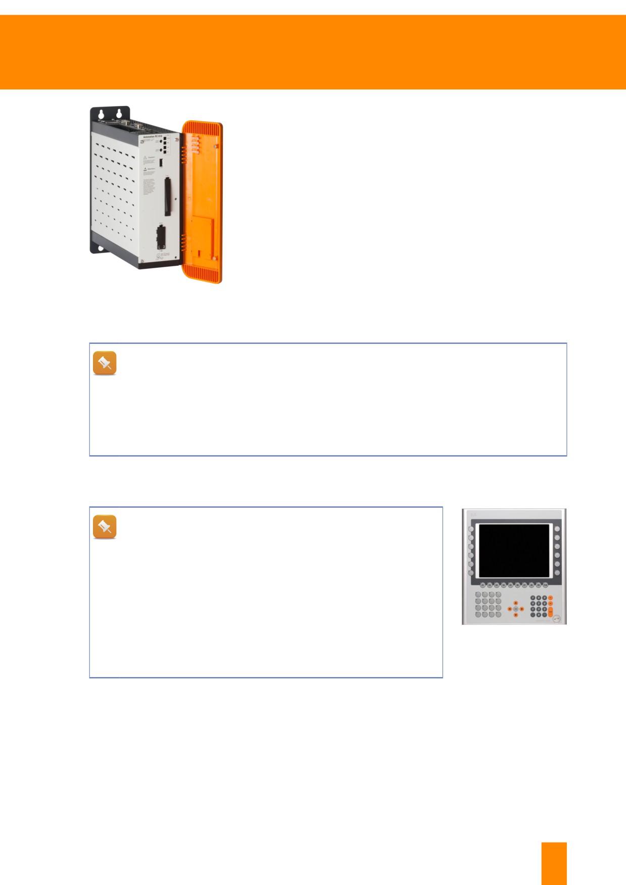
Figure 80: Automation PC 910
What should be considered before replacing a B&R PC?
Be sure to note the BIOS settings before replacing a PC. These must then be set identically
in the replacement device. A description of how to do this can be found in the user's manual
of the respective PC.
If interface cards are built into the PC then they should be built into the new device in the same
position. If dongles are used to protect software then they should be moved to the new PC.
Automation Panel
An Automation Panel is a display device and can only be used in connection with an Automation PC.
Does the new touch screen have to be calibrated after replacing
the module?
Touch screen recalibration may be necessary after replacing an Au-
tomation Panel. On Windows systems, this can be done in the Con-
trol Panel.
On devices with hardware keys, the key configuration is stored on
the PC. When the PC is replaced, the key configuration must be
transferred to the new PC. This can be done using the "Automation
Device Interface" (ADI) in the Control Panel. The ADI software is
Figure 81: Automation
described in the user's manual of the PC.
Panel 5AP981.1043-01 with
touch screen and hardware
keys
7.2.4 Motion control - Drive systems
Drives generally provide a mains connection and connections to the motor. Drives must only be replaced
when the power is turned off.
After replacing the drive, check the grounding of the drive and the cable, the wiring of the digital inputs (E-
stop, quick stop, trigger, enable, limit switch inputs) and the torque of the fastening screws for ACOPOS-
multi modules.
TM920 - Diagnostics and service
63
Troubleshooting
Additional information about this is provided in the respective user's manual.
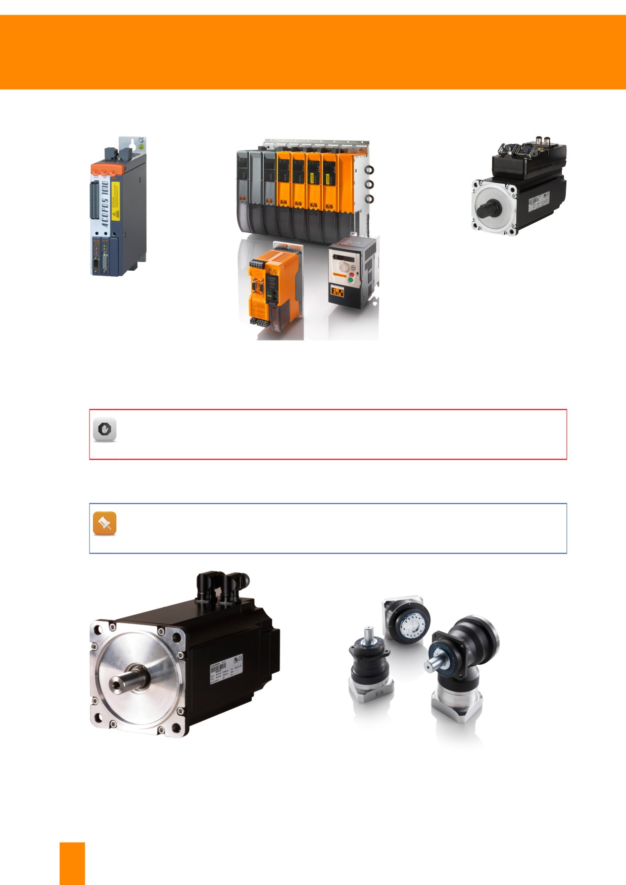
Figure 84:
ACOPOSmotor
Figure 82:
ACOPOS
Figure 83: ACOPOSmulti (in back), ACOPOSmicro (on
the left) and ACOPOSinverter
User's manuals include danger notices with important information about how to use the respec-
tive systems. The instructions in the user's manuals must be followed.
7.2.5 Motion control - Motors
B&R motors and 3rd-party motors (motors from other manufacturers) are handled entirely dif-
ferently. The following applies to B&R motors.
Figure 85: 8LSA56.E0060D000-0 - Synchronous
motor, size 5, with EnDat encoder
Figure 86: Premium planetary gearboxes
64
TM920 - Diagnostics and service
Troubleshooting
B&R motor type
Description of the document
8LVA, 8JS, 8LT, 8MS, etc.
"Data sheet 8LVA", "Data sheet 8JS", etc.
Stepper motors
"User's manual for stepper motors"
Planetary gearbox
"System overview of planetary gearbox"
ACOPOSmotor
"User's manual for decentralized motion control"
Table 6: Overview of user's manuals for motors on the B&R website
7.2.6 Integrated safety technology
Safe I/O modules, SafeLOGIC, SafeLOGIC-X
SafeLOGIC controllers handle safe evaluation of data from compo-
nents such as light curtains or E-stop buttons.
The user's manual for integrated safety technology de-
scribes exactly how to handle safety-related components
and maintenance scenarios. All safety notices and danger
specifications must be followed.
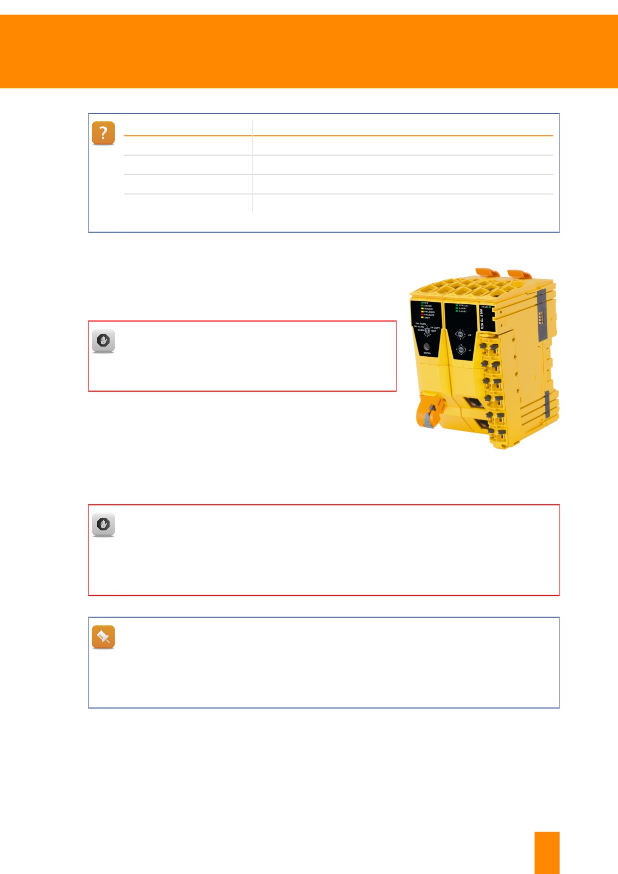
Figure 87: X20SL8100 - SafeLOGIC
In the user's manual for integrated safety technology, the technical data provided for the re-
spective SafeLOGIC controllers includes descriptions of maintenance scenarios.
The description of SafeLOGIC controller SL8100, for example, can be found in chapter 2 "X20
System", subchapter 2.6.7.2.6 "Maintenance scenarios". These scenarios include aspects like
replacing a module.
How are safety-related sensors, actuators and drives connected?
Instructions on connecting safety-related sensors, actuators and drives with the STO function
can also be found in the user's manual for integrated safety technology. Information about
switching on safety-related actuators can be found in chapter 2 "X20 modules" under connec-
tion descriptions of secure digital output modules.
TM920 - Diagnostics and service
65
Troubleshooting
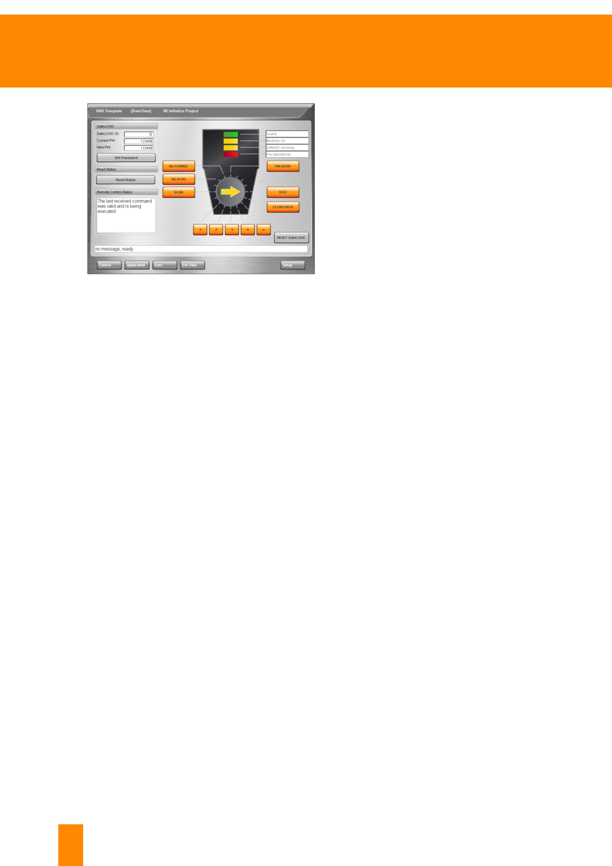
Remote Control dialog box
SafeLOGIC-X controllers have neither selector
switches nor confirmation buttons. Instead, a Re-
mote Control dialog box can be embedded in the
HMI application by the machine manufacturer. This
can be used, for example, to confirm a replaced
module. The same dialog box can also be used for
the current model of the X20SLxxxx series.
Figure 88: Remote Control dialog box embedded in the HMI
application
"$safety" logger file
The Logger (6.1 "SDM functions" on page 40) also saves important information related to the state of
the safety controller. These files can be stored locally when Logger file "$safety" is selected.
Further information:
•
6.3 "Saving Logger files" on page 45
66
TM920 - Diagnostics and service
Troubleshooting
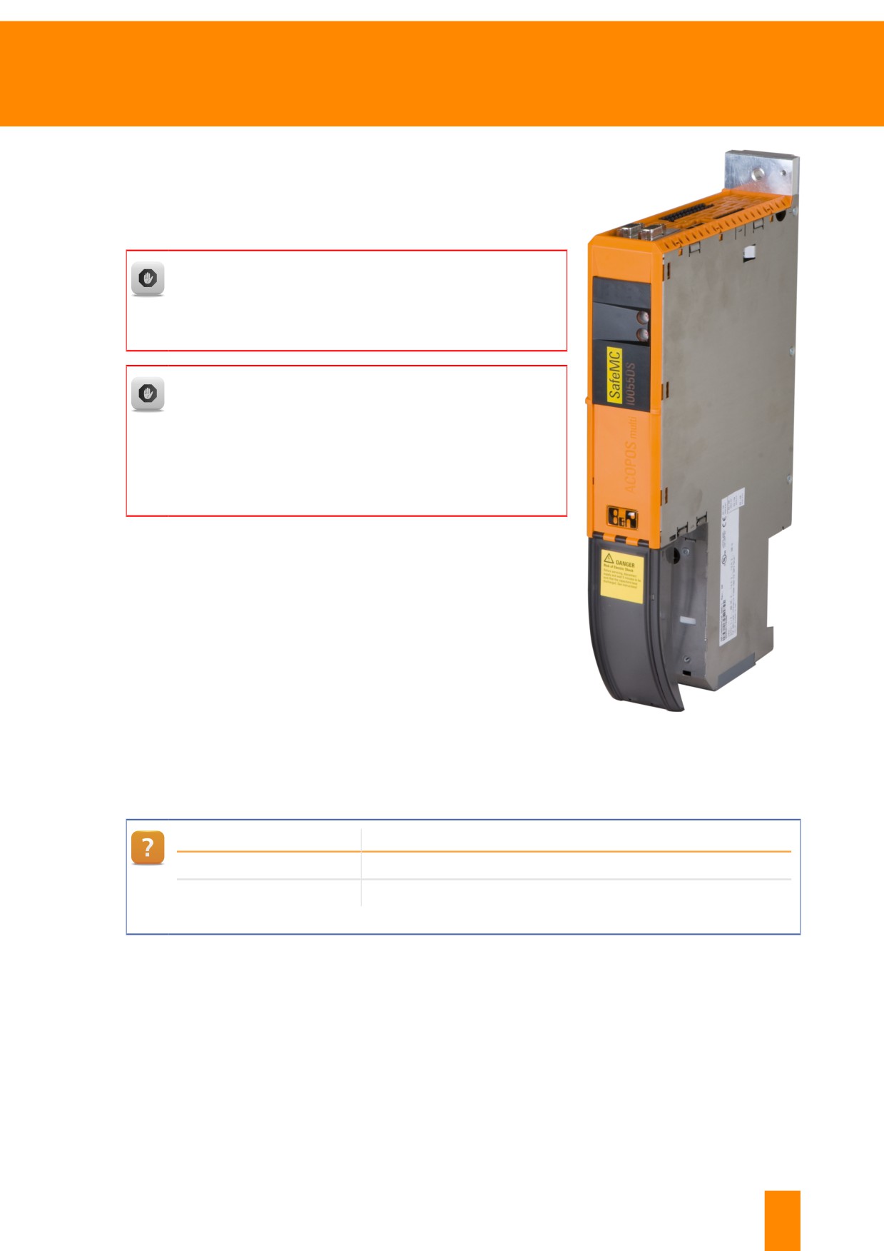
ACOPOSmulti with SafeMOTION
In contrast to standard ACOPOSmulti inverter modules, ACOPOS-
multi modules with SafeMOTION are able to evaluate encoder sig-
nals internally with regard to safety.
The user's manual for ACOPOSmulti SafeMOTION de-
scribes exactly how to handle safety-related components
and maintenance scenarios. All safety notices and danger
specifications must be followed.
The maintenance scenarios are described in the user's
manual for SafeMOTION.
Maintenance scenarios are described in chapter 6 "Safety
technology", subchapter 6.7.5. Included are descriptions of
ACOPOSmulti SafeMOTION inverter module replacement,
motor replacement and updates.
Figure 89: 8BVI0014HCDS.000-1 -
ACOPOSmulti SafeMOTION inverter
modules
System
Title of user's manual
Safety technology
"Integrated safety technology user's manual"
Safe motion control
User's manual for SafeMOTION
Table 7: Overview of user's manuals for safety on the B&R website
TM920 - Diagnostics and service
67
Troubleshooting
7.3 Starting up again and functional testing
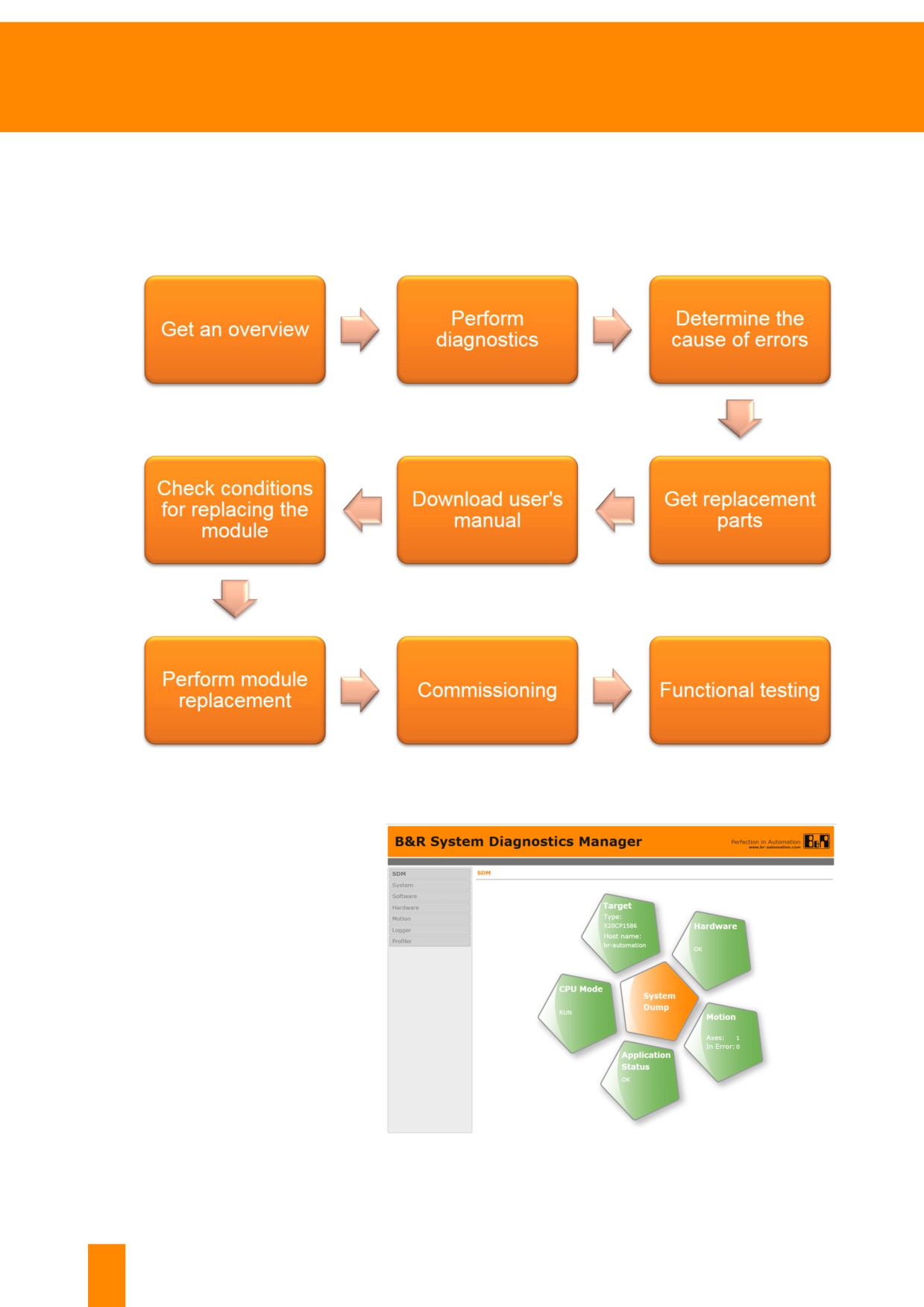
The following step sequence can be used when replacing a defective module. System Diagnostics Man-
ager is available as support for diagnostics.
Figure 90: Required steps for replacing a module
The status of System Diagnostics
Manager in the image shows that
there are no more errors identified
by the control system.
Functional testing must be used
to ascertain whether the machine
runs properly.
Figure 91: System Diagnostics Manager start page
68
TM920 - Diagnostics and service
Troubleshooting
Embedded SDM in the HMI application
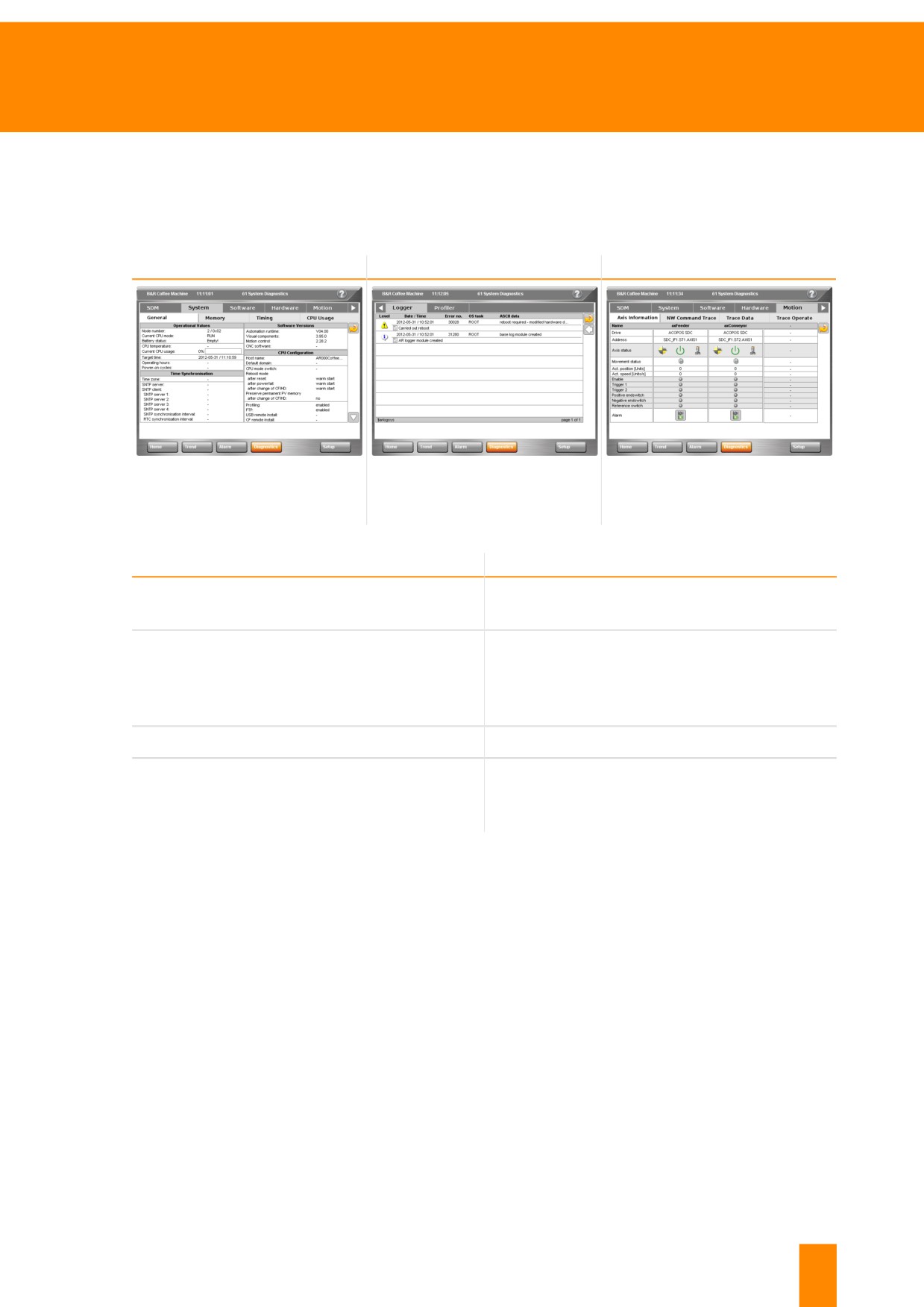
Machine manufacturers are able to integrate the SDM right in the HMI application. The same functions
are available as those provided when running the SDM in a web browser. Just the display of diagnostic
pages differs a bit from the embedded SDM version.
System overview
System logger
Drive technology diagnostics
Figure 92: SDM system overview
Figure 93: SDM system logger
Figure 94: SDM drive technology
diagnostics
Description
Information source
• Machine manual
Safety and general notices
• B&R user's manuals
• HMI application
• LED status indicators
Status of B&R controller, I/O modules and drives
• System Diagnostics Manager
• Runtime Utility Center
Turning on and starting up the machine
• Machine manual
• HMI application
Machine process function
• Machine manual
• mapp technology WebXs24
Table 8: Information sources for starting up again and function testing
24 If the machine application uses mapp technology, then there is a web-based diagnostics for the mapp
functions.The machine manufacturer, however, must document in the machine manual which mapp com-
ponents are responsible for controlling a certain machine function.
TM920 - Diagnostics and service
69
Backing up and restoring
8 Backing up and restoring
Software updates and software installation packages are only available from the machine manufacturer.
A software update is only necessary if there is a software error or if changes have been made to the
functions in the software.
The following chapters describe how to back up and restore the CompactFlash card and how to create
your own Instruction Lists using the Runtime Utility Center.
There are many conditions dictating whether or not the software on a machine controller can be
backed up and restored. In many cases, the source files for the control software are not stored
on the CompactFlash card or on the internal Flash memory.
Battery-backed data from the machine controller is not applied when backing up and restoring
data. Backing up data requires knowledge of the control software. All necessary information is
provided by the machine manufacturer and the maintenance manual for the machine.
8.1 Backing up and restoring using the Runtime Utility Center
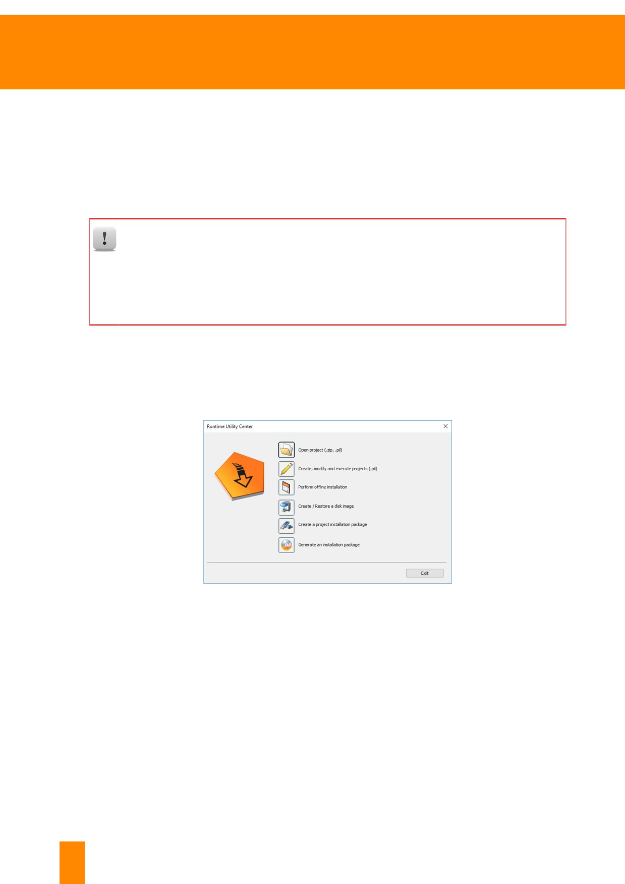
The Runtime Utility Center is a system tool that provides a range of utilities for diagnostics and service
on B&R controllers. The installation program for the Runtime Utility Center is included in the Automation
Studio installation or can be downloaded separately from the B&R website.
Figure 95: Runtime Utility Center - Start page
The most important functions are:
• Performing service functions via an online connection to the controller
• Variable functions for backing up and restoring process variables
• Creating individual Instruction Lists for testing and installation procedures
• Backing up and restoring a CompactFlash/CFast card
• Offline installation of a control project on a CompactFlash/ CFast card
• Creating project installation packages for USB installation
• Custom mode allows the creation of a user-defined user interface
70
TM920 - Diagnostics and service
Backing up and restoring
How can I open the Runtime Utility Center help documentation?
The Runtime Utility Center contains complete help documentation. This help documentation is
opened by pressing the "F1" key . The Runtime Utility Center must be opened before doing
this. The following entries provide additional important information about using the Runtime
Utility Center.
Runtime Utility Center \ Start page
Runtime Utility Center \ Operation \ The Workspace
Runtime Utility Center \ Operation \ Commands \ Establish connection, wait for new connection
Runtime Utility Center \ Operation \ Commands \ PLC Info \ Logger
Downloading the Runtime Utility Center
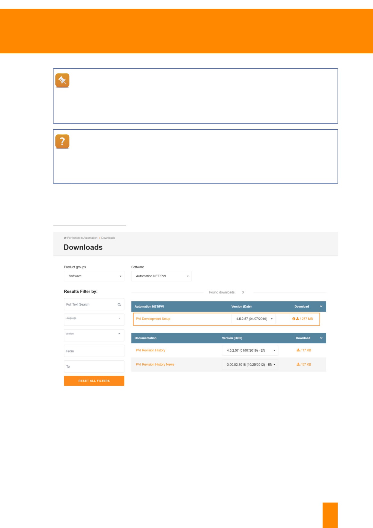
The Runtime Utility Center is part of the PVI development setup and can be downloaded from the B&R
website:
Figure 96: Downloads section, product groups filter "Software"→"Automation NET/PVI"
TM920 - Diagnostics and service
71
Backing up and restoring
Installing the Runtime Utility Center
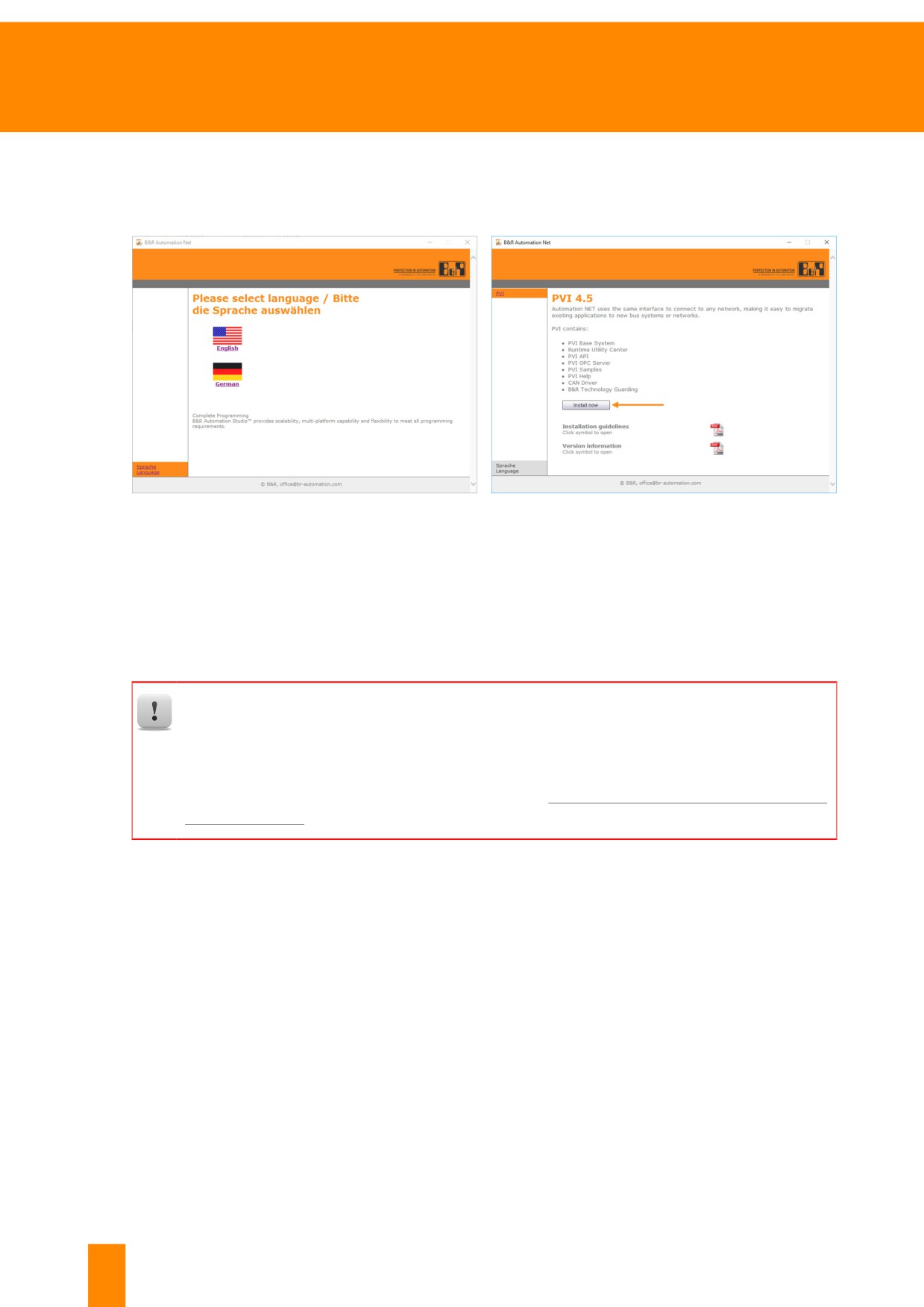
The downloaded installation package must be extracted before installation. The installation program can
then be started. No changes have to be made during the installation for use of the Runtime Utility Center.
Figure 97: Select a language
Figure 98: Click on "Start installation"
8.1.1 Backing up and restoring a CompactFlash card
The following section will demonstrate the steps necessary to back up and restore the machine con-
troller's CompactFlash card. When backing up, an image of the CompactFlash card is created and saved
to the PC. When restoring, an existing image is copied to the CompactFlash card.
When restoring an image, all of the data stored on the CompactFlash card will be lost. A con-
ventional card reader is required to back up and restore a CompactFlash card.
Backing up and restoring a CompactFlash card only involves the contents of the CompactFlash
card25. Process data in the battery-backed memory area is not taken into account. These data
can be backed up using the Runtime Utility Center (8.1.4 "Online connection and Instruction
Lists" on page 78).
Procedure
The Runtime Utility Center is started via the Windows start menu.
In order to back up and restore the data on a CompactFlash card, it must first be connected to the PC
using a card reader. By clicking on menu option "Create / restore a drive image", the dialog box for
backing up and restoring the CompactFlash card is opened.
25 Configuration and program modules on systems without CompactFlash cards are stored directly in the CPU's
memory. These contents can only be backed up using an Instruction List in the Runtime Utility Center.
Program modules can be uploaded using the "Module functions" category.
72
TM920 - Diagnostics and service
Backing up and restoring
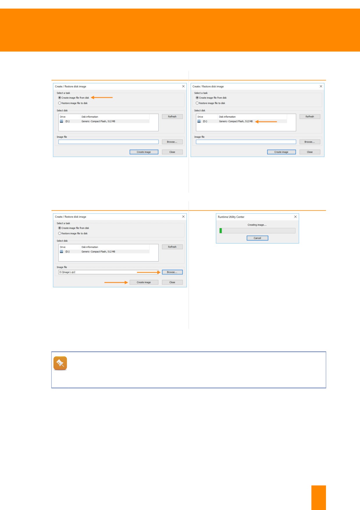
Backing up a CompactFlash card
Step 1
Step 2
Figure 99: Select "create image from disk"
Figure 100: Select CompactFlash card from the list
The connected drives are reloaded via the "Re-
fresh" button.
Step 3
Step 4
Figure 102: An image file of the CompactFlash is created
Figure 101: Specify storage location and click on "Create
image"
The memory location of the image file is selected
by clicking on the "Browse" button.
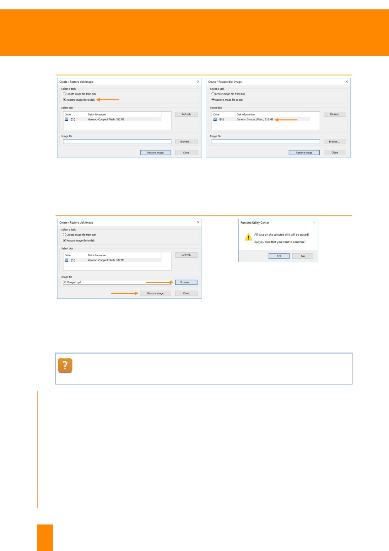
Restoring a CompactFlash card
Which CompactFlash card is suitable for recovery?
The CompactFlash card can only be restored on a CompactFlash card that is the same size or
larger. This function is limited to CompactFlash cards from B&R.
TM920 - Diagnostics and service
73
Backing up and restoring
Step 1
Step 2
Figure 103: Select "restore image to disk"
Figure 104: Select CompactFlash card from the list
The connected drives are reloaded via the "Re-
fresh" button.
Step 3
Step 4
Figure 106: When restoring an image, all data on the
CompactFlash card will be deleted Proceed?
Figure 105: Select image file and click on"Restore image"
The memory location of the image file is selected
by clicking on the "Browse" button.
Runtime Utility Center \ Creating a list \ Data storage medium \ CompactFlash functions \ Gen-
erating CompactFlash
Exercise: Backing up the CompactFlash card
For precautionary reasons, create an image file of the CompactFlash card's contents. This image can
then be restored at a later point in time. Before turning off the CPU, refer to the LED status indicators or
the SDM to check the status of the backup battery.
1) Check the status of the backup battery
2) Turn off control CPU
3) Remove the CompactFlash card
4) Insert CompactFlash card to card reader and connect to PC
5) Start Runtime Utility Center, select "Create / Restore a disk image"
74
TM920 - Diagnostics and service
Backing up and restoring
6) Select CompactFlash
7) Select the memory location for the image
8) Create image file
8.1.2 Backing up files from CompactFlash
A CompactFlash card can contain multiple partitions. In Windows, only the "C" drive of the CompactFlash
card can be seen. Runtime Utility Center can be used to back up and restore files from the other partitions.
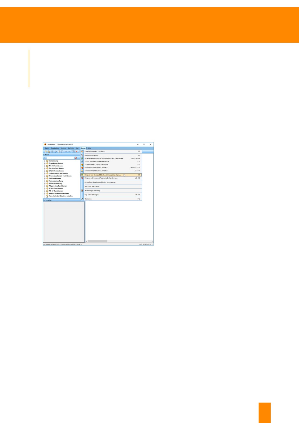
Click on menu option"Create, edit and execute projects (.pil)" to open the dialog box for backing up
the CompactFlash files.
In the Runtime Utility Center, the "Tools" tab is used
to get to option "Back up files from Compact-
Flash card / image file" where the dialog box for
saving the files can be opened.
The CompactFlash card is connected to the PC us-
ing a card reader.
Figure 107: Runtime Utility Center "Tools" \ "Backup files from
CompactFlash card" / "Back up image file"
TM920 - Diagnostics and service
75
Backing up and restoring
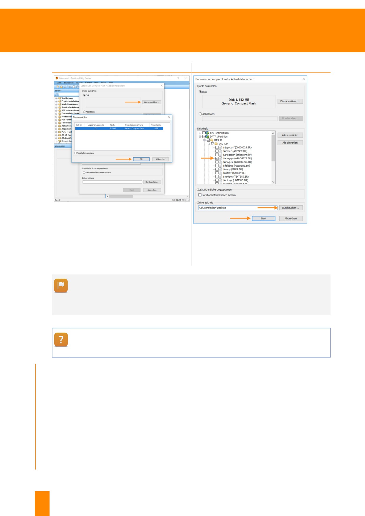
Step 1
Step 2
Figure 108: Select CompactFlash card from the list
Click on "Select disc", select CompactFlash card
and click on "OK"
Figure 109: Back up Logger file "$arlogsys" from
CompactFlash card
Select Logger file, set destination directory and
click on "Start"
The files selected will be stored in the destination directory with the same structure shown in
the selection dialog box.
The files can be copied to another CompactFlash card via tab "Extras", option"Restore files
to CompactFlash card".
Runtime Utility Center \ Operation \ Backing up \ Restoring files on CF
Exercise: Back up the Logger file from the CompactFlash card
The Logger file is stored on the CompactFlash card. While the Logger file can be uploaded using SDM,
the Runtime Utility Center offers the possibility to back up the Logger file directly from the CompactFlash
card. The Logger file name is "$arlogsys". The goal of this exercise is to find the Logger file on the
CompactFlash card and then back it up.
1) Start Runtime Utility Center
2) Select "Tools - Back up files from CompactFlash" from the main menu
3) Select CompactFlash
4) Select the Logger file "$arlogsys".
76
TM920 - Diagnostics and service
Backing up and restoring
5) Specify destination directory
6) Create file backups
The Logger file can be used by the machine manufacturer or B&R for analysis.
If the control CPU is no longer operational, the Logger file can still be backed up by the Com-
pactFlash card for further analysis by following the procedure described above.
8.1.3 Generate project installation package
Updating the control software is performed using a project installation package. Using a USB flash drive,
the software can then be transfered directly to the CPU via a DHCP/FTP server or a CompactFlash card.
The project installation package is created from a Runtime Utility Center export package provided by
the machine manufacturer.
Loading Runtime Utility Center export package
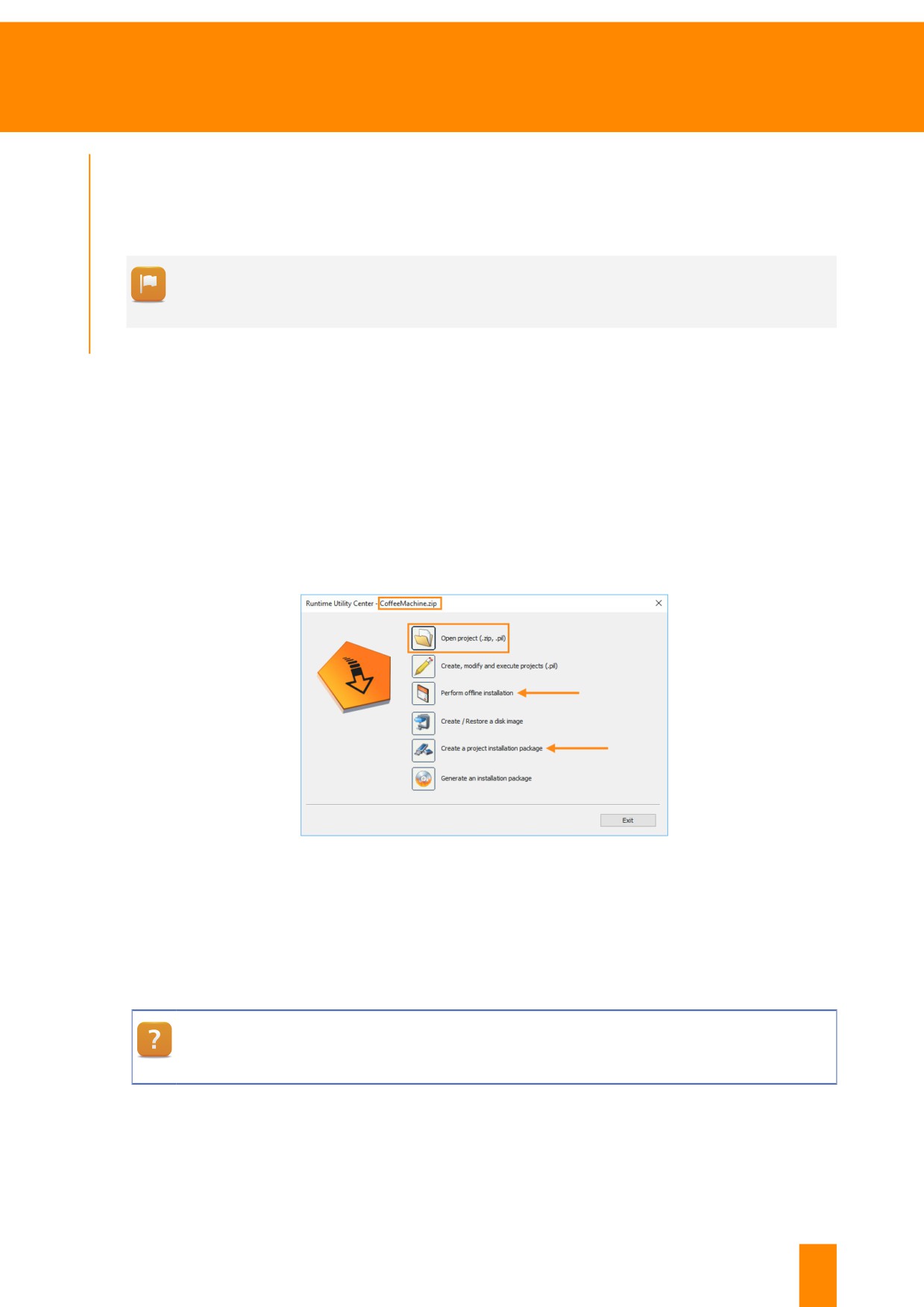
Select "Open project (ZIP, .pil)" to load the Runtime Utility Center export package. Then, the following
functions are available:
Figure 110: Runtime Utility Center start page with export file already loaded, see header of window
• Performing offline installation
This function can be used to perform an initial transfer to a CompactFlash/CFast card.
• Creating project installation package
This function can be used to create a project installation package, e.g. for USB installation.
Runtime Utility Center \ Creating a list / data medium \ Project installation
If the project installation package has been transfered to a USB flash drive, for example, this can be
inserted in the controller's USB port. The next time the controller is restarted, it checks the version of
the application and, if necessary, transfers it to the controller. However, this function has to have been
enabled in the control project.
TM920 - Diagnostics and service
77
Backing up and restoring
8.1.4 Online connection and Instruction Lists
The Runtime Utility Center provides the option to create Instruction Lists for service purposes. This
makes it possible to group multiple commands into a single list. The entire list can then be executed
as a sequence.
As with SDM,26the Ethernet interface is available for connecting to the controller. The network settings
might have to be changed on the PC, see (10.3 "Changing network settings on the PC" on page 86).
Additionally, a connection via a serial interface is supported.
What has to be considered when connecting via the serial interface?
In this case, make sure the serial interface is not already being used by the control program. A
serial cable would also be required for this. For a description of the cable construction see:10.1
"Online connection cable" on page 84.
8.1.5 Outputting data via online connection
The following section describes how to establish a connection to the control CPU using the Runtime Utility
Center. The upload of the Logger file was used as an example. Further procedures must be configured
in the same way.
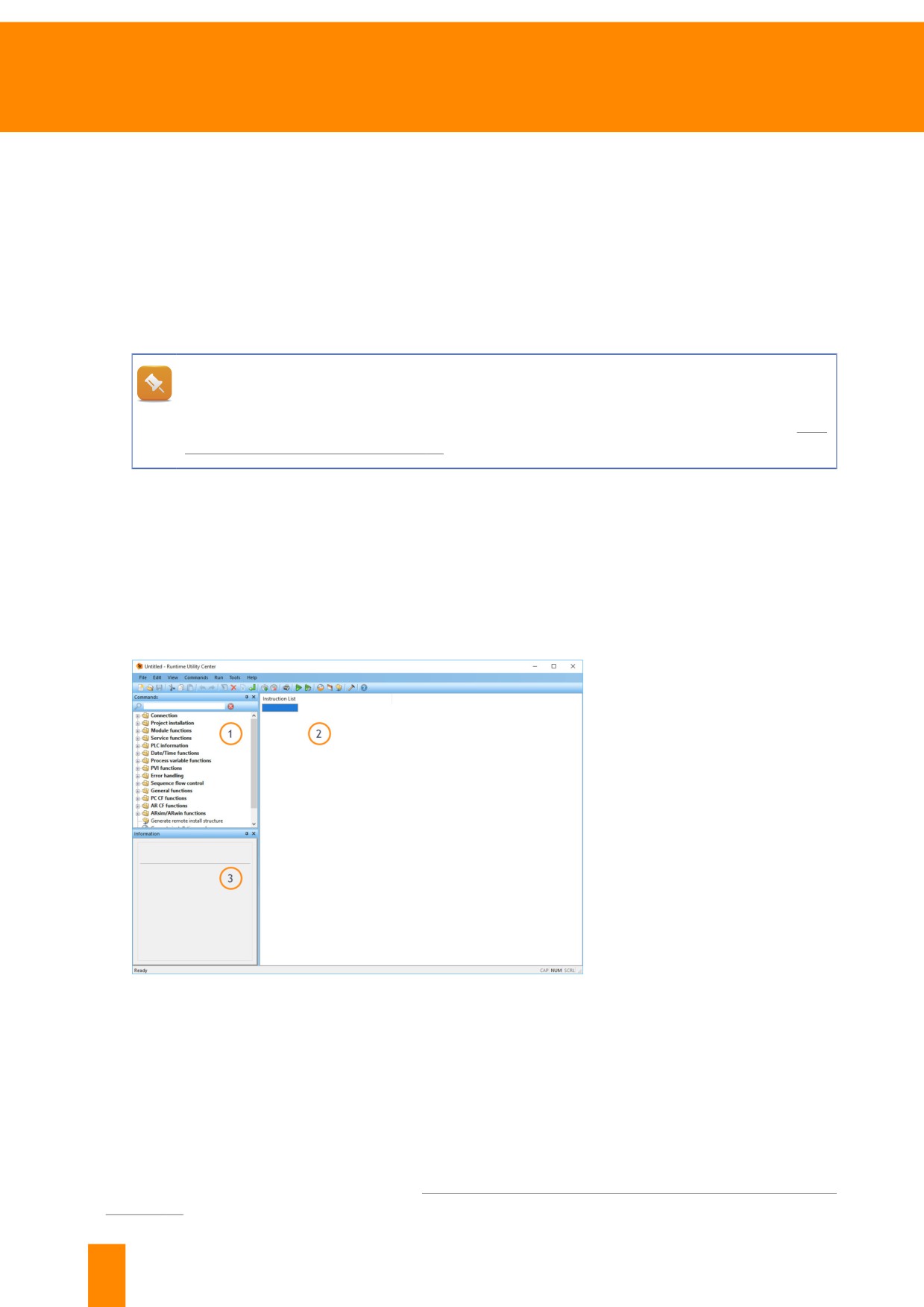
First, open the Runtime Utility Center and select menu option "Create, modify and execute projects
(.pil)". The following view is displayed:
Description of window:
1) Command set
2) Instruction List: The list of
commands to be executed
is created here
3) Short description of the
selected command
Commands are added to the In-
struction List using drag-and-drop
Figure 111: Runtime Utility Center main window
26 The Runtime Utility Center and System Diagnostics Manager offer several diagnostic options in equal mea-
sure. For a comparison of the two tools, see 10.2 "Where SDM and Runtime Utility Center can be used"
on page 84.
78
TM920 - Diagnostics and service
Backing up and restoring
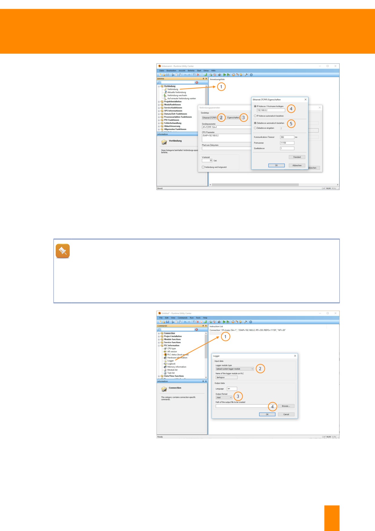
Establish the connection
Description of steps:
1) Drag command "Connec-
tion" from the command
set and drop it in the In-
struction List. The configu-
ration dialog box will open
automatically
2) Select device type "Ether-
net (TCPIP)"
3) Select "Properties"
4) "IP address / Set host-
name" and enter IP ad-
dress
5) "Select "Obtain destina-
tion address automatical-
Figure 112: Adding an Ethernet connection to the Instruction List
ly"
After completing the settings, close the dialog box by pressing "OK".
Which value must the destination and source addresses have?
The destination address is the node number of the communication interface set on the control
CPU. The source address must not be the same as the destination address. For example, if the
destination address has the value 1, then any other value can be used for the source address
except for 1. A connection cannot be established in some circumstances to the controller if both
values are the same.
Add command "Logger"
Description of steps:
1) Drag command "Logger"27
from the command set
and drop in Instruction
List. The configuration di-
alog box will open auto-
matically
2) Select "Load system log-
ger module"
3) Select output format
4) Select target path
After all settings have been made,
the configuration dialog box can be
closed by pressing "OK".
Figure 113: Adding command "Logger" to Instruction List
27 Command "Logger" only works for systems whose user memory is organized as a file system. For all oth-
er controller CPUs, command "Logbook" must be used.
TM920 - Diagnostics and service
79
Backing up and restoring
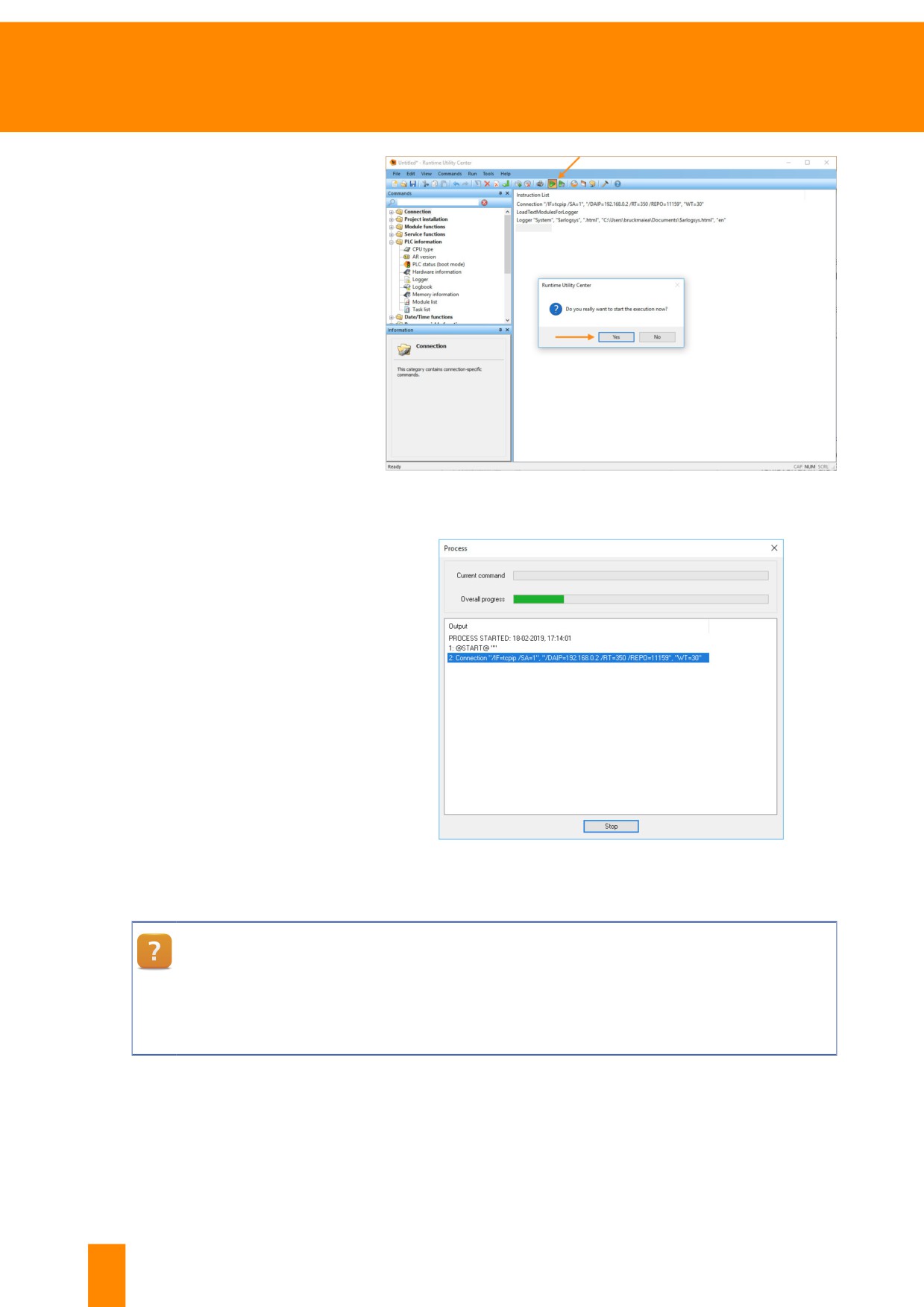
Execute Instruction List
The Instruction List can now be ex-
ecuted. This is done by clicking on
the "Execute" icon in the menu bar
or by pressing the "F5" key. A con-
firmation window appears before
the Instruction List is executed.
Figure 114: Execute Instruction List
A progress indicator appears after
the sequence has been started. As
they are executed, the commands
appear with their status in the out-
put window. The sequence can be
aborted at any time by clicking on
"Stop".
Figure 115: Display of progress indicator for executing Instruction List
Runtime Utility Center \ Operation \ Workspace
Runtime Utility Center \ Operation \ Commands \ Establish connection, wait for new connection
Runtime Utility Center \ Operation \ Commands \ PLC info
Runtime Utility Center \ Operation \ Menus \ Start
80
TM920 - Diagnostics and service
Backing up and restoring
Exercise: Read Automation Runtime version and save Logger file
The Automation Runtime version provides information about the integrated functions of the controller.
The diagnostic data that can be provided depends on the Automation Runtime version, among other
things. Information on events on the controller is recorded in several Logger files. This information helps
to localize sources of errors. Read the installed Automation Runtime version and upload Logger file "$ar-
logsys" from the controller.
1) Start Runtime Utility Center
2) Click on menu option "Create, edit and execute projects (.pil)"
3) Add command "Connection" to Instruction List
4) Add command "AR Version" to Instruction List
5) Add command "Logger" together with Logger file "$arlogsys" to Instruction List
6) Start Instruction List
Exercise: Save profiler file using the Runtime Utility Center
If an error occurs, such as a cycle time violation, then the controller restarts in service mode. Information
about the causative task class is saved in the Logger file. The profiler file contains additional details on
the error. Every newly created profiler file receives a new name. The names of the profiler files end with
the string "$f" and can be identified by uploading a module list.
1) Start Runtime Utility Center
2) Click on menu option "Create, edit and execute projects (.pil)"
3) Add command "Connection" to Instruction List
4) Add command "module list" to Instruction List
5) Start Instruction List
6) Evaluate the names of the profiler files from the module list
7) Add command "Upload" to Instruction List and add the name of the desired profiler file
8) Start Instruction List
Exercise: Backing up all process variables
Perform a data backup by saving all of the variables on a control CPU to a file. The backup can contain
parameters, current process values or settings. The values can only be interpreted in combination with
the control project or through knowledge of the machine manufacturer.
1) Start Runtime Utility Center
2) Click on menu option "Create, edit and execute projects (.pil)"
3) Add command "Connection" to Instruction List
TM920 - Diagnostics and service
81
Backing up and restoring
4) Add command "Variable List" to Instruction List
5) Start Instruction List
Runtime Utility Center \ Operation \ Menus \ File
Runtime Utility Center \ Operation \ Commands \ Establish connection, wait for new connection
Runtime Utility Center \ Operation \ Commands \ List functions
Runtime Utility Center \ Operation \ Menus
After saving all variables from the controller, a file with all variable names and corresponding
values is created. This file can be used at a later point in time for restoring the process data.
This is done by using the process variable function, "Write variable list to PLC".
8.2 Access to the integrated FTP server
B&R control systems have an integrated FTP28 server. If the FTP server is enabled, then the Flash
memory of the controller can be accessed. In order to do this, the configured access rights must allow it
and the username and password must be known. Username and password cannot be reset or changed.
The access data for the FTP server can be found in the corresponding documentation of the machine
manufacturer
For example, configuration files and recipe files can be backed up and restored via this mechanism.
FTP can be accessed, for example, via the Windows command line with the command "ftp ip-adresse",
Internet Explorer or third-party tools (e.g. FileZilla).
28 File Transfer Protocol (FTP) is a network protocol (specified in the RFC 959 from 1985) for transferring data
via IP networks. Source: de.wikipedia.org
82
TM920 - Diagnostics and service

Summary
9 Summary
First an attempt is made to create an overview for a comprehensive diagnosis. The resulting error de-
scription helps with narrowing down to the error source.
A wide range of influences from the surroundings, the raw materials used and process parameters can
affect how a machine works.
B&R products enable complete diagnostics via LED status indicators, System Diagnostics Manager and
Runtime Utility Center. Complete data sheets and wide-ranging user manuals document the technical
data, the installation and the maintenance of all B&R modules.
Figure 116: Examine surroundings
Figure 118: Correct errors
Figure 117: Contact manufacturer
The B&R system overview showed the basic structure of the B&R control system. The diagnostics pos-
sibilities that are available both with and without a PC were also discussed.
A complete overview of the user's manuals for the individual B&R product groups was provided. A check-
list was also introduced to help prepare yourself before contacting B&R.
TM920 - Diagnostics and service
83
Appendix
10 Appendix
10.1 Online connection cable
Ethernet connection cable
A standard crossover network cable is recommended when connecting the B&R controller to a PC.
Serial connection cable
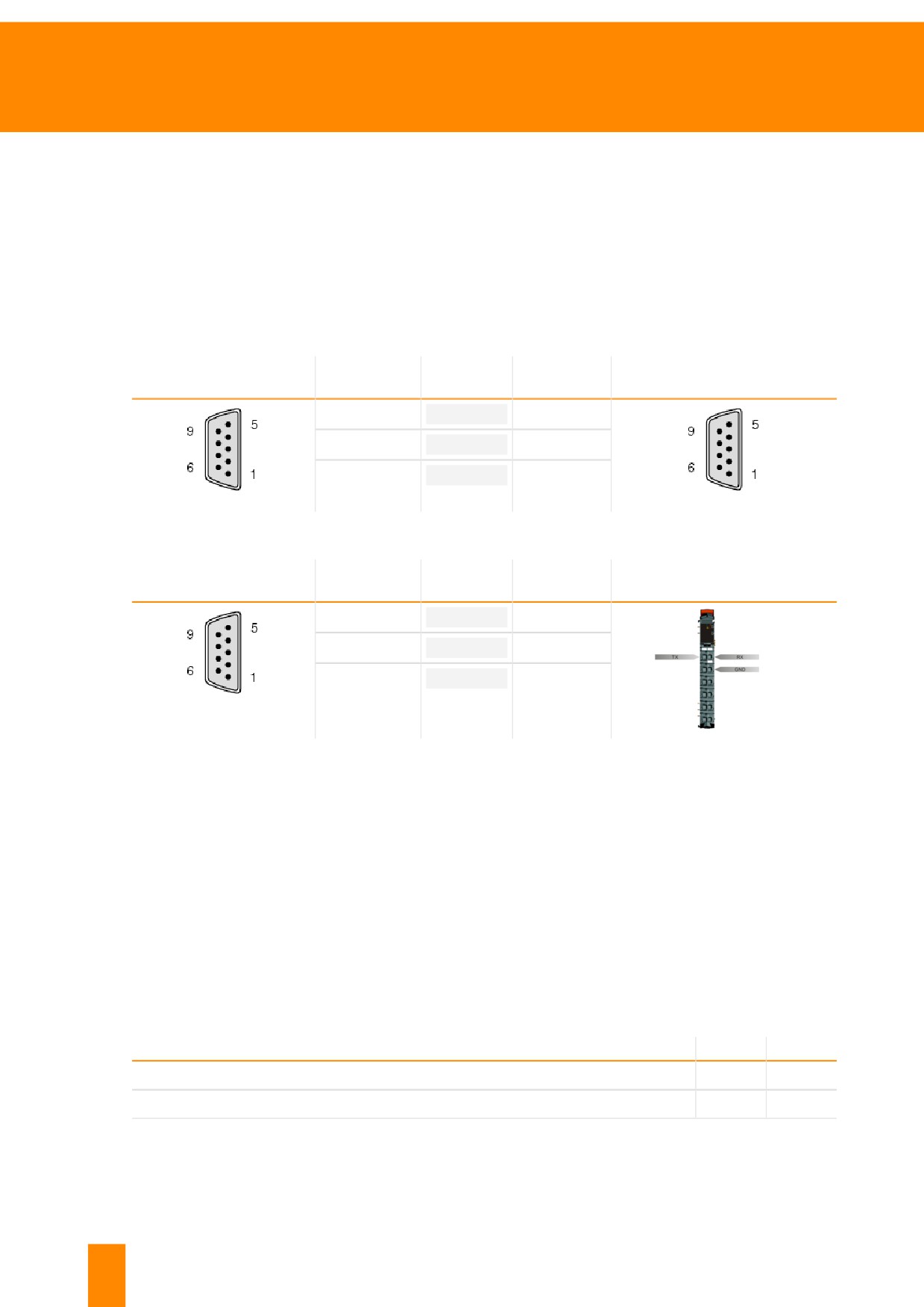
A cable with the following pinout is required to connect a B&R controller to a PC via the serial interface.
9-pin female DSUB
9-pin female DSUB connec-
PC
Control
connector
tor
2 (RXD)
-----
3 (TXD)
3 (TXD)
-----
2 (RXD)
5 (GND)
-----
5 (GND)
Table 9: Cable pinout for online connection cable
9-pin female DSUB
PC
Control
X20 controller terminal block
connector
2 (RXD)
-----
11 (TXD)
3 (TXD)
-----
21 (RXD)
5 (GND)
-----
22 (GND)
Table 10: Cable pinout for direct connection to an X20 terminal block
10.2 Where SDM and Runtime Utility Center can be used
The following tables compare the possibilities of the System Diagnostics Manager (SDM) and the Run-
time Utility Center (RUC).
In general, the SDM can only be used if a system has an integrated web server and it is enabled. Read
access is granted on the controller. No additional software installation is necessary on the PC.
The Runtime Utility Center can be used to diagnose systems without integrated web server and to back
up and restore data. A serial or Ethernet port can be used for connection. The Runtime Utility Center
must be installed on a PC with a Windows operating system before use.
General diagnostics
Function
SDM
RUC
Output and set time
Yes29
Yes
Output battery status
Yes
No
Table 11: Comparison of general diagnostics functions
29 Time can only be output in SDM.
84
TM920 - Diagnostics and service

Appendix
Function
SDM
RUC
Output system version
Yes
Yes30
Read Logger31
Yes
Yes
Output hardware list
Yes
Yes
Detect hardware problems
Yes
No
I/O and read status data points
Yes
No
Determine system usage
Yes
No
Output memory usage
Yes
Yes
Output configured timing
Yes
No
Output module lists
Yes
Yes
Output axis errors
Yes
No
Reading network command trace
Yes
No
Install trace configuration32
Yes
No
Table 11: Comparison of general diagnostics functions
Backing up and restoring
Function
SDM
RUC
Saving Logger files
Yes
Yes
Saving profiler files
Yes
Yes33
Generate system dump
Yes
No
Upload software objects
No
Yes
Download software objects
No
Yes
Backing up and restoring a CompactFlash card
No
Yes
Back up and restore variables
No
Yes
Output and display variables
No
Yes
Table 12: Comparison of back up and restore options
30 The runtime environment has software versions for the operating system, motion control and visualiza-
tion.In the Runtime Utility Center, only the operating system version can be output.
31 There are usually several Logger files on current B&R control systems for diagnosing different functional
areas of the controller. For control systems that do not have a USB interface or an onboard Ethernet inter-
face, function "Logbook" of the Runtime Utility Center must be used.
32 Installing a trace configuration makes it possible to record pre-configured process values on the runtime
system.The finished recording can then be uploaded from the controller for further analysis.
33 The profiler file can be loaded via the "Upload" module function on the controller. The name of the profiler
file ends with the string "$f" and can be identified by uploading a module list.
TM920 - Diagnostics and service
85
Appendix
10.3 Changing network settings on the PC
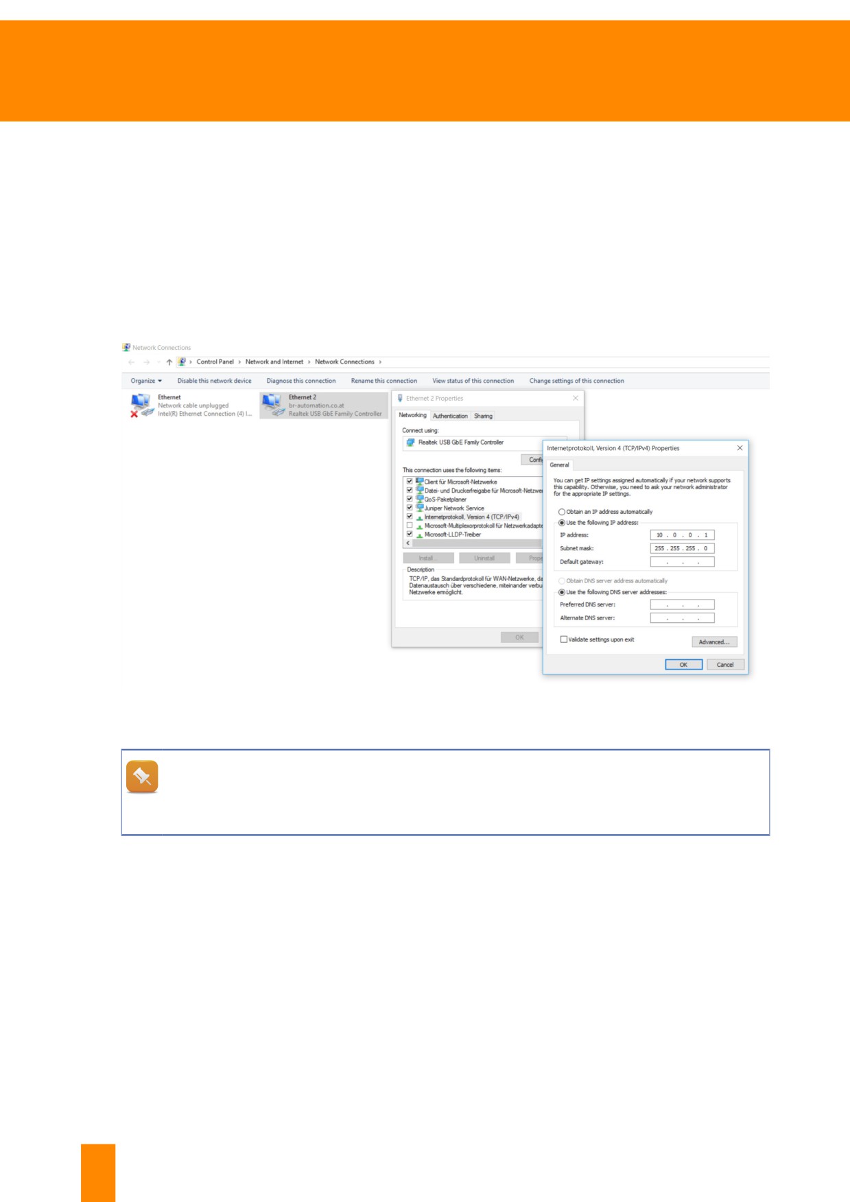
The IP address of the Ethernet interface can be changed on the PC. This is done via the settings of
the network adapter, see Windows 10 "Control Panel" \ "Network and Internet" \ "Network and Sharing
Center" \ "Change adapter settings". All available network connections are displayed.
Right-click on the desired adapter, then click on "Properties". Select "Internet Protocol, version 4 (TCP/
IPv4)" and click on "Properties". Now the IP address can be changed.
As shown in the example, a static IP address with value "10.0.0.1" and subnet mask "255.255.255.0"
are assumed for the controller. The configuration of the PC must be in the same subnet.
Figure 119: Windows 10: Change adapter settings for the LAN Connection adapter under Network and Sharing Center.
We recommend writing down the original adapter settings before making any changes.
By entering "Show network connections" in the search field of the Windows 10 Start menu, the
selection is already restricted making it possible to get the list of network adapters more quickly.
86
TM920 - Diagnostics and service
Appendix
10.4 Notes regarding grounding and shielding
The following section compiles a few universally applicable recommendations for grounding and shield-
ing. The regulations in the respective user's manual always apply. The procedure for correcting prob-
lems on machines where grounding and shielding result in failures should be adapted on a case-by-
case basis.
Shielding and grounding for control systems
On all shielded cables, the shield must be grounded. These
include:
• Analog signals (input and output modules)
• Interface modules
• Counter modules
• X2X Link cables
• Fieldbus connections (POWERLINK, PROFIBUS DP, CAN,
etc.)
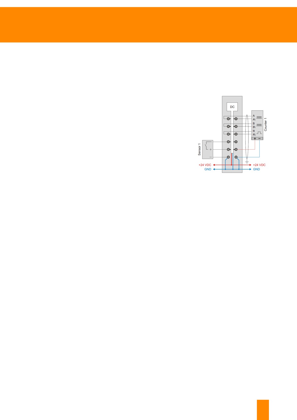
Figure 120: X20DC1176 connection
schematic - Encoder cable connection
with shielding
The following general guidelines apply for shielding:
• The top-hat rail must always be mounted to a conductive backplane.
• The control cabinet back wall must be connected with GND.
• Shielded cables must be grounded on both sides.
TM920 - Diagnostics and service
87
Appendix
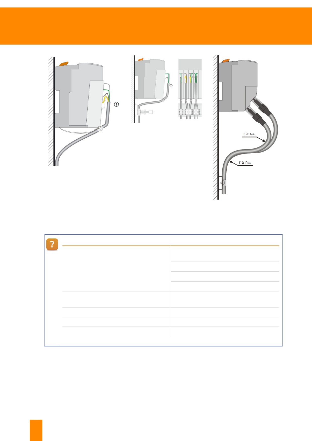
Figure 122: Shielding via top-hat rail
or busbar
Figure 121: Shielding via X20 cable
shield clamp
Figure 123: Wiring diagram for X20
modules with an Ethernet cable
"X20 system user's manual"
Content
Chapter 4 "Mechanical and electrical config-
Direct connection of the shield to the ground
uration"
connection of bus modules
Cable shielding plate
Chapter 4.6
Shielding bracket
Shielding via top-hat rail or busbar
Chapter 4.7
Wiring guidelines for X20 modules with an
Ethernet cable
Chapter 7.10.2
General specifications for X2X Link cables
Chapter 8.2.2
Requirements for immunity to disturbances
Chapter 8.2.3
Emission requirements
Table 13: Notes regarding shielding and grounding in the control system
88
TM920 - Diagnostics and service
Appendix
Installation / EMC guide
Content
Chapter 3.3.3 "Installation with increased vi-
Padding, retaining clips, adjustment, cover-
bration requirements (4 g)"
ing unused slots, strain relief
Chapter 3.4.1.2 "Shield connection"
Ground connection, shield terminal blocks,
bend radius
Chapter 6.3 "Buffer module"
24 V power supply buffering
Table 14: Installation notes for control systems
Shielding and grounding for drive technology
• To prevent the effects of disturbances, the following cables must be properly shielded:
° Motor cables
° Encoder cables
° Control cables
° Data cables
• Inductive switching elements such as contactors or relays must be equipped with correspond-
ing suppressor elements such as varistors, RC elements or damping diodes.
• All electrical connections must be kept as short as possible.
• Cable shields must always be attached to the designated conductive shielding clamps and the
connector housing. Twisting the braided shield or extending it with individual conductors is not
permitted!
• Shielded cables with copper braiding or tinned copper braiding must be used.
• Unused cable conductors must be grounded on both sides whenever possible.
"ACOPOSmulti user's manual", chapter 5 "Wiring":
• Subsection 1.1 "EMC-compliant installation"
• Subsection 1.1.4 "Connection diagrams for ground connections and shield connec-
tions"
Exercise: Check the installation with regard to electromagnetic compatibility (EMC)
Downtime caused by EMC problems can be prevented by installing appropriate components. Corre-
sponding recommendations are provided in the data sheets and user's manuals. B&R components are
designed for complete shielding and grounding. This includes shield component sets available as acces-
sories for control and I/O systems, for example. B&R recommends connecting controllers and remote I/
O systems to the cables offered in the B&R product catalog. Detailed specifications for cables used in an
industrial environment are available in the respective data sheet.
1) Look up the shielding and grounding concepts for X20 modules in the X20 system user's manual
2) Cable shield for X20 modules - Shield component set
3) Look up the specifications for X2X and POWERLINK cables
TM920 - Diagnostics and service
89
Appendix
User's manual "X20 System user's manual":
• Chapter 4.6 "Shielding"
• Chapter 4.7 "Cabling guidelines for X20 modules with Ethernet cables"
• Chapter 7.3 "Cable shield plates"
User's manual "Installation / EMC guide"
Data sheet "POWERLINK cable X20CA0E61.xxxx", search within data sheet for
"X20CA0E61.00020"
Data sheet "Data sheet X2X Link Cable (X67CA0Xxx)", search within data sheet for
"X67CA0X99.1000"
90
TM920 - Diagnostics and service
Appendix
10.5 Power supply and fuses
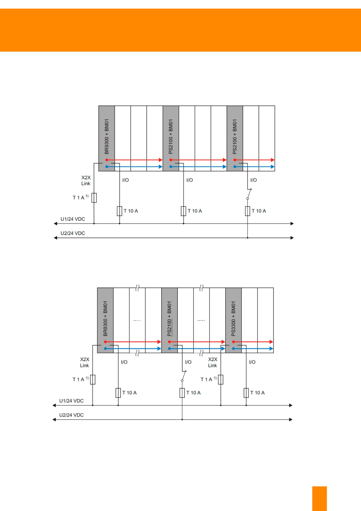
The protection for the X20 system depends on the supply concept. Using the X20BM01 bus module and
organizing the power supply bus modules accordingly allows various potential groups to be implemented
(e.g. for input groups or various power circuits for the outputs).1)
Figure 124: Protecting various potential groups
It is possible to set up potential groups through the use of different supplies for the power supply modules.
Figure 125: Example of extended X2X Link power supply
1) A 1 A slow-blow fuse is recommended for the bus supply.
TM920 - Diagnostics and service
91
Appendix
"X20 system user's manual"
• Chapter 4.8 "Power supply concept"
• Chapter 4.9 "Fuse protection of the X20 system"
• Chapter 4.9.1 "Potential groups"
• Chapter 4.9.2 "Supply via bus transmitter"
• Chapter 4.8.12 "X2X Link supply"
• Chapter 4.8.12.1/2 "Extended and redundant X2X Link supply"
92
TM920 - Diagnostics and service
Offered by the Automation Academy
Offered by the Automation Academy
Die Automation Academy ist für die zielgerichtete Weiterbildung unserer Kunden und eigenen Mitarbeiter
verantwortlich.
Mit der Automation Academy erreichen Sie Handlungskompetenz in kurzer Zeit!
Unsere Seminare ermöglichen Ihnen, Ihre Kompetenz auf dem Gebiet der Automatisierungstechnik zu
erweitern.
Sie werden danach in der Lage sein, selbständig effiziente Automatisierungslösungen mit B&R Sys-
temen zu realisieren. Sichern Sie sich entscheidende Wettbewerbsvorteile, um auf die ständig wach-
senden Anforderungen des Marktes schneller reagieren zu können.
Seminars
Qualität und Aktualität sind bei Seminaren unverzichtbar. Das Lerntem-
po im Seminar wird durch das Vorwissen der Teilnehmer und deren An-
forderungen bestimmt. Unsere Seminare bieten hohe Flexibilität beim
Aufbau des Wissens durch die ideale Kombination von Gruppenarbeit
und individuellem Lernen.
Die effizienten Seminarblöcke werden von didaktisch und fachlich
bestens ausgebildeten Technikern geleitet.
Training modules
Topic categories:
Die Basis für das Arbeiten im Seminar und beim Selbststudium
➯ Control technology
bilden unsere Trainingsmodule. Die kompakten Module basieren auf
➯ Motion control
einem einheitlichen didaktischen Konzept. Strukturierte und aufeinan-
➯ Safety technology
der aufbauende Inhalte erleichtern das Verständnis für komplexe
➯ HMI
Zusammenhänge. Sie stellen das ideale Begleitmaterial zum umfan-
➯ Process control
greichen Hilfesystem dar. Die Trainingsmodule sind als Download
verfügbar und sind als Druckversion bestellbar.
➯ Diagnostics and service
➯ Connectivity
ETA system
The ETA system provides realistic assemblies for training, education and
laboratory use. Two different basic mechanical systems can be selected.
The ETA light system offers a high degree of mobility, saves space and
is well-suited for lab work. The ETA standard system has a sturdy me-
chanical structure and includes pre-wired sensors and actuators.
Find out more!
Would you like additional training? Are you interested in finding out what the B&R
Automation Academy has to offer? You've come to the right place.
Detailed information can be found under the following link:
TM920 - Diagnostics and service
93