TM920 Diagnostics and service (2018) - page 1
Prerequisites and requirements
Basic technical training
General
Access to www.br-automation.com.
Automation Runtime 4.33
Software
Windows 10
X20 system user's manual - Version 3.50 (October 2018)
Installation / EMC guide - Version 1.20 (June 2018)
ACOPOSmulti user's manual - Version 1.10 (April 2018)
Documentation
Redundancy for control systems - Version 1.14 (September 2017)
ACOPOSinverter P74 user's manual - Version 2.60 (December 2018)
Integrated Safety Technology user's manual - Version 1.120 (July 2017)
SafeMOTION user's manual - Version 4.5 (November 2018)
2
TM920 - Diagnostics and service
Table of contents
Table of contents
1 Introduction
5
1.1 Learning objectives
5
1.2 Safety notices and symbols
6
1.3 Terminology
7
2 Situation analysis and problem identification
9
2.1 Checking possible sources of error
9
2.2 Source of information: Machine manufacturer
12
2.3 Source of information: B&R
13
3 System overview and topologies
15
3.1 B&R system overview
15
3.2 Typical topologies
16
4 Obtaining information about the B&R system
20
4.1 Serial numbers and model numbers
20
4.2 Data sheets and user's manuals
23
4.3 Structure of B&R user's manuals
23
4.4 B&R website functions
24
5 Diagnostic tools
32
5.1 Diagnostics without a PC
32
5.2 Diagnostics via PC
36
6 Diagnostics using the System Diagnostics Manager
39
6.1 SDM functions
40
6.2 Establishing a connection to the SDM
44
6.3 Saving Logger files
45
6.4 Generating and saving a system dump
47
6.5 Information in the hardware tree
48
6.6 Diagnostics via I/O and status data points
52
6.7 Information about the application status in WebXs
54
7 Troubleshooting
56
7.1 Service parts
56
7.2 Replacing a module
57
7.3 Starting up again and functional testing
68
8 Backing up and restoring
70
8.1 Backing up and restoring using the Runtime Utility Center
70
8.2 Access to the integrated FTP server
82
9 Summary
83
10 Appendix
84
10.1 Online connection cable
84
10.2 Where SDM and Runtime Utility Center can be used
84
10.3 Changing network settings on the PC
86
TM920 - Diagnostics and service
3
Table of contents
10.4 Notes regarding grounding and shielding
87
10.5 Power supply and fuses
91
4
TM920 - Diagnostics and service

Introduction
1 Introduction
For decades, the company B&R Industrial Automation GmbH1 has been a leader in innovation and full-
line supplier of control technology in the field of mechanical engineering.
Our customers are machine and system manufacturers who use B&R products for automation. The
machine and system manufacturers are generally responsible for software programming, maintenance,
spare parts supply and warranty claims.
Figure 1: Examine surroundings
Figure 3: Correct errors
Figure 2: Contact manufacturer
The B&R website offers all of the documentation and user's manuals for our products as well as a
complete product overview.
Further information
•
4.4 "B&R website functions" on page 24
1.1 Learning objectives
This training module provides an overview of the B&R system and corresponding documentation re-
sources. It also provides an overview of available diagnostic options. Many exercises and application
examples included serve to expand upon the lessons learned.
• Participants will learn about B&R's approach to integrated automation and where to find neces-
sary sources of information.
• Participants will learn their way around the B&R website and find out how to download user's
manuals and data sheets.
• Participants will be familiar with the diagnostic options that are available without using a PC.
• Participants will learn how to perform basic diagnostics without a PC and how to interpret the
resulting data using the available data sheets and user's manuals.
• Participants will learn about the diagnostic options that do require a PC and how to evaluate
the information they provide.
• Participants will learn how to replace modules and resume operation of the B&R system.
• Participants will learn whom to contact in order to obtain specific information.
• Participants will know the possibilities for backing up and restoring data
• Participants will learn how to backup and restore the values of process variables on a B&R
controller.
1
TM920 - Diagnostics and service
5

Introduction
1.2 Safety notices and symbols
Safety notices in this manual are organized as follows:
Danger: Disregarding these safety guidelines and notices can result in severe injury, death or
substantial damage to property.
Warning: Disregarding these safety guidelines and notices can result in severe injury or sub-
stantial damage to property.
Caution: Disregarding these safety guidelines and notices can result in injury or damage to
property. These instructions are important for avoiding malfunctions.
Additional notices and information in this manual are organized as follows:
Note: Provides important tips and additional information
Help: References additional documentation (Automation Help, data sheets, user's manuals)
Example:
Hardware \ Motion control \ <Device>2 \ Technical data \ (<Type>)3 \ Status indicators
Example: An example illustrates the topic in greater depth.
Result: The result of a completed exercise is summarized briefly.
Organization of safety notices in external manuals
This manual contains references to other manuals. How safety notices are organized in external manuals
is listed in the respective manual.
Exercise: Tasks and exercises
Sections marked with an orange stripe on the left side contain information about exercises as well as
the associated actions to be taken. The exercises are designed to provide a deeper understanding of
the information provided.
2
Angle brackets indicate variable placeholders "<...>"
3
Parentheses indicate optional entries "(...)"
6
TM920 - Diagnostics and service

Introduction
1.3 Terminology
Below is a glossary of the most important terminology used in B&R systems. The
definitions are of particular importance because these terms are used frequently
throughout this documentation as well as in the respective user's manuals.
Term
Short description
ACOPOS
General name for B&R drives. These power electronics are controlled via a field-
bus connection and used to control the movement of all types of motors.
Motion control
Umbrella term for anything involving movement. Power electronics controls the
movement of drive systems, such as synchronous, induction and stepper mo-
tors.
Automation
Automation Runtime is the operating system installed on the controller. Different
Runtime
versions of Automation Runtime installed on the controller offer different func-
tions and diagnostics options.
APC / IPC
Automation PC or industrial PC: PC designed for industrial use.
CF
CompactFlash is the external memory of the controller. Almost all B&R control
systems use a CompactFlash card as an application memory. Other systems
that do not use CompactFlash cards have the application memory integrated in
the controller, and it cannot be replaced externally. Using CompactFlash cards
provided by B&R ensures image compatibility and suitability for industrial envi-
ronments.
Remote I/O
Instead of being connected directly to the CPU, remote I/O modules can be op-
erated remotely via a fieldbus system.
Node number
The node number is set on the module via rotary switches. This number is re-
quired to identify the module in the network.
Panel
HMI devices are often described as operator panels or simply panels.
POWERLINK
Open, Ethernet-based fieldbus for connecting controllers, drives, safety technol-
ogy and remote I/O modules.
Safety
General term for safety technology in the field of machine manufacturing. The
safety components process safe input and output data, such as emergency
switch-off, enable signals, safety doors and much more.
System 2000
General term referring to B&R's 2003, 2005 and 2010 control systems.
Technology Guard
This is a USB dongle that is inserted in the controller CPU's USB port. The
Technology Guard contains any required software licenses, two operating hours
counters and permanent data storage.
Visualization
Umbrella term for displaying processes and process values. An HMI device (e.g.
with touch screen) can be used to interact with the visualized machine functions.
X2X Link
Connects controller CPUs to X20 or X67 components. Serves as a remote back-
plane for transferring I/O data to the bus controller or CPU.
X20
Components with IP20 protection4. Complete control system with CPUs, remote
I/O modules and broad fieldbus support.
Table 1: Terminology
4
IP20 = Protection against ingress of solid foreign bodies >12.5 mm and no protection against ingress of
water. Source: IEC/EN 60529
TM920 - Diagnostics and service
7
Introduction
Term
Short description
X67
Components with IP67 protection5. B&R's remote I/O system.
Table 1: Terminology
5
IP67 = Protection against dust and temporary immersion in water
8
TM920 - Diagnostics and service

Situation analysis and problem identification
2 Situation analysis and problem identification
Before contacting the manufacturer of the control electronics or the
machine manufacturer, it is necessary to get an overview of the sys-
tem to isolate and localize the problem. Working one step at a time
and documenting each step along the way is the most productive
approach.
It is often external influences that occur with daily use of the ma-
chine that cause the smaller problems. The following contents help
to identify problems and analyze the current situation.
If the problem is recognized correctly, it is easier to initiate the next steps. In addition, the time required
to solve the problem can be significantly reduced.
2.1 Checking possible sources of error
Acquiring as much information as possible for a clear overview is the first line of action.
The general conditions under which the machine is operated are crucial factors as is the timing of actions
performed by the machine operator.
"Has anything been changed on the machine? Were the actions taken also documented?"
This information helps to isolate the cause of error step by step and helps develop a solution.
2.1.1 Operating materials
Operating materials are crucial to the lifespan of a machine. Neglecting these materials can lead to
machine downtime or have negative effects on functionality.
Operating materials include:
• Lubricant
• Compressed air
• Hydraulic fluid
• Coolant
• Electricity
2.1.2 Mechanics
The mechanics in a machine are often subject to demanding conditions. Years of operation will eventually
lead to wear and tear.
Typical problems
• Worn bearings6
• Poor lubrication
• Warping
• Increased play (worn toothed gears, gear backlash)
• Belt tension on the drives not as specified by the manufacturer
• Damage caused by jolts and vibrations
6
The ability to predict machine and system failures before they happen reduces costs and increases avail-
ability.Condition monitoring modules from B&R precisely detect potential cases when service work may be
needed.
TM920 - Diagnostics and service
9

Situation analysis and problem identification
2.1.3 Power supply, supply network
First the electricity supply makes machine operation possible. A stable supply network is a requirement
for permanent and reliable machine operation.
Potential problems with the supply:
• Voltage fluctuations
• powerfail message
• Phase failure
• Defective or weak fuse
• Differences in potential
• Uneven network load
2.1.4 Wiring, cabling, shielding
Sensors and actuators are connected to the I/O system through wiring. Likewise, all remote control
components, such as the controller itself, are connected with higher-level fieldbuses or networks.
Potential wiring problems:
• Open lines
• Poor contact
• Unplugged connector
• Unsuitable cable
• Bus, sensor and motor cables with poor or no shielding7
• Poor or worn insulation
• Short circuits and cross faults
• Ground fault
• Insufficient flex radius
• Coupling of disturbances caused by inappropriate shielding
• Excessive cable lengths (voltage drop and reflections)
• Missing terminating resistors during network coupling (e.g.
CAN Bus)
Where can I find information about wiring, shielding and grounding concepts?
Descriptions regarding wiring, shielding and grounding concepts for the B&R system can be
found in the respective B&R user's manual. Connection examples for individual hardware com-
ponents are also included.
Further information
•
4.3 "Structure of B&R user's manuals" on page 23
7
10.4 "Notes regarding grounding and shielding" on page 87
10
TM920 - Diagnostics and service
Situation analysis and problem identification
2.1.5 Environmental and time factors
In addition to other defects that can occur due to damaged mechanics or wiring, environmental factors
and the effect of time are also causes of errors.
This includes the following influences:
• High and low temperatures, temperature fluctuations (temperature limit values are documented
in the user's manual)
• Heat accumulation from incorrect installation position or from minimum spacing not being ob-
served
• Humidity and condensation, incorrectly configured climate control systems
• Dust and dirt
• Oily or aggressive vapors in the air
• Vibrations
• Aging, material fatigue
• UV radiation
• Derating due to elevation (specification listed in the user's manual)
Where are the limit values listed?
All limit values, such as ambient temperature or humidity, for operating the B&R product can
be found in the respective user's manual.
Further information:
•
4.3 "Structure of B&R user's manuals" on page 23
2.1.6 Process parameters
Modern machines are capable of performing flexible manufacturing processes for a wide range of prod-
ucts. Settings and configurations make it possible to adapt the machine to the production process.
Process-related variables affect the machine's response.
Influences for the machine:
• Changed parameters
• Changed controller settings
• Change in behavior by the machine operator
• New recipe loaded
• Changed limit values
• Different raw material or product
• Different material or temperature
• Higher or lower material hardness
• Other tool properties
2.1.7 Controller electronics
The smooth operation of electronics is guaranteed for certain general conditions. These limits are defined
in standards. The potential sources of error described above may lead to the failure of an electronic
component. It is important to detect any defects so that the necessary measures for maintenance or
replacement can be taken.
TM920 - Diagnostics and service
11
Situation analysis and problem identification
Further information
•
2.2 "Source of information: Machine manufacturer" on page 12
•
5 "Diagnostic tools" on page 32
•
7 "Troubleshooting" on page 56
2.1.8 Software, process
The software on the machine controller represents and controls complex machine processes. Software
errors do not simply appear without reason, but occur mostly when process values have changed and
the corresponding software function has not been adequately tested.
If limit values are exceeded without consideration, this represents a potential source of error.
Potential sources of errors:
• All of the factors described above
• Faulty programming, insufficient software tests
• Limit values are exceeded due to incorrect entries but not regarded in the software
• Combinations of different machine functions were not completely tested
• Program for sequential control doesn't take account of all machine conditions
2.2 Source of information: Machine manufacturer
Required information for machines should be obtained ideally from
the machine manufacturer. The following list provides an overview
of the information that can be requested from the machine manufac-
turer or that can be found directly on the machine.
The following information is available:
• Images on the HMI application
° Overview pages
° Alarm pages
° Diagnostic pages8
° Error logs, log files
° Trend curves
• Manual of the machine
° Machine data
° Error descriptions
° Suggested corrective measures
° Maintenance guidelines
° Lubrication chart of mechanical parts
° Tightening torque for belt tension
° Contact data
• Circuit diagrams of the machine
• Website of the machine manufacturer
8
System Diagnostics Manager is a web-based interface that is used for diagnosing B&R systems. The con-
tents of System Diagnostics Manager can be directly integrated in the HMI application by the machine
manufacturer, see:6 "Diagnostics using the System Diagnostics Manager" on page 39.
12
TM920 - Diagnostics and service

Situation analysis and problem identification
Contact the machine manufacturer
If replacement parts or service is needed, the first point of contact is always the machine manufacturer.
They know the machine's structure, the mechanics, electronics and application software.
Contact data can usually be found in the control cabinet or in the user's manual. Most manufacturers
have their own website that also contains contact data.
When contacting the machine manufacturer, make sure you have the machine number and a
clear description of the problem prepared.
2.3 Source of information: B&R
B&R's systems are completely documented and operated the same way. A broad
range of diagnostics options provide information about the system status and help to
perform initial diagnostics and error localization.
Further information:
•
4 "Obtaining information about the B&R system" on page 20
•
5 "Diagnostic tools" on page 32
Checklist for contacting B&R
In some rare cases, the machine manufacturer may no longer be in business. In this case, be sure to
contact the nearest B&R subsidiary. You can always find contact information for the nearest subsidiary
on the B&R website:
There are a few things to clear up before contacting the manufacturer or B&R. The following checklist
can be used as a guide when preparing to contact B&R.
Question
Notes
Company name, location, contact data
Machine manufacturer?
Packaging machine, pump controller, etc.
Machine type?
Brief description of the production process
What is being produced?
What type of problem is
Description of the type of problem: Standstill, noises, product quali-
occurring?
ty, communication failure, etc.
How often does the prob-
Approximate frequency of problem:
lem occur?
Once a day, every hour, just once, etc.
When did the problem
Started: "... last Wednesday at ..."
first occur?
Is the behavior repetitive? Under what conditions does the behavior
Reproducibility
occur?
Table 2: Checklist for B&R contact
TM920 - Diagnostics and service
13

Situation analysis and problem identification
Question
Notes
Under what environmental conditions (temperature, humidity, etc.)
Environmental conditions
is the machine being operated. Installation of electromagnetic com-
patibility (EMC)
Different product being produced, mechanical modifications,
Has anything been
changes to cabling, software update from the manufacturer,
changed?
changed parameters, etc.
Contact person, documentation of the changes, reasons for
Who made the changes?
changes, etc.
What controller is being
Hardware being used, control concept, etc.
used?
What fieldbus is being
How the components and modules are connected together, etc.
used?
Have a topology diagram ready, state the important components,
etc.
What does the topology
Further information:
look like?
•
3.2 "Typical topologies" on page 16
What states are being signalized by the LED status indicators?
LED status indicators
(Controller, I/O modules, interfaces, bus controller, drives, etc.)
Who is responsible for the
Control program for the machine controller, source control system,
software?
archiving
Are there any backups?
Generate system dump according to the instructions and have it
ready. All hardware modules and software versions used as well as
Logger and profiler files are saved in the system dump.
System dump
Further information:
•
6.4 "Generating and saving a system dump" on page 47
Every B&R module has a serial number. The serial number provides
important data and information.
Which parts of the machine and which hardware is affected?
serial numbers
Further information:
•
4.1 "Serial numbers and model numbers" on page 20
Table 2: Checklist for B&R contact
Exercise: Preparing the B&R checklist
In this exercise you will draw up a brief list to determine whether all of the relevant data is available for
an existing machine. If you're already certain that some important information is missing or cannot be
determined, efforts can be made to obtain this information.
1) Go through the checklist for a machine one step at a time
2) Write down information that is already known
3) Note down the information that must be obtained later
4) Clarify whether the offered service and diagnostics methods are supported
14
TM920 - Diagnostics and service

System overview and topologies
3 System overview and topologies
3.1 B&R system overview
B&R offers products for every aspect of a machine's electronics. Controllers, HMI units, I/O modules,
motion control technology and a variety of infrastructure components such as cables, power supplies
and network components make up the B&R product portfolio.
B&R products are divided into the following main categories:
• Control technology
• Motion control
• Safety technology
• HMI
B&R product overview
The following image provides an overview of the main B&R product groups. On the left you see some
motion control components. Control technology, remote I/O modules and integrated safety technology
are shown front and center. In the back and on the right you see an operator panels and industrial PC.
Figure 4: B&R product overview (from left to right: synchronous motor, ACOPOSmulti system, X20 system and integrated safety
technology (yellow), Automation Panel, Power Panel, Automation PC)
Where can I find detailed product information?
For a detailed overview and description of the individual product groups, refer to the B&R web-
The entire product catalog can be downloaded in section "Downloads" selecting "Catalogs and
Brochures" / "Products" / "Product Catalog" in the respective drop-down menu.
Further information:
•
4.4 "B&R website functions" on page 24
TM920 - Diagnostics and service
15
System overview and topologies
3.2 Typical topologies
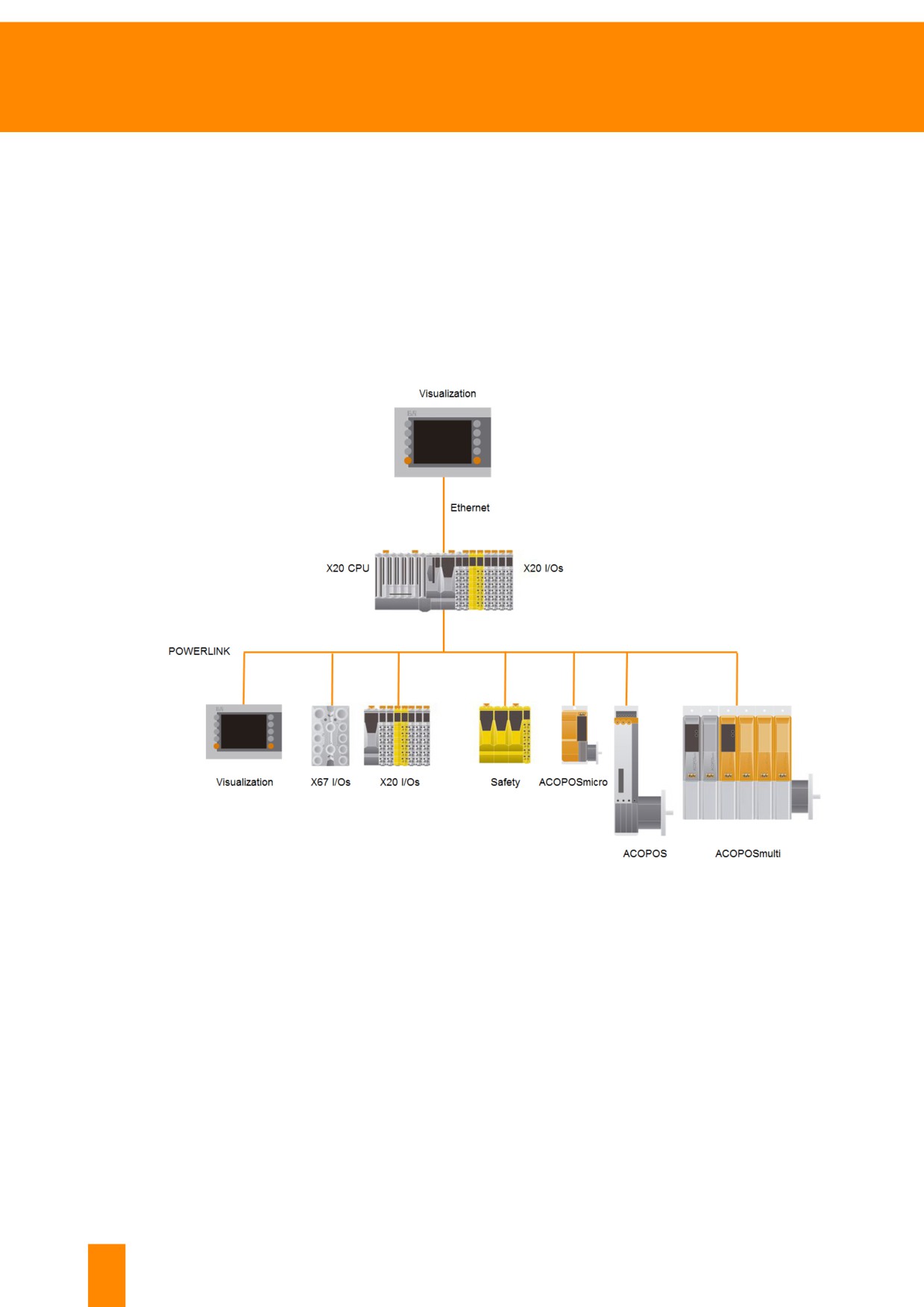
If the problem can be solved by replacing a module, the existing topology must be examined first. The
following image shows a typical control topology as those found on many other machines.
In the center you see the machine controller. It is connected to the other control components via a
fieldbus, most commonly POWERLINK. This is what allows the machine controller to control the remote
components.
An X20 CPU, an HMI device or an industrial PC can be used as the machine controller. Above this, HMI
devices or other network components can also be connected via a network connection.
Figure 5: Typical control topology with an X20 CPU
16
TM920 - Diagnostics and service
System overview and topologies
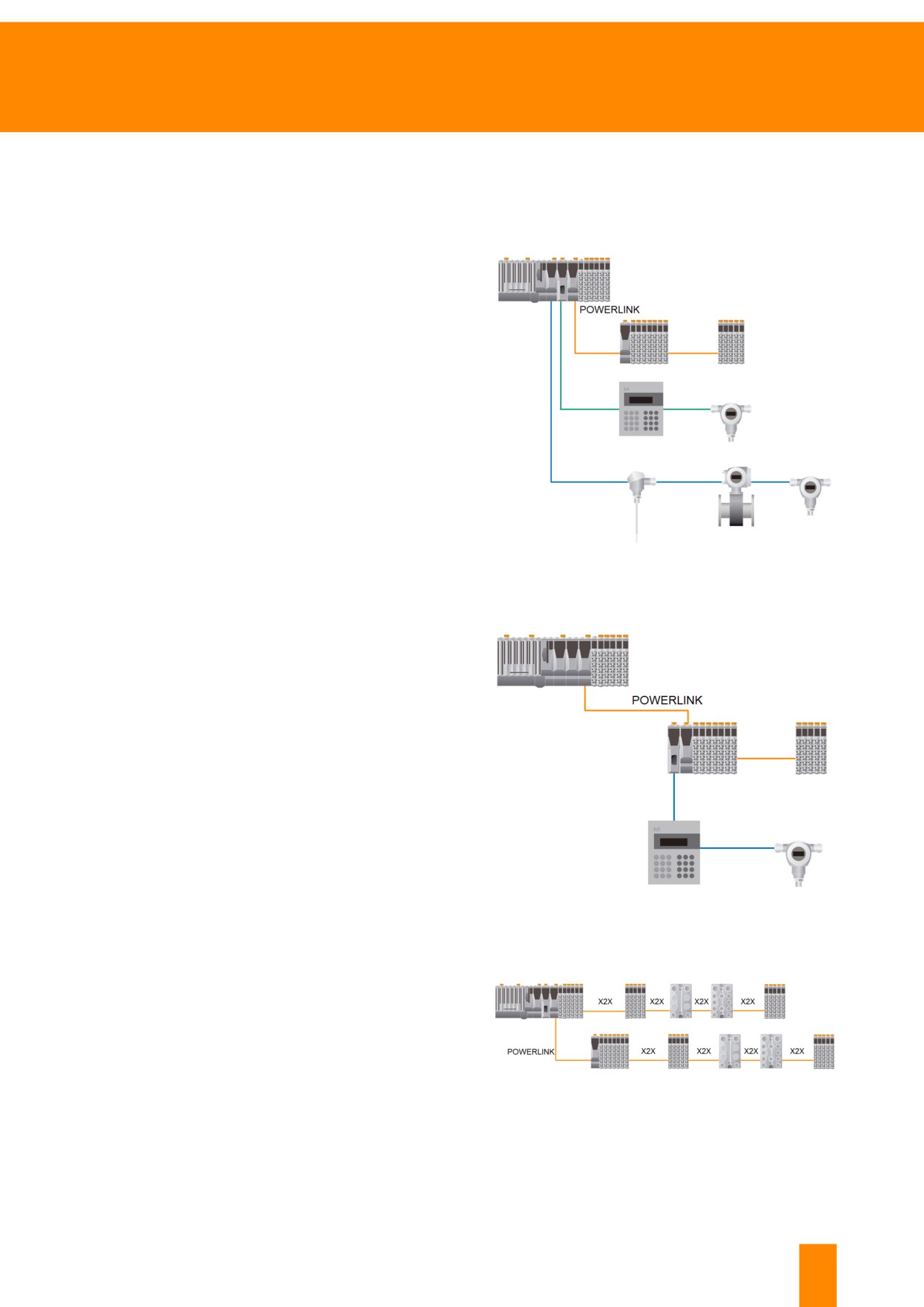
3.2.1 Expansion via fieldbus
Communication with 3rd-party devices via different fieldbus systems is a basic feature of B&R systems.
The fieldbus that is used to connect a device can be connected to various positions in the system.
Fieldbus connection to the control CPU
All B&R control systems offer additional slots for
fieldbus interfaces, which allows them to be ex-
panded easily at any time without having to add
new interfaces. A wide range of fieldbus interfaces9
are available for connecting different devices.
Figure 6: Connection of X20 I/Os via POWERLINK in addition
to two other fieldbuses (blue and green)
Fieldbus connection to POWERLINK
An expandable bus controller allows B&R to also
offer fieldbuses right at the level of the I/O system.
The additional fieldbus interface is connected right
next to a POWERLINK bus controller. This makes
it possible to add a fieldbus interface anywhere on
the machine.
Figure 7: Additional fieldbus interface next to the
POWERLINK bus controller
Remote backplane - X2X Link
Multiple I/O stations consisting of X20 and X67
modules can be connected via X2X Link.
The maximum distance between two modules is
100 meters. Up to 254 modules are supported per
line.
Figure 8: X20 and X67 modules can be connected to the CPU
via X2X Link or POWERLINK. X20 and X67 modules are
linked together using X2X Link.
9
A few examples of fieldbus systems include: POWERLINK, Profibus, DeviceNet, etc.
TM920 - Diagnostics and service
17
System overview and topologies
3.2.2 Redundancy
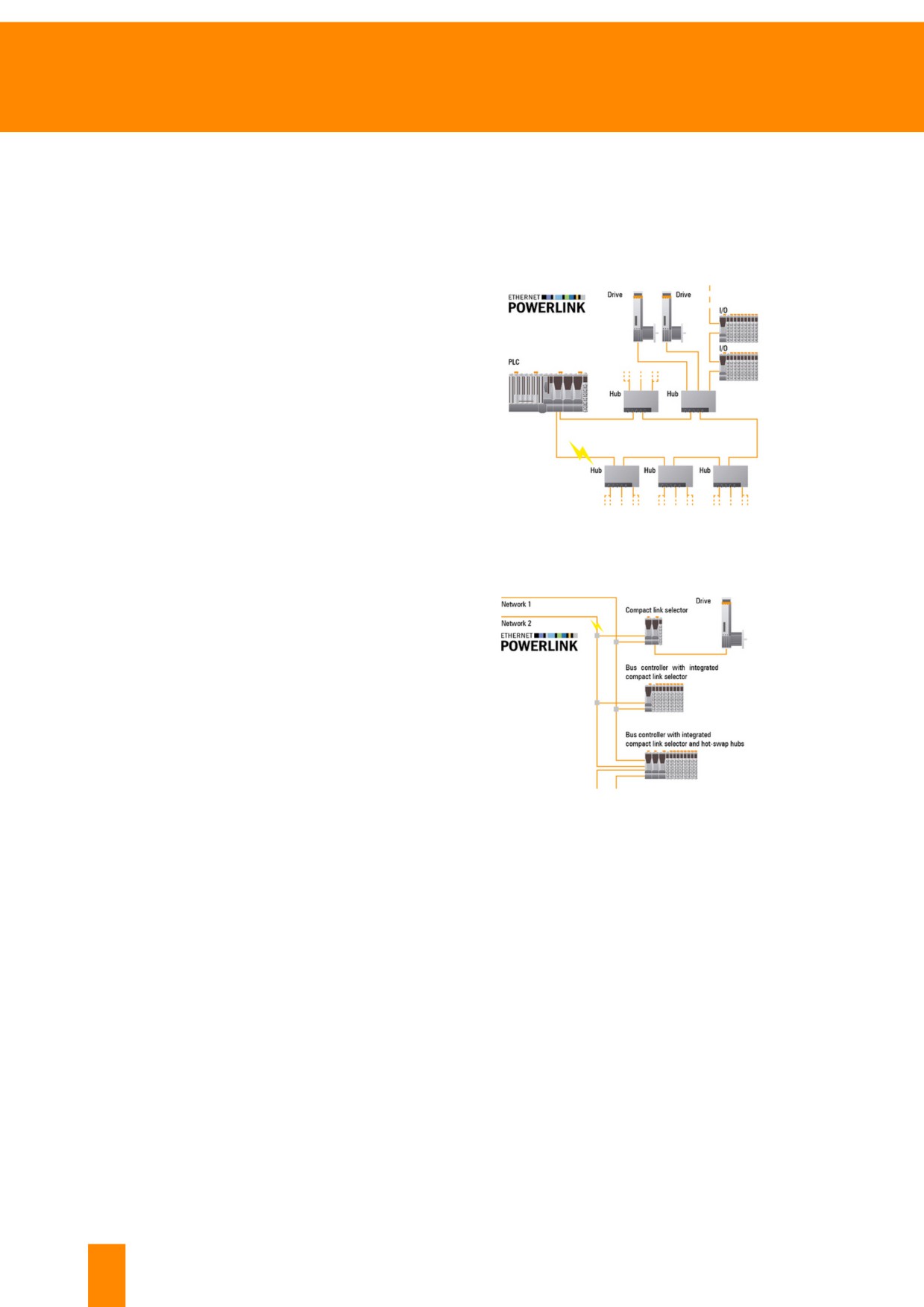
The B&R system offers a variety of redundancy options in order to maximize the availability of machines.
When using POWERLINK, it is possible to choose between ring redundancy and cable redundancy. In
addition, controller redundancy is also available.
Ring redundancy
For ring redundancy, devices are connected in a
line, with the last unit connected back to the mas-
ter. When the connection is interrupted, the ring re-
dundancy manager reacts by feeding in data from
both sides. The master recognizes when the ring
is closed again and once again supplies data only
from one side into the ring. This guarantees con-
tinuous communication.
Interruption of the ring can be evaluated on the
controller using data points or on the modules us-
ing the LEDs. The diagnostic data points are also
Figure: Example of ring redundancy
shown in System Diagnostics Manager (SDM).
Cable redundancy
In this form of network redundancy, two networks
are available and every device is connected to both
networks. If an error occurs on one network, the
link selector recognizes this and switches to the
other. This solution also ensures maximum avail-
ability of machinery and equipment.
Figure: Example of cable redundancy
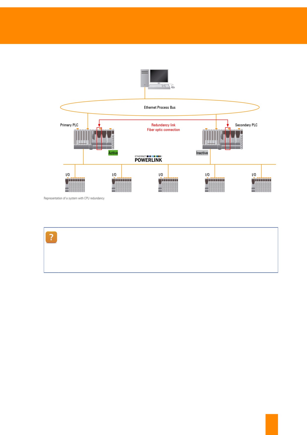
Controller redundancy
B&R's controller redundancy solution ensures maximum availability for entire systems as well as indi-
vidual machines. Controller redundancy allows data to be synchronized within microseconds with no
more than 2 cycles lost when switching over to the respective controller. This functionality is seamlessly
integrated in the real-time operating system and is easy to use.
18
TM920 - Diagnostics and service
System overview and topologies
A second, identical X20 CPU is added to the existing control topology and configured as redundant in
the software.
Figure 9: Schematic representation of controller redundancy with connection to the process bus
The user's manual "Redundancy for control systems" can be downloaded from the B&R
website. For options and examples on the subject of redundancy, refer to the user's manual
available via the following path:
Downloads \ Control and I/O Systems \ X20 system \ Hub & redundancy system \ X20 redun-
dancy system
TM920 - Diagnostics and service
19
Obtaining information about the B&R system
4 Obtaining information about the B&R system
B&R offers its customers a variety of information. All information is
available online around the clock and is constantly updated.
Product-specific information can be found by entering the serial
number on the B&R website. The corresponding data sheets and
user's manuals can be easily downloaded. More details about the
exact procedure is explained in the following chapters.
4.1 Serial numbers and model numbers
Difference between serial number and model
number
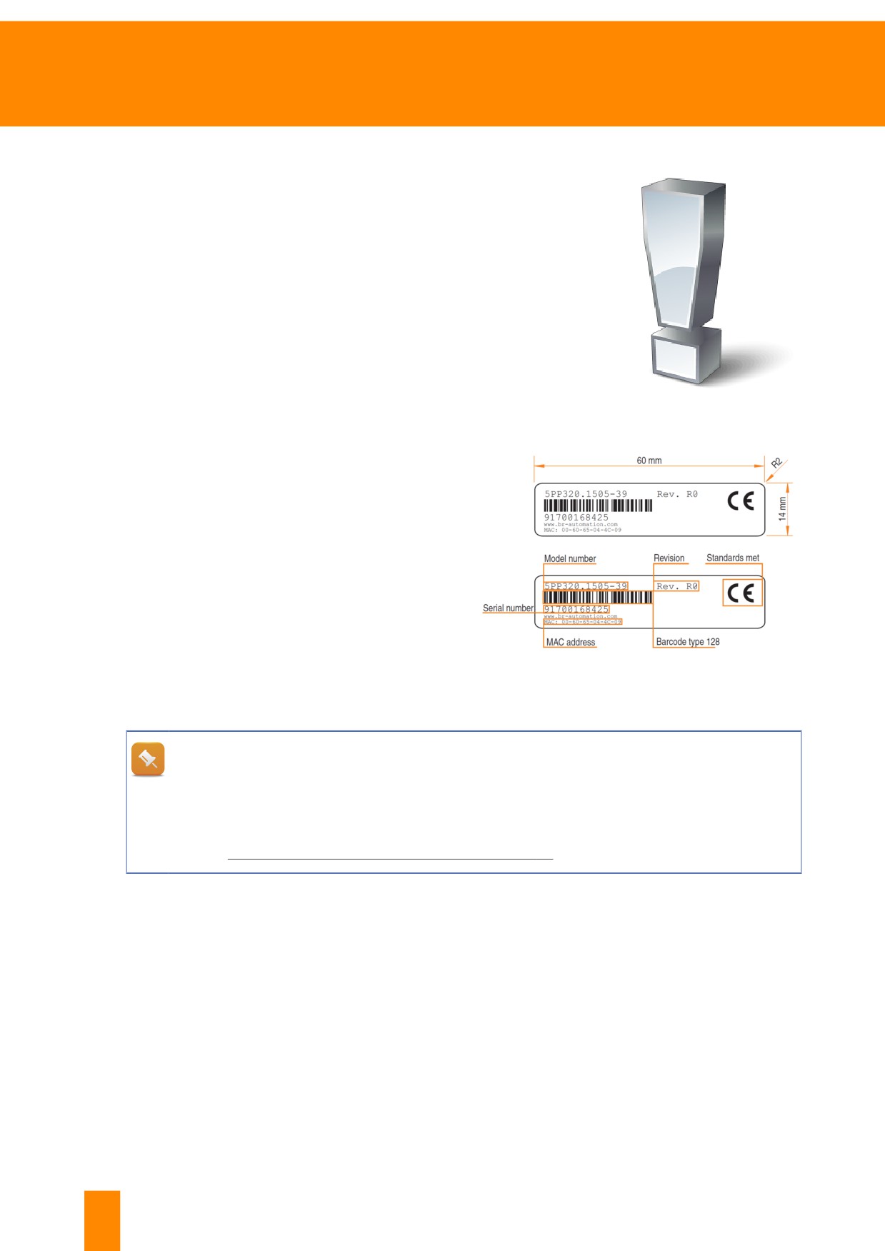
The serial number printed as a barcode is the
unique ID of a B&R product. The serial number
contains the model number, revision, certifications
and the entire history of the component.
The model number is the unique identification of
modules of the same type and is used, for example,
to order modules. This is why the material number
is called model number.
Figure 10: Elements of the serial number sticker
What information does the serial number provide?
Information about a specific serial number can be found using the search function on the B&R
website.
Further information:
•
4.4.3 "Search function of the website" on page 28
20
TM920 - Diagnostics and service
Obtaining information about the B&R system
Attaching the serial number
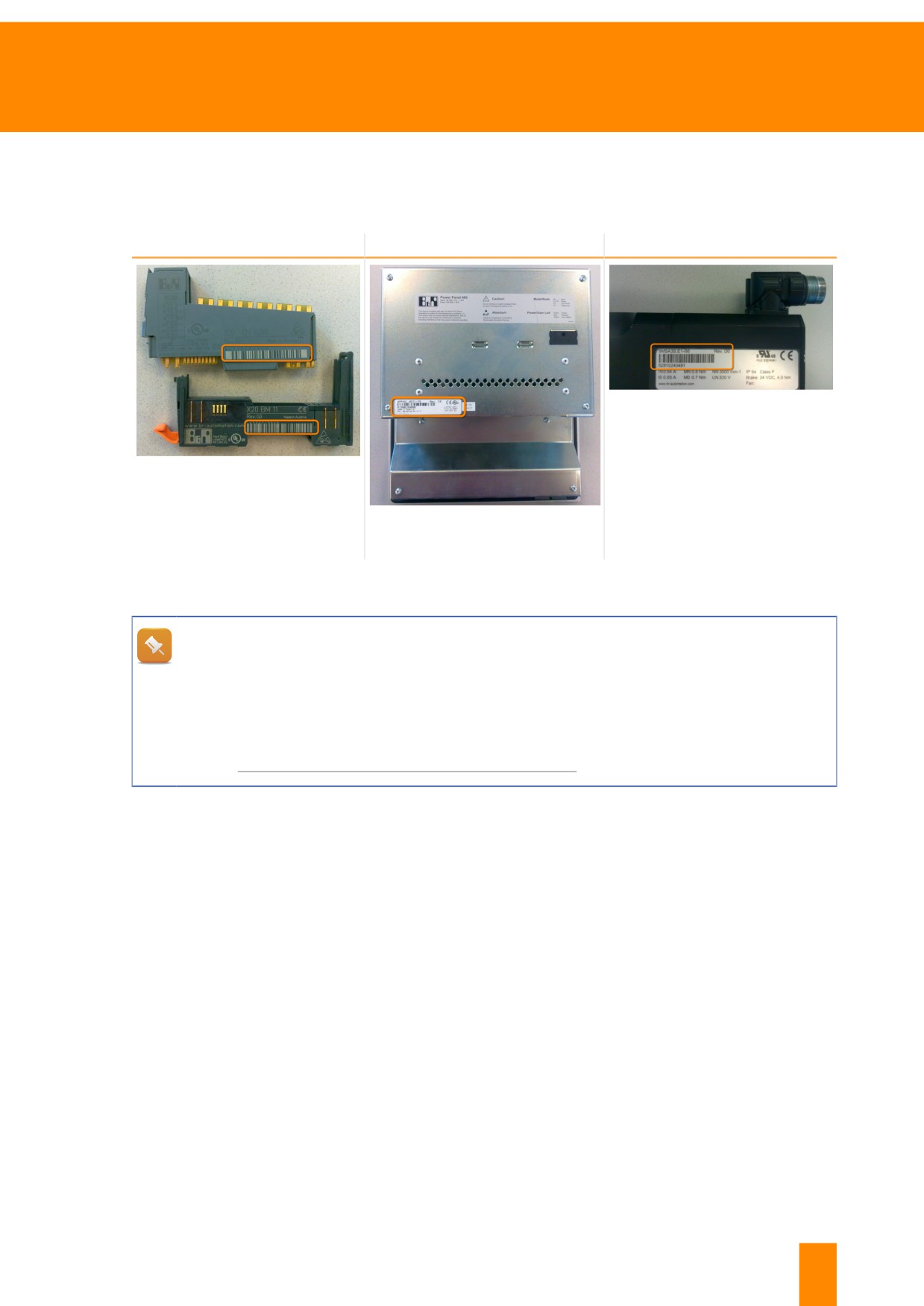
The serial number is found on a free space on each B&R product. On devices with plastic housing, the
data is laser-engraved directly onto the surface. On metal housing it is printed on a white sticker.
X20 system
HMI devices
Motors
Figure 13: Side view of motor
Figure 11: X20 digital module, X20
backplane module
Figure 12: Rear side of Power Panel
Table 3: Examples of serial number placement
Is the serial number visible in the software?
Machine manufacturers have the option of reading serial numbers in the control program. Alter-
natively, the serial numbers of detected hardware can be viewed in System Diagnostics Man-
ager and a list of them can be downloaded from the controller.
Further information:
•
6.5 "Information in the hardware tree" on page 48
TM920 - Diagnostics and service
21
Obtaining information about the B&R system
Exercise: Serial number search
Use the CPU's serial number, integrated in the practice setup, to find out what information is available.
1) Identify the serial number of the CPU
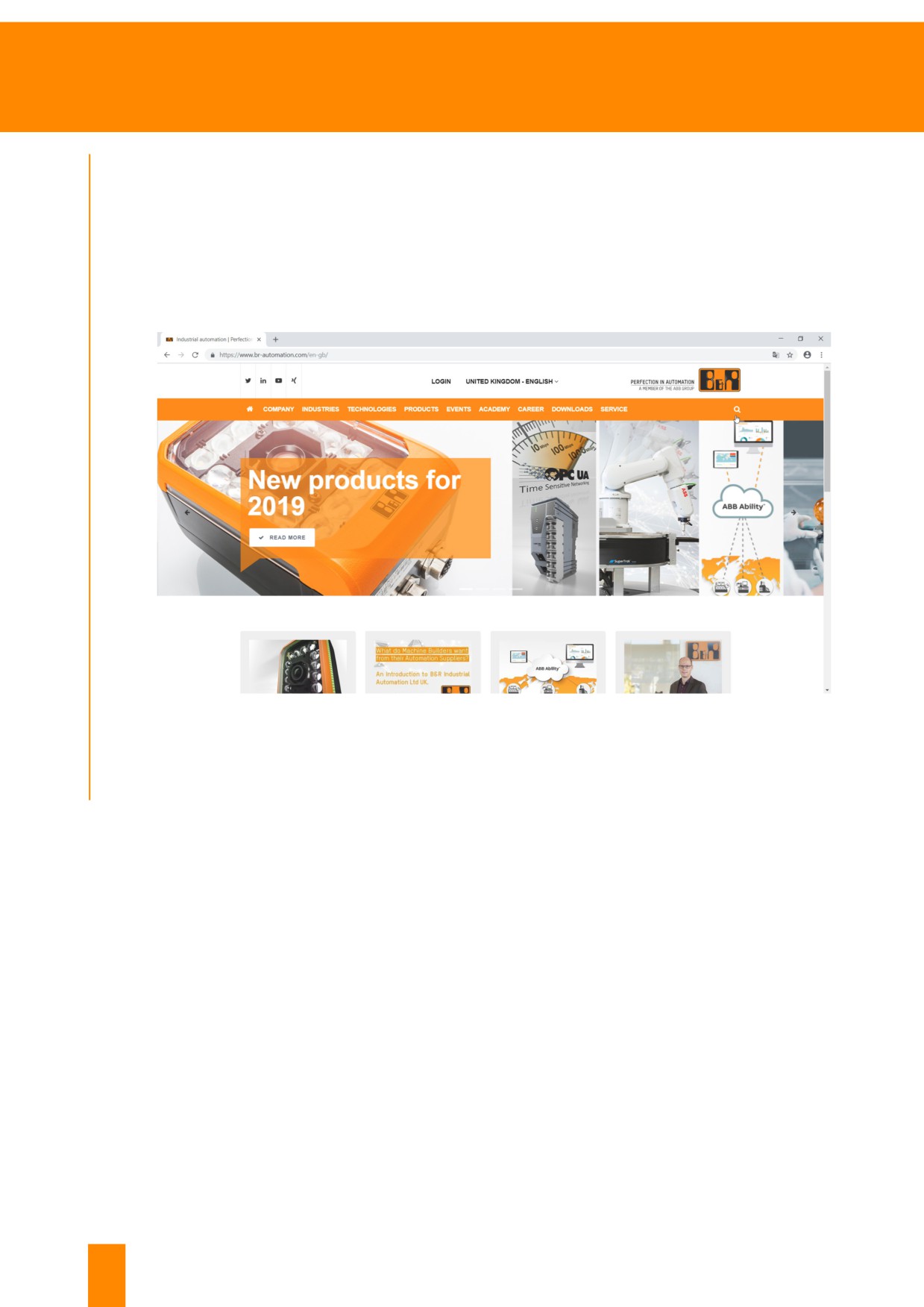
2) Visit the B&R website, www.br-automation.com
3) Enter the serial number in the search field in the upper right corner
Figure 14: The search function is located in the upper right corner behind the magnifying glass
4) Note down results and evaluate them
22
TM920 - Diagnostics and service
Obtaining information about the B&R system
4.2 Data sheets and user's manuals
Data sheets and user's manuals are available on the B&R website.
User's manualscontain complete documentation of the system characteristics, installation and mainte-
nance guidelines, electrical installation and data sheets for each module of a product category.
Data sheetscontain information about a specific module. They document each module including general
technical data, pinouts, equivalent circuit diagrams and a register description.
Where can user's manuals and data sheets be downloaded?
All B&R documents can be found on the B&R website.
There are 3 ways to find the desired document:
• Via the product section
• Via the search function
• Via the download section
The procedure for downloading the X20 system user's manual from the B&R website will be
explained later.
Further information:
•
4.4 "B&R website functions" on page 24
4.3 Structure of B&R user's manuals
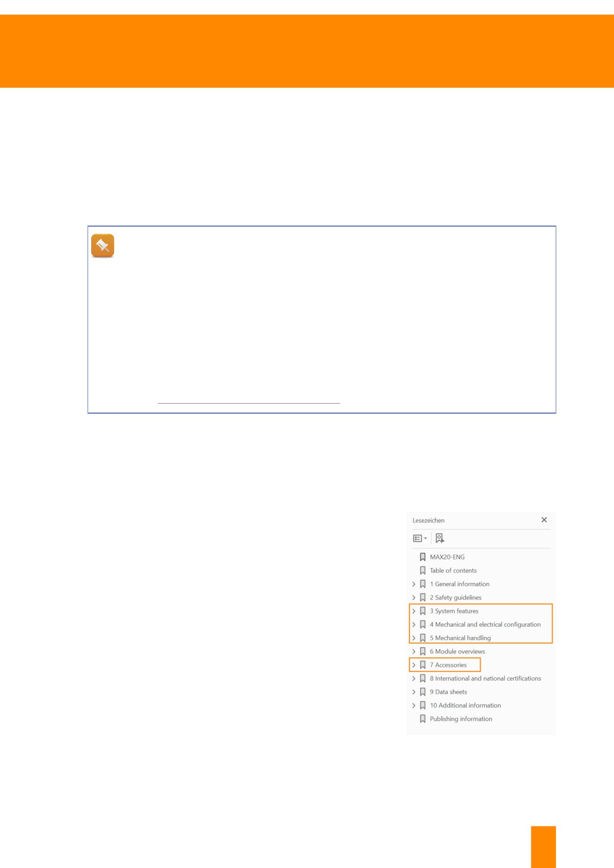
A B&R user's manual is available for each product group. All product variants are described in the user's
manual. Therefore, it serves as reference documentation for the respective system. It contains all rele-
vant data for installation, commissioning and maintenance.
Contents of a B&R user's manual:
• System characteristics
• Mechanical characteristics
• Electrical characteristics
• Installation instructions
• Module descriptions
• Technical data
• LED status indicators
• Maintenance guidelines
• Mechanical handling
• Standards and certifications
• Danger, warning and safety notices
Figure 15: Table of Contents of the X20
system user's manual
TM920 - Diagnostics and service
23
Obtaining information about the B&R system
Search within the user's manual
In order to obtain information on a single product variant, it is advisable to search for the model
number in the PDF of the user's manual. This is the quickest way to find the information you
need.
Exercise: Search for and download the X20 user's manual
This exercise involves searching for and downloading a user's man-
ual from the B&R website. After that, the task is to gain an overview
of the contents and structure of the manual.
Search for the following information in the X20 user's man-
ual:
• Size of the X20CP1586 product's working memory
• Connection of the supply to the terminal and the supply
voltage range of the X20CP1586 product
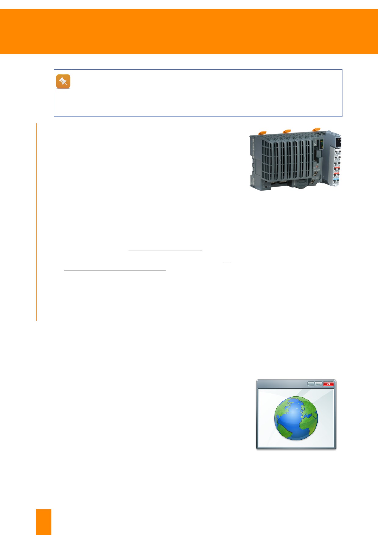
Figure 16: X20 CPU - X20CP1586
• Different shielding concepts on X2010 Modules
• Steps for mounting or dismounting the X20 system
• Replacing the backup battery
1) Visit the B&R website, www.br-automation.com
2) Search for the X20 system user's manual. For help, see 4.4
"B&R website functions" on page 24
3) Download user's manual
4) Search for product data and general information
5) Note down results and evaluate them
4.4 B&R website functions
The B&R website provides up-to-date information on all B&R products. The comprehensive search func-
tion with different filters facilitates the targeted search for information.
The following information can be found on the B&R web-
site:
• Product catalogs, user's manuals
• Data sheets, certificates
• Drivers, updates, CAD data
• B&R worldwide contact info
• Support Portal, Material Return Portal
• Global search function, e.g. for serial
and model numbers
• And much more...
10 This exercise can also be performed for a different B&R control system if an X20 system is not being
used.
24
TM920 - Diagnostics and service
Obtaining information about the B&R system
An example of how to download B&R documents from the website are shown in each of the following
chapters.
There are 3 ways to find the desired document:
•
4.4.1 "Product section on the website" on page 25
•
4.4.3 "Search function of the website" on page 28
•
4.4.4 "Download section of the website" on page 29
4.4.1 Product section on the website
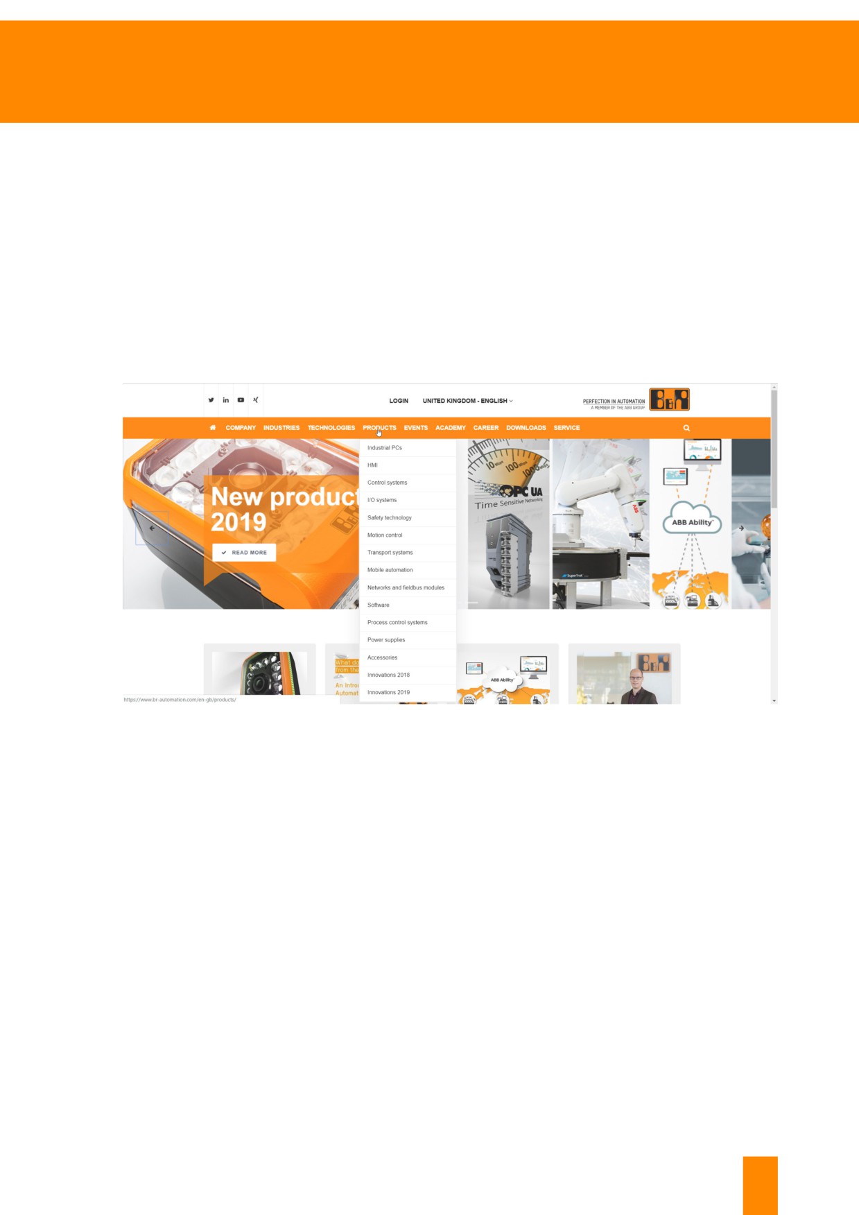
Information about B&R's range of products can be found in the product section of the B&R website.
www.br-automation.com→ "Products" in the main menu
Figure 17: The different product groups can be opened via the main menu
TM920 - Diagnostics and service
25
Obtaining information about the B&R system
Download X20 system user's manual from the product section
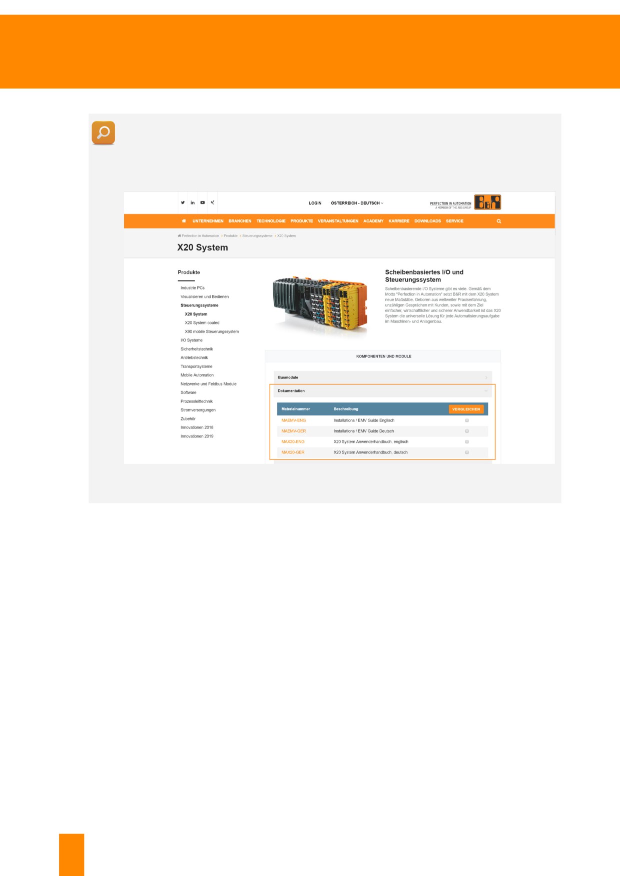
Navigate to "Control systems" via the product section. Then, select "X20 system". Scroll down to
category "Documentation". When this category is open, click on the X20 user's manual "MAX20-
GER". A new page opens. The user's manual can now be downloaded in the "Downloads" tab.
Figure 18: The X20 system user's manual can be downloaded from the product section.
26
TM920 - Diagnostics and service
Obtaining information about the B&R system
4.4.2 Compare products
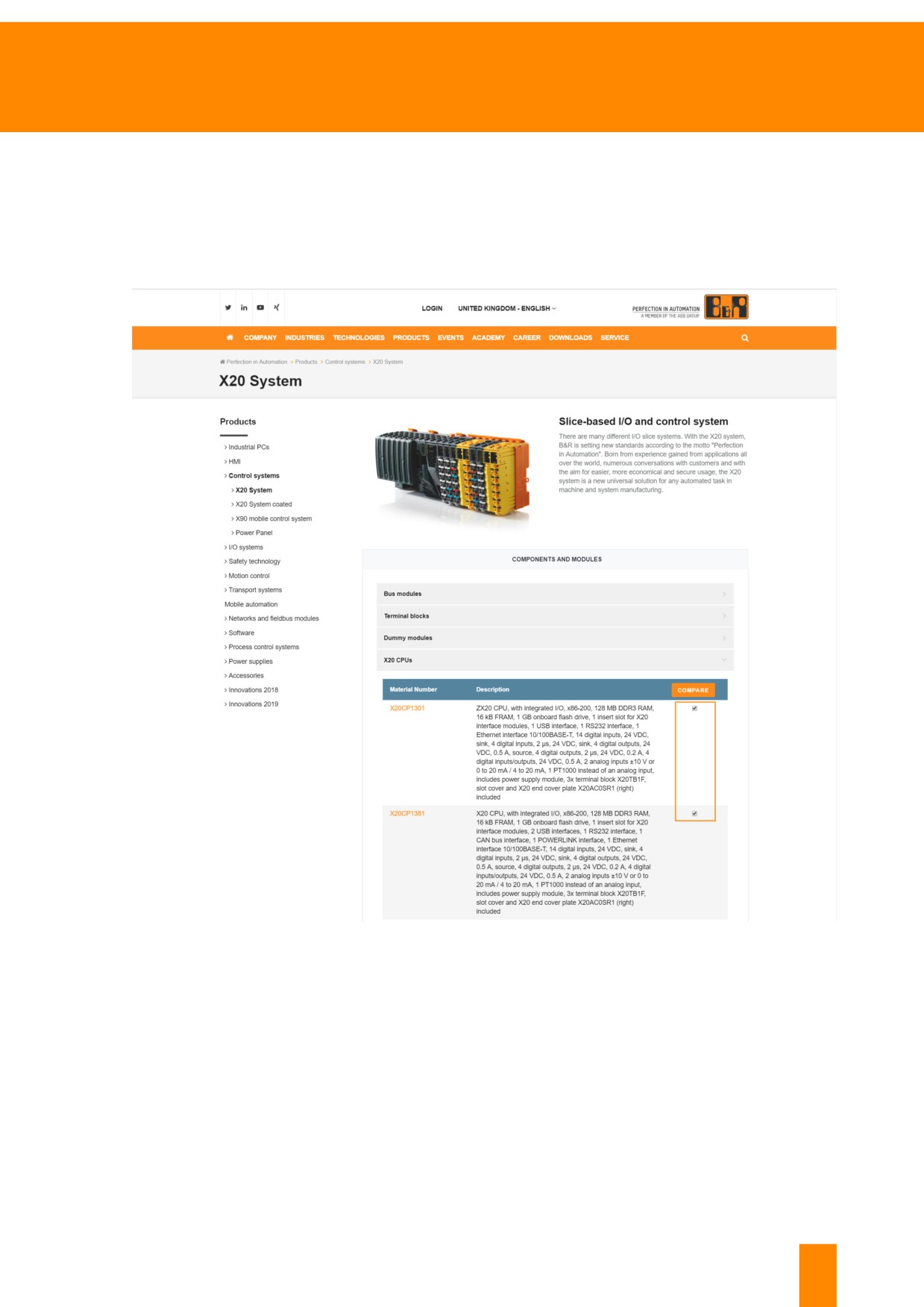
The available variants of each B&R product are listed in the product section. The product variants are
compared by selecting the checkbox of the respective variant. Then, click on the "Compare" button to
open the comparison.
Figure 19: The checkboxes of the X20 product variants "X20CP1301" and "X20CP1381" are marked
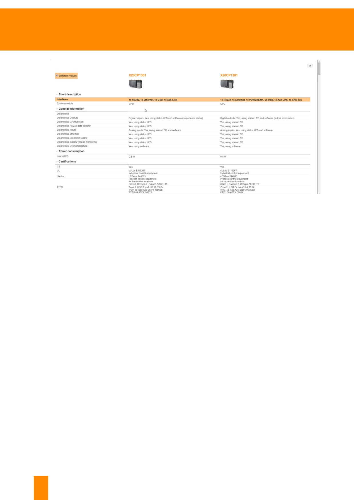
After clicking on "Compare", the detailed product comparison opens. Differences and similarities be-
tween the two product variants are shown in a table and highlighted in color.
TM920 - Diagnostics and service
27
Obtaining information about the B&R system
Figure 20: Differences between the selected variants are highlighted in color
4.4.3 Search function of the website
The search field is located at the top right of the B&R website.
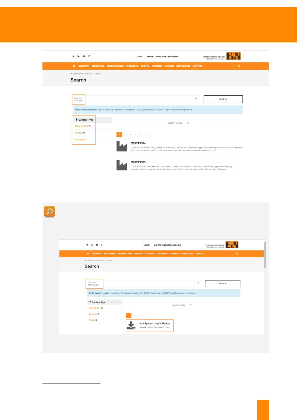
Serial numbers or product names are suitable as search terms, for example. When searching for a
product whose name starts with "X20CP1", it is recommended to enter "X20CP1*" to get optimal results.
The results matching the search term are categorized. The results can be filtered according to these
four different categories under "Content type".
The following categories are available for the search result:
• Page content
• Product
• Download
• Press releases
28
TM920 - Diagnostics and service
Obtaining information about the B&R system
Figure 21: Results for "X20CP1*". Under "Content type", results can be filtered by category.
Download the "X20 system user's manual" using the search function
Enter "X20 user's manual" in the search box at the top right and press ENTER (if the desired
result is not included, results can be filtered by content type "Download"). Clicking on the result
opens another page from which the user's manual can be downloaded.
Figure 22: The "X20 system user's manual" can be downloaded via the search function.
4.4.4 Download section of the website
Downloadable contents can be found on the B&R website in the "Download" section.
www.br-automation.com→ In main menu "Downloads"
TM920 - Diagnostics and service
29
Obtaining information about the B&R system
The following content can be found in the Downloads section:
■
Data sheets
■
User's manuals
■
Catalogs
■
Drivers and updates
■
Tools
■
Certificates
■
And much more...
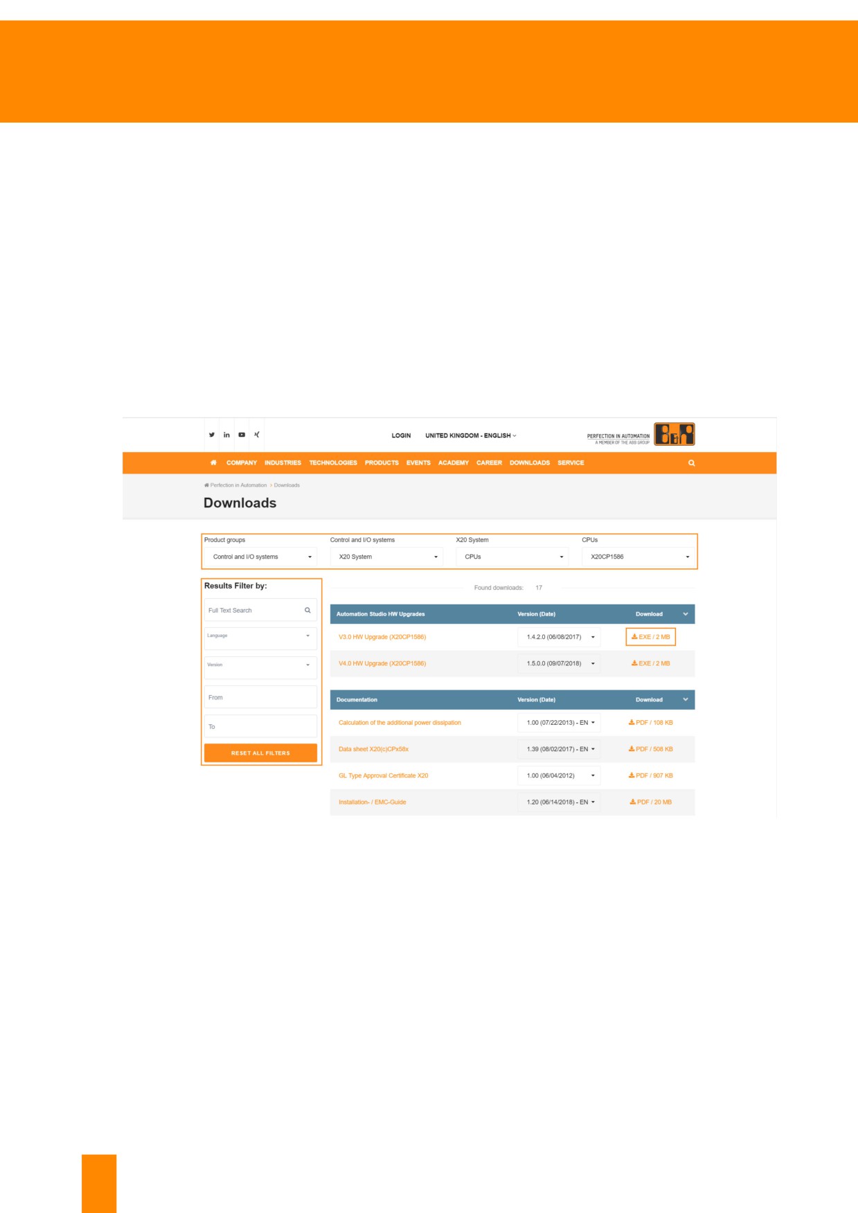
The "Product groups" drop-down box is available to search for specific content. When a product group
is selected, additional drop-down boxes are loaded to limit the content displayed.
The filters to the left of the results allow even more precise filtering.
The content will be downloaded as soon as you click on the download icon to the right of the entry.
Figure 23: To get access to the download section of product "X20CP1586", product group "Control and I/O Systems" must be
selected
30
TM920 - Diagnostics and service
Obtaining information about the B&R system
Download the "X20 System user's manual" from the download section
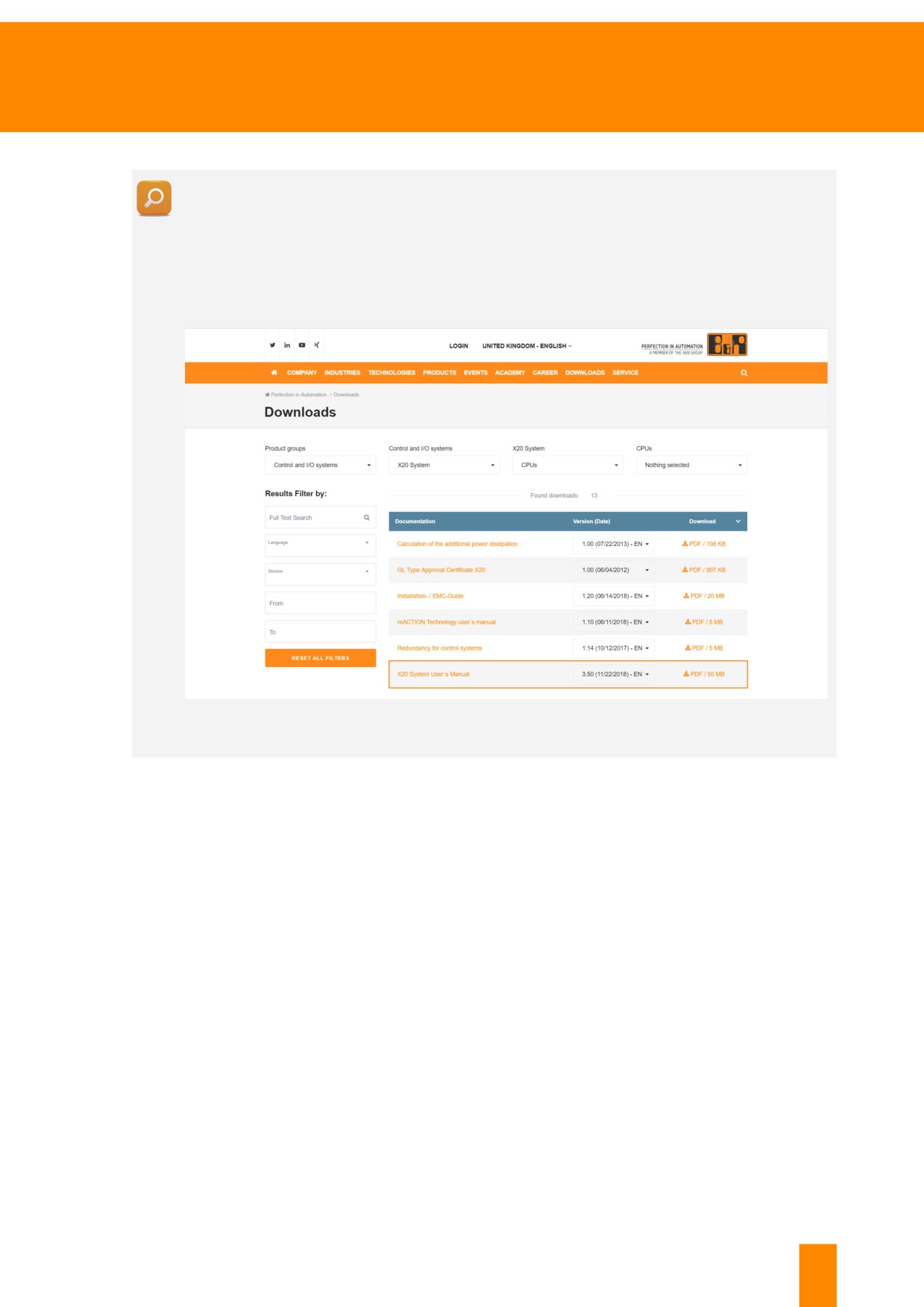
Use section "Downloads" to navigate to the general download section. Then select option "Con-
trol and I/O Systems" from drop-down menu "Product Group". Select "X20 system" and "Central
units" from the drop-down menus that follow.
Scroll down to category "Documentation". Clicking on the result opens another page from which
the user's manual can be downloaded.
Figure 24: The X20 system user's manual can be downloaded from section "Downloads"
TM920 - Diagnostics and service
31
///////////////////////////////////////