Cisco Industrial Ethernet 4000, 4010 and 5000 Switch Software. Configuration Guide (2022) - page 34
Configuring IP Unicast Routing
Configuring Multi-VRF CE
Information About Multi-VRF CE
Multi-VRF CE allows a service provider to support two or more VPNs, where IP addresses can be overlapped among the
VPNs. Multi-VRF CE uses input interfaces to distinguish routes for different VPNs and forms virtual packet-forwarding
tables by associating one or more Layer 3 interfaces with each VRF. Interfaces in a VRF can be either physical, such as
Ethernet ports, or logical, such as VLAN SVIs, but an interface cannot belong to more than one VRF at any time.
Note: Multi-VRF CE interfaces must be Layer 3 interfaces.
Multi-VRF CE includes these devices:
Customer edge (CE) devices provide customers access to the service-provider network over a data link to one or
more provider edge routers. The CE device advertises the site local routes to the router and learns the remote VPN
routes from it. The Cisco Connected Grid switch can be a CE.
Provider edge (PE) routers exchange routing information with CE devices by using static routing or a routing protocol
such as BGP, RIPv2, OSPF, or EIGRP. The PE is only required to maintain VPN routes for those VPNs to which it is
directly attached, eliminating the need for the PE to maintain all of the service-provider VPN routes. Each PE router
maintains a VRF for each of its directly connected sites. Multiple interfaces on a PE router can be associated with a
single VRF if all of these sites participate in the same VPN. Each VPN is mapped to a specified VRF. After learning
local VPN routes from CEs, a PE router exchanges VPN routing information with other PE routers by using internal
BGP (IBPG).
Provider routers or core routers are any routers in the service provider network that do not attach to CE devices.
With multi-VRF CE, multiple customers can share one CE, and only one physical link is used between the CE and the PE.
The shared CE maintains separate VRF tables for each customer and switches or routes packets for each customer based
on its own routing table. Multi-VRF CE extends limited PE functionality to a CE device, giving it the ability to maintain
separate VRF tables to extend the privacy and security of a VPN to the branch office.
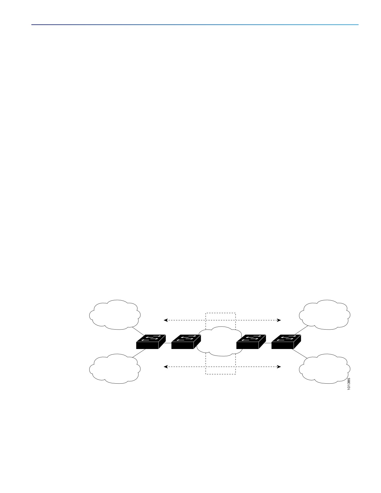
Figure 106 on page 937 shows a configuration using Cisco Connected Grid switches as multiple virtual CEs. This
scenario is suited for customers who have low bandwidth requirements for their VPN service, for example, small
companies. In this case, multi-VRF CE support is required in the Cisco Connected Grid switches. Because multi-VRF CE
is a Layer 3 feature, each interface in a VRF must be a Layer 3 interface.
Figure 106 Switches Acting as Multiple Virtual CEs
VPN 1
VPN 1
CE1
PE1
PE2
CE2
Service
provider
VPN 2
VPN 2
CE = Customer-edge device
PE = Provider-edge device
When the CE switch receives a command to add a Layer 3 interface to a VRF, it sets up the appropriate mapping between
the VLAN ID and the policy label (PL) in multi-VRF-CE-related data structures and adds the VLAN ID and PL to the VLAN
database.
When multi-VRF CE is configured, the Layer 3 forwarding table is conceptually partitioned into two sections:
The multi-VRF CE routing section contains the routes from different VPNs.
937

Configuring IP Unicast Routing
Configuring Multi-VRF CE
The global routing section contains routes to non-VPN networks, such as the Internet.
VLAN IDs from different VRFs are mapped into different policy labels, which are used to distinguish the VRFs during
processing. If no route is found in the multi-VRF CE section of the Layer 3 forwarding table, the global routing section is
used to determine the forwarding path. For each new VPN route learned, the Layer 3 setup function retrieves the policy
label by using the VLAN ID of the ingress port and inserts the policy label and new route to the multi-VRF CE routing
section. If the packet is received from a routed port, the port internal VLAN ID number is used; if the packet is received
from an SVI, the VLAN number is used.
This is the packet-forwarding process in a multi-VRF-CE-enabled network:
When the switch receives a packet from a VPN, the switch looks up the routing table based on the input policy label
number. When a route is found, the switch forwards the packet to the PE.
When the ingress PE receives a packet from the CE, it performs a VRF lookup. When a route is found, the router adds
a corresponding MPLS label to the packet and sends it to the MPLS network.
When an egress PE receives a packet from the network, it strips the label and uses the label to identify the correct
VPN routing table. Then it performs the normal route lookup. When a route is found, it forwards the packet to the
correct adjacency.
When a CE receives a packet from an egress PE, it uses the input policy label to look up the correct VPN routing
table. If a route is found, it forwards the packet within the VPN.
To configure VRF, you create a VRF table and specify the Layer 3 interface associated with the VRF. Then configure the
routing protocols in the VPN and between the CE and the PE. BGP is the preferred routing protocol used to distribute
VPN routing information across the provider’s backbone. The multi-VRF CE network has three major components:
VPN route target communities—lists of all other members of a VPN community. You need to configure VPN route
targets for each VPN community member.
Multiprotocol BGP peering of VPN community PE routers—propagates VRF reachability information to all members of
a VPN community. You need to configure BGP peering in all PE routers within a VPN community.
VPN forwarding—transports all traffic between all VPN community members across a VPN service-provider network.
Default Multi-VRF CE Configuration
Feature
Default Setting
VRF
Disabled. No VRFs are defined.
Maps
No import maps, export maps, or route maps are defined.
VRF maximum routes
5000
Forwarding table
The default for an interface is the global routing table.
Multi-VRF CE Configuration Guidelines
These are considerations when configuring VRF in your network:
A switch with multi-VRF CE is shared by multiple customers, and each customer has its own routing table.
Because customers use different VRF tables, the same IP addresses can be reused. Overlapped IP addresses are
allowed in different VPNs.
Multi-VRF CE lets multiple customers share the same physical link between the PE and the CE. Trunk ports with
multiple VLANs separate packets among customers. Each customer has its own VLAN.
938
Configuring IP Unicast Routing
Configuring Multi-VRF CE
Multi-VRF CE does not support all MPLS-VRF functionality. It does not support label exchange, LDP adjacency, or
labeled packets.
For the PE router, there is no difference between using multi-VRF CE or using multiple CEs. In Figure 106 on
page 937, multiple virtual Layer 3 interfaces are connected to the multi-VRF CE device.
The switch supports configuring VRF by using physical ports, VLAN SVIs, or a combination of both. The SVIs can be
connected through an access port or a trunk port.
A customer can use multiple VLANs as long as they do not overlap with those of other customers. A customer’s
VLANs are mapped to a specific routing table ID that is used to identify the appropriate routing tables stored on the
switch.
The switch supports one global network and up to 26 VRFs.
Most routing protocols (BGP, OSPF, RIP, EIGRP, and static routing) can be used between the CE and the PE. However,
we recommend using external BGP (EBGP) for these reasons:
— BGP does not require multiple algorithms to communicate with multiple CEs.
— BGP is designed for passing routing information between systems run by different administrations.
— BGP makes it easy to pass attributes of the routes to the CE.
Multi-VRF CE does not affect the packet switching rate.
If no VRFs are configured, up to 105 policies can be configured.
If even one VRF is configured than 41 policies can be configured.
If more than 41 policies are configured then VRF cannot be configured.
VRF and private VLANs are mutually exclusive. You cannot enable VRF on a private VLAN. Similarly, you cannot
enable private VLAN on a VLAN with VRF configured on the VLAN interface.
VRF and policy-based routing (PBR) are mutually exclusive on a switch interface. You cannot enable VRF when PBR
is enabled on an interface. In contrast, you cannot enable PBR when VRF is enabled on an interface.
Configuring VRFs
Follow the steps in this procedure to configure one or more VRFs.
BEFORE YOU BEGIN
See Multi-VRF CE Configuration Guidelines, page 938.
939

Configuring IP Unicast Routing
Configuring Multi-VRF CE
DETAILED STEPS
Command
Purpose
1.
configure terminal
Enter global configuration mode.
2.
ip routing
Enable IP routing.
3.
ip vrf vrf-name
Name the VRF, and enter VRF configuration mode.
4.
rd route-distinguisher
Create a VRF table by specifying a route distinguisher. Enter
either an AS number and an arbitrary number (xxx:y) or an IP
address and arbitrary number (A.B.C.D:y).
5.
route-target {export | import |
Create a list of import, export, or import and export route target
both} route-target-ext-community
communities for the specified VRF. Enter either an AS system
number and an arbitrary number (xxx:y) or an IP address and
an arbitrary number (A.B.C.D:y). The
route-target-ext-community should be the same as the
route-distinguisher entered in Step 4.
6.
import map route-map
(Optional) Associate a route map with the VRF.
7.
interface interface-id
Specify the Layer 3 interface to be associated with the VRF, and
enter interface configuration mode. The interface can be a
routed port or SVI.
8.
no shutdown
Enable the interface if necessary. By default, UNIs and ENIs are
disabled and NNIs are enabled.
9.
ip vrf forwarding vrf-name
Associate the VRF with the Layer 3 interface.
10.
end
Return to privileged EXEC mode.
11.
show ip vrf [brief | detail |
Verify the configuration. Display information about the
interfaces] [vrf-name]
configured VRFs.
12.
copy running-config
(Optional) Save your entries in the configuration file.
startup-config
Use the no ip vrf vrf-name global configuration command to delete a VRF and to remove all interfaces from it. Use the
no ip vrf forwarding interface configuration command to remove an interface from the VRF.
EXAMPLE
The following example shows how to import a route map to a VRF instance named VPN1:
Switch(config)# ip vrf vpn1
Switch(config-vrf)# rd 100:2
Switch(config-vrf)# route-target both 100:2
Switch(config-vrf)# route-target import 100:1
Configuring VRF-Aware Services
IP services can be configured on global interfaces, and these services run within the global routing instance. IP services
are enhanced to run on multiple routing instances; they are VRF-aware. Any configured VRF in the system can be
specified for a VRF-aware service.
VRF-aware services are implemented in platform-independent modules. VRF means multiple routing instances in Cisco
IOS. Each platform has its own limit on the number of VRFs it supports.
VRF-aware services have the following characteristics:
The user can ping a host in a user-specified VRF.
940

Configuring IP Unicast Routing
Configuring Multi-VRF CE
ARP entries are learned in separate VRFs. The user can display Address Resolution Protocol (ARP) entries for
specific VRFs.
These services are VRF-aware:
ARP
Ping
Simple Network Management Protocol (SNMP)
Hot Standby Router Protocol (HSRP)
Syslog
Traceroute
FTP and TFTP
Note: VRF-aware services are not supported for Unicast Reverse Path Forwarding (uRPF).
User Interface for ARP
Use the arp command in global configuration mode to add a VRF to the ARP cache.
BEFORE YOU BEGIN
Configure a VRF as described in the Configuring VRFs, page 939.
DETAILED STEPS
Command
Purpose
1.
configure terminal
Enter global configuration mode.
2.
arp vrf vrf-name hardware-address
Add a VRF instance. The vrf-name argument is the name of
encap-type [interface-type] [alias]
the VRF table.
3.
end
Return to privileged EXEC mode.
4.
copy running-config
(Optional) Save your entries in the configuration file.
startup-config
EXAMPLE
switch(config)# arp vrf vpn1 0800.0900.1834
User Interface for PING
To check if a configured VRF is working, you can use the ping vrf command.
When attempting to ping from a provider edge (PE) router to a customer edge (CE) router, or from a PE router to PE router,
the standard ping command will not usually work. The ping vrf command allows you to ping the IP addresses of LAN
interfaces on CE routers.
If you are on a PE router, be sure to indicate the specific VRF (VPN) name, as shown in the “Examples” section.
If all required information is not provided at the command line, the system will enter the interactive dialog (extended
mode) for ping.
941

Configuring IP Unicast Routing
Configuring Multi-VRF CE
BEFORE YOU BEGIN
Configure a VRF as described in the Configuring VRFs, page 939.
DETAILED STEPS
Command
Purpose
1.
ping vrf vrf-name ip-host
Tests a connection in the context of a specific VPN connection.
EXAMPLE
In the following example, the target host in the domain 209.165.201.1 is pinged (using IP/ICMP) in the context of the
“CustomerA” VPN connection:
Switch# ping vrf CustomerA 209.165.201.1
Type escape sequence to abort.
Sending 5, 100-byte ICMP Echos to 209.165.201.1, timeout is 2 seconds:
!!!!!
Success rate is 100 percent (5/5), round-trip min/avg/max = 176/264/576 ms
User Interface for SNMP
Follow the steps in this procedure to configure configure VRF-aware services for SNMP.
BEFORE YOU BEGIN
Configure a VRF as described in the Configuring VRFs, page 939.
DETAILED STEPS
Command
Purpose
1.
configure terminal
Enter global configuration mode.
2.
snmp-server trap authentication
Enable VRF instance context authentication notifications.
vrf
3.
snmp-server engineID remote
Configure a name for the remote SNMP engine on a switch.
<host> vrf <vpn instance>
<engine-id string>
4.
snmp-server host <host> vrf <vpn
Specify the recipient of an SNMP trap operation and specify
instance> traps <community>
the VRF table to be used for sending SNMP traps.
5.
snmp-server host <host> vrf <vpn
Specify the recipient of an SNMP inform operation and specify
instance> informs <community>
the VRF table to be used for sending SNMP informs.
6.
snmp-server user <user> <group>
Add a user to an SNMP group for a remote host on a VRF for
remote <host> vrf <vpn instance>
SNMP access.
<security model>
7.
end
Return to privileged EXEC mode.
8.
copy running-config
(Optional) Save your entries in the configuration file.
startup-config
EXAMPLE
The following example specifies the SNMP engine ID and configures the VRF name traps-vrf for SNMP communications
with the remote device at 172.16.20.3:
Switch(config)# snmp-server engineID remote 172.16.20.3 vrf trap-vrf 80000009030000B064EFE100
942

Configuring IP Unicast Routing
Configuring Multi-VRF CE
The following example shows how to send all SNMP notifications to example.com over the VRF named trap-vrf using the
community string public:
Switch(config)# snmp-server host example.com vrf trap-vrf public
User Interface for HSRP
Hot Standby Router Protocol (HSRP) support for VRFs ensures that HSRP virtual IP addresses are added to the correct
IP routing table.
BEFORE YOU BEGIN
Configure a VRF as described in the Configuring VRFs, page 939.
DETAILED STEPS
Command
Purpose
1.
configure terminal
Enter global configuration mode.
2.
interface interface-id
Enter interface configuration mode, and specify the Layer 3
interface to configure.
3.
no switchport
Remove the interface from Layer 2 configuration mode if it is a
physical interface.
4.
ip vrf forwarding <vrf-name>
Configure VRF on the interface.
Executing this command on an interface removes the IP
address.
5.
ip address ip address
Enter the IP address for the interface.
6.
standby 1 ip ip address
Enable HSRP and configure the virtual IP address.
7.
end
Return to privileged EXEC mode.
8.
copy running-config
(Optional) Save your entries in the configuration file.
startup-config
EXAMPLE
Switch(config)# interface ethernet 0
Switch(config-if)# no switchport
Switch(config-if)# ip vrf forwarding vpn1
Switch(config-if)# ip address 172.16.1.3
Switch(config-if)# standby 1 ip
User Interface for Syslog
Follow the steps in this procedure to configure VRF-aware services for Syslog.
BEFORE YOU BEGIN
Configure a VRF as described in the Configuring VRFs, page 939.
943

Configuring IP Unicast Routing
Configuring Multi-VRF CE
DETAILED STEPS
Command
Purpose
1.
configure terminal
Enter global configuration mode.
2.
logging on
Enable or temporarily disable logging of storage router event
message.
3.
logging host ip address vrf vrf
Specify the host address of the syslog server where logging
name
messages are to be sent.
4.
logging buffered logging buffered
Log messages to an internal buffer.
size debugging
5.
logging trap debugging
Limit the logging messages sent to the syslog server.
6.
logging facility facility
Send system logging messages to a logging facility.
7.
end
Return to privileged EXEC mode.
8.
copy running-config
(Optional) Save your entries in the configuration file.
startup-config
EXAMPLE
The following example specifies a VRF that connects to the syslog server host:
Switch(config)# logging host 192.168.200.225 vrf vpn1
User Interface for Traceroute
Follow the steps in this procedure to find the destination address in a VRF.
BEFORE YOU BEGIN
Configure a VRF as described in the Configuring VRFs, page 939.
DETAILED STEPS
Command
Purpose
traceroute vrf vrf-name ipaddress
Specify the name of a VPN VRF in which to find the destination
address.
EXAMPLE
The following example displays output of the traceroute command with the vrf keyword. Output includes the incoming
VRF name/tag and the outgoing VRF name/tag.
Switch# traceroute vrf red 10.0.10.12
Type escape sequence to abort.
Tracing the route to 10.0.10.12
VRF info: (vrf in name/id, vrf out name/id)
1 10.1.13.15 (red/13,red/13) 0 msec
10.1.16.16 (red/13,red/13) 0 msec
10.1.13.15 (red/13,red/13) 1 msec
2 10.1.8.13 (red/13,red/13) 0 msec
10.1.7.13 (red/13,red/13) 0 msec
10.1.8.13 (red/13,red/13) 0 msec
3 10.1.2.11 (red/13,blue/10) 1 msec 0 msec 0 msec
4
*
*
*
944

Configuring IP Unicast Routing
Configuring Multi-VRF CE
User Interface for FTP and TFTP
FTP and TFTP are VRF-aware, which means that file transfer is supported across an interface within a VRF instance. To
specify a VRF as a source for FTP or TFTP connections, the VRF must be associated with the same interface that you
configure with the ip ftp source-interface command. In this configuration, FTP looks for the destination IP address for
file transfer in the specified VRF table. If the specified source interface is not up, Cisco IOS software selects the address
of the interface closest to the destination as the source address.
Command
Purpose
1.
configure terminal
Enter global configuration mode.
2.
ip ftp source-interface
Specify the source IP address for FTP connections.
interface-type interface-number
3.
end
Return to privileged EXEC mode.
4.
copy running-config
(Optional) Save your entries in the configuration file.
startup-config
To specify the IP address of an interface as the source address for TFTP connections, use the ip tftp source-interface
show mode command. To return to the default, use the no form of this command.
Command
Purpose
1.
configure terminal
Enter global configuration mode.
2.
ip tftp source-interface
Specify the source IP address for TFTP connections.
interface-type interface-number
3.
end
Return to privileged EXEC mode.
4.
copy running-config
(Optional) Save your entries in the configuration file.
startup-config
EXAMPLE
The following example shows how to configure the switch to use the VRF table named vpn1 to look for the destination
IP address for the transfer of FTP packets:
Switch# configure terminal
Switch(config)# ip ftp source-interface ethernet 0
Switch(config)# ip vrf vpn1
Switch(config-vrf)# rd 200:1
Switch(config-vrf)# route-target both 200:1
Switch(config-vrf)# interface ethernet 0
Switch(config-if)# ip vrf forwarding vpn1
Switch(config-if)# end
User Interface for VRF-Aware RADIUS
To configure VRF-aware RADIUS, you must first enable AAA on a RADIUS server. The switch supports the ip vrf
forwarding vrf-name server-group configuration and the ip radius source-interface global configuration commands.
Configuring a VPN Routing Session
Routing within the VPN can be configured with any supported routing protocol (RIP, OSPF, EIGRP, or BGP) or with static
routing. The configuration shown here is for OSPF, but the process is the same for other protocols.
945

Configuring IP Unicast Routing
Configuring Multi-VRF CE
Note: To configure an EIGRP routing process to run within a VRF instance, you must configure an autonomous-system
number by entering the autonomous-system autonomous-system-number address-family configuration mode
command.
BEFORE YOU BEGIN
Configure a VRF as described in the Configuring VRFs, page 939.
DETAILED STEPS
Command
Purpose
1.
configure terminal
Enter global configuration mode.
2.
router ospf process-id vrf vrf-name
Enable OSPF routing, specify a VPN forwarding table, and
enter router configuration mode.
3.
log-adjacency-changes
(Optional) Log changes in the adjacency state. This is the
default state.
4.
redistribute bgp
Set the switch to redistribute information from the BGP network
autonomous-system-number
to the OSPF network.
subnets
5.
network network-number area
Define a network address and mask on which OSPF runs and
area-id
the area ID for that network address.
6.
end
Return to privileged EXEC mode.
7.
show ip ospf process-id
Verify the configuration of the OSPF network.
8.
copy running-config
(Optional) Save your entries in the configuration file.
startup-config
Use the no router ospf process-id vrf vrf-name global configuration command to disassociate the VPN forwarding table
from the OSPF routing process.
EXAMPLE
This example shows a basic OSPF configuration using the router ospf command to configure OSPF VRF processes for
the VRFs first, second, and third:
Switch# configure terminal
Switch(config)# router ospf 12 vrf first
Switch(config)# router ospf 13 vrf second
Switch(config)# router ospf 14 vrf third
Switch(config)# exit
Configuring BGP PE to CE Routing Sessions
BEFORE YOU BEGIN
Complete the BGP network strategy and planning for your network.
Configure OSPF as described in the Configuring OSPF, page 865.
Configure a VRF as described in the Configuring VRFs, page 939.
946

Configuring IP Unicast Routing
Configuring Multi-VRF CE
DETAILED STEPS
Command
Purpose
1.
configure terminal
Enter global configuration mode.
2.
router bgp
Configure the BGP routing process with the AS number passed
autonomous-system-number
to other BGP routers, and enter router configuration mode.
3.
network network-number mask
Specify a network and mask to announce using BGP.
network-mask
4.
redistribute ospf process-id match
Set the switch to redistribute OSPF internal routes.
internal
5.
network network-number area
Define a network address and mask on which OSPF runs and
area-id
the area ID for that network address.
6.
address-family ipv4 vrf vrf-name
Define BGP parameters for PE to CE routing sessions, and
enter VRF address-family mode.
7.
neighbor address remote-as
Define a BGP session between PE and CE routers.
as-number
8.
neighbor address activate
Activate the advertisement of the IPv4 address family.
9.
end
Return to privileged EXEC mode.
10.
show ip bgp [ipv4] [neighbors]
Verify BGP configuration.
11.
copy running-config
(Optional) Save your entries in the configuration file.
startup-config
Use the no router bgp autonomous-system-number global configuration command to delete the BGP routing process.
Use the command with keywords to delete routing characteristics.
EXAMPLE
The following example configures BGP for CE to PE routing:
Switch(config)# router bgp 800
Switch(config-router)# address-family ipv4 vrf vl2
Switch(config-router-af)# redistribute ospf 2 match internal
Switch(config-router-af)# neighbor 83.0.0.3 remote-as 100
Switch(config-router-af)# neighbor 83.0.0.3 activate
Switch(config-router-af)# network 8.8.2.0 mask 255.255.255.0
Switch(config-router-af)# exit
Switch(config-router)# address-family ipv4 vrf vl1
Switch(config-router-af)# redistribute ospf 1 match internal
Switch(config-router-af)# neighbor 38.0.0.3 remote-as 100
Switch(config-router-af)# neighbor 38.0.0.3 activate
Switch(config-router-af)# network 8.8.1.0 mask 255.255.255.0
Switch(config-router-af)# end
Displaying Multi-VRF CE Status
You can use the following privileged EXEC commands to display information about multi-VRF CE configuration and status.
947
Configuring IP Unicast Routing
Configuring Protocol-Independent Features
Command
Purpose
show ip protocols vrf vrf-name
Display routing protocol information associated
with a VRF.
show ip route vrf vrf-name [connected] [protocol [as-number]]
Display IP routing table information associated
[list] [mobile] [odr] [profile] [static] [summary] [supernets-only]
with a VRF.
show ip vrf [brief | detail | interfaces] [vrf-name]
Display information about the defined VRF
instances.
Configuring Protocol-Independent Features
This section describes how to configure IP routing protocol-independent features. For a complete description of the IP
routing protocol-independent commands in this chapter, see the Cisco IOS IP Routing: Protocol-Independent Command
Reference.
This section includes the following topics:
Configuring Cisco Express Forwarding, page 948
Configuring the Number of Equal-Cost Routing Paths, page 950
Configuring Static Unicast Routes, page 950
Specifying Default Routes and Networks, page 952
Using Route Maps to Redistribute Routing Information, page 953
Configuring Policy-Based Routing, page 957
Filtering Routing Information, page 961
Managing Authentication Keys, page 964
Configuring Cisco Express Forwarding
Cisco Express Forwarding (CEF) is a Layer 3 IP switching technology used to optimize network performance. CEF
implements an advanced IP look-up and forwarding algorithm to deliver maximum Layer 3 switching performance. CEF
is less CPU-intensive than fast switching route caching, allowing more CPU processing power to be dedicated to packet
forwarding. In dynamic networks, fast switching cache entries are frequently invalidated because of routing changes,
which can cause traffic to be process switched using the routing table, instead of fast switched using the route cache.
CEF uses the Forwarding Information Base (FIB) lookup table to perform destination-based switching of IP packets.
The two main components in CEF are the distributed FIB and the distributed adjacency tables.
The FIB is similar to a routing table or information base and maintains a mirror image of the forwarding information
in the IP routing table. When routing or topology changes occur in the network, the IP routing table is updated, and
those changes are reflected in the FIB. The FIB maintains next-hop address information based on the information in
the IP routing table. Because the FIB contains all known routes that exist in the routing table, CEF eliminates route
cache maintenance, is more efficient for switching traffic, and is not affected by traffic patterns.
Nodes in the network are said to be adjacent if they can reach each other with a single hop across a link layer. CEF
uses adjacency tables to prepend Layer 2 addressing information. The adjacency table maintains Layer 2 next-hop
addresses for all FIB entries.
Because the switch uses Application Specific Integrated Circuits (ASICs) to achieve Gigabit-speed line rate IP traffic,
CEF forwarding applies only to the software-forwarding path, that is, traffic that is forwarded by the CPU.
948

Configuring IP Unicast Routing
Configuring Protocol-Independent Features
CEF is enabled globally by default. If for some reason it is disabled, you can re-enable it by using the ip cef global
configuration command.
The default configuration is CEF enabled on all Layer 3 interfaces. Entering the no ip route-cache cef interface
configuration command disables CEF for traffic that is being forwarded by software. This command does not affect the
hardware forwarding path. Disabling CEF and using the debug ip packet detail privileged EXEC command can be useful
to debug software-forwarded traffic. To enable CEF on an interface for the software-forwarding path, use the ip
route-cache cef interface configuration command.
Caution: Although the no ip route-cache cef interface configuration command to disable CEF on an interface is
visible in the CLI, we strongly recommend that you do not disable CEF on interfaces except for debugging purposes.
BEFORE YOU BEGIN
Cisco Express Forwarding requires a software image that includes Cisco Express Forwarding and IP routing enabled
on the switch.
If you enable Cisco Express Forwarding and then create an access list that uses the log keyword, the packets that
match the access list are not Cisco Express Forwarding switched. They are process switched. Logging disables
Cisco Express Forwarding.
DETAILED STEPS
Command
Purpose
1.
configure terminal
Enter global configuration mode.
2.
ip cef
Enable CEF operation.
3.
interface interface-id
Enter interface configuration mode, and specify the
Layer 3 interface to configure.
4.
no shutdown
Enable the interface if necessary. By default, UNIs and
ENIs are disabled and NNIs are enabled.
5.
ip route-cache cef
Enable CEF on the interface for software-forwarded
traffic.
6.
end
Return to privileged EXEC mode.
7.
show ip cef
Display the CEF status on all interfaces.
8.
show cef linecard [detail]
Display CEF-related interface information.
9.
show cef interface [interface-id]
Display detailed CEF information for all interfaces or the
specified interface.
10.
show adjacency
Display CEF adjacency table information.
11.
copy running-config startup-config
(Optional) Save your entries in the configuration file.
EXAMPLE
Switch(config)# ip cef
Switch(config)# interface ethernet 0
Switch(config-if)# ip route-cache cef
Switch(config-if)# end
949

Configuring IP Unicast Routing
Configuring Protocol-Independent Features
Configuring the Number of Equal-Cost Routing Paths
When a router has two or more routes to the same network with the same metrics, these routes can be thought of as
having an equal cost. The term parallel path is another way to see occurrences of equal-cost routes in a routing table. If
a router has two or more equal-cost paths to a network, it can use them concurrently. Parallel paths provide redundancy
in case of a circuit failure and also enable a router to load balance packets over the available paths for more efficient use
of available bandwidth.
Although the router automatically learns about and configures equal-cost routes, you can control the maximum number
of parallel paths supported by an IP routing protocol in its routing table.
DETAILED STEPS
Command
Purpose
1.
configure terminal
Enter global configuration mode.
2.
router {bgp | rip | ospf | eigrp}
Enter router configuration mode.
3.
maximum-paths maximum
Set the maximum number of parallel paths for the protocol
routing table. The range is from 1 to 8; the default is 4 for most
IP routing protocols, but only 1 for BGP.
4.
end
Return to privileged EXEC mode.
5.
show ip protocols
Verify the setting in the Maximum path field.
6.
copy running-config startup-config
(Optional) Save your entries in the configuration file.
Use the no maximum-paths router configuration command to restore the default value.
EXAMPLE
The following example shows how to allow a maximum of 16 paths to a destination in an OSPF routing process:
Switch(config)# router ospf 3
Switch(config-router)# maximum-paths 16
Configuring Static Unicast Routes
Static unicast routes are user-defined routes that cause packets moving between a source and a destination to take a
specified path. Static routes can be important if the router cannot build a route to a particular destination and are useful
for specifying a gateway of last resort to which all unroutable packets are sent.
The switch retains static routes until you remove them. However, you can override static routes with dynamic routing
information by assigning administrative distance values. Each dynamic routing protocol has a default administrative
distance, as listed in Table 2. If you want a static route to be overridden by information from a dynamic routing protocol,
set the administrative distance of the static route higher than that of the dynamic protocol.
950

Configuring IP Unicast Routing
Configuring Protocol-Independent Features
Table 66
Default Administrative Distance Values
Route Source
Default Distance
Connected interface
0
Static route
1
Enhanced IRGP summary route
5
External BGP
20
Internal Enhanced IGRP
90
IGRP
100
OSPF
110
Internal BGP
200
Unknown
225
Static routes that point to an interface are advertised through RIP, IGRP, and other dynamic routing protocols, whether or
not static redistribute router configuration commands were specified for those routing protocols. These static routes are
advertised because static routes that point to an interface are considered in the routing table to be connected and hence
lose their static nature. However, if you define a static route to an interface that is not one of the networks defined in a
network command, no dynamic routing protocols advertise the route unless a redistribute static command is specified
for these protocols.
When an interface goes down, all static routes through that interface are removed from the IP routing table. When the
software can no longer find a valid next hop for the address specified as the forwarding router's address in a static route,
the static route is also removed from the IP routing table.
DETAILED STEPS
Command
Purpose
1.
configure terminal
Enter global configuration mode.
2.
ip route prefix mask {address | interface}
Establish a static route.
[distance]
3.
end
Return to privileged EXEC mode.
4.
show ip route
Display the current state of the routing table to
verify the configuration.
5.
copy running-config startup-config
(Optional) Save your entries in the configuration
file.
Use the no ip route prefix mask {address | interface} global configuration command to remove a static route.
EXAMPLE
The following example shows how to choose an administrative distance of 110. In this case, packets for network 10.0.0.0
will be routed to a router at 172.31.3.4 if dynamic information with an administrative distance less than 110 is not
available.
ip route 10.0.0.0 255.0.0.0 172.31.3.4 110
951

Configuring IP Unicast Routing
Configuring Protocol-Independent Features
Specifying Default Routes and Networks
A router might not be able to learn the routes to all other networks. To provide complete routing capability, you can use
some routers as smart routers and give the remaining routers default routes to the smart router. (Smart routers have
routing table information for the entire internetwork.) These default routes can be dynamically learned or can be
configured in the individual routers. Most dynamic interior routing protocols include a mechanism for causing a smart
router to generate dynamic default information that is then forwarded to other routers.
If a router has a directly connected interface to the specified default network, the dynamic routing protocols running on
that device generate a default route. In RIP, it advertises the pseudonetwork 0.0.0.0.s
A router that is generating the default for a network also might need a default of its own. One way a router can generate
its own default is to specify a static route to the network 0.0.0.0 through the appropriate device.
When default information is passed through a dynamic routing protocol, no further configuration is required. The system
periodically scans its routing table to choose the optimal default network as its default route. In IGRP networks, there
might be several candidate networks for the system default. Cisco routers use administrative distance and metric
information to set the default route or the gateway of last resort.
If dynamic default information is not being passed to the system, candidates for the default route are specified with the
ip default-network global configuration command. If this network appears in the routing table from any source, it is
flagged as a possible choice for the default route. If the router has no interface on the default network, but does have a
path to it, the network is considered as a possible candidate, and the gateway to the best default path becomes the
gateway of last resort.
BEFORE YOU BEGIN
The ip default-network command is a classful command. It is effective only if the network mask of the network that you
wish to configure as a candidate route for computing the gateway of last resort matches the network mask in the Routing
Information Base (RIB).
For example, if you configure ip default-network 10.0.0.0, then the mask considered by the routing protocol is
10.0.0.0/8, as it is a Class A network. The gateway of last resort is set only if the RIB contains a 10.0.0.0/8 route.
If you need to use the ip default-network command, ensure that the RIB contains a network route that matches the major
mask of the network class.
DETAILED STEPS
Command
Purpose
1.
configure terminal
Enter global configuration mode.
2.
ip default-network network number
Specify a default network.
3.
end
Return to privileged EXEC mode.
4.
show ip route
Display the selected default route in the gateway of last
resort display.
5.
copy running-config startup-config
(Optional) Save your entries in the configuration file.
Use the no ip default-network network number global configuration command to remove the route.
EXAMPLE
The following example defines a static route to network 10.0.0.0 as the static default route:
ip route 10.0.0.0 255.0.0.0 10.108.3.4
ip default-network 10.0.0.0
952
Configuring IP Unicast Routing
Configuring Protocol-Independent Features
Using Route Maps to Redistribute Routing Information
The switch can run multiple routing protocols simultaneously, and it can redistribute information from one routing protocol
to another. Redistributing information from one routing protocol to another applies to all supported IP-based routing
protocols.
You can also conditionally control the redistribution of routes between routing domains by defining enhanced packet
filters or route maps between the two domains. The match and set route-map configuration commands define the
condition portion of a route map. The match command specifies that a criterion must be matched. The set command
specifies an action to be taken if the routing update meets the conditions defined by the match command. Although
redistribution is a protocol-independent feature, some of the match and set route-map configuration commands are
specific to a particular protocol.
One or more match commands and one or more set commands follow a route-map command. If there are no match
commands, everything matches. If there are no set commands, nothing is done, other than the match. Therefore, you
need at least one match or set command.
Note: A route map with no set route-map configuration commands is sent to the CPU, which causes high CPU utilization.
You can also identify route-map statements as permit or deny. If the statement is marked as a deny, the packets meeting
the match criteria are sent back through the normal forwarding channels (destination-based routing). If the statement is
marked as permit, set clauses are applied to packets meeting the match criteria. Packets that do not meet the match
criteria are forwarded through the normal routing channel.
You can use the BGP route map continue clause to execute additional entries in a route map after an entry is executed
with successful match and set clauses. You can use the continue clause to configure and organize more modular policy
definitions so that specific policy configurations need not be repeated within the same route map. The switch supports
the continue clause for outbound policies. For more information about using the route map continue clause, see the
“BGP Route-Map Continue” section in the IP Routing: BGP Configuration Guide, Cisco IOS Release 15M&T.
Note: Although each of Steps 3 through 14 in the following section is optional, you must enter at least one match
route-map configuration command and one set route-map configuration command.
BEFORE YOU BEGIN
You should know your network design and how you want traffic to flow through it before configuring route redistribution
or policy-based routing.
953

Configuring IP Unicast Routing
Configuring Protocol-Independent Features
DETAILED STEPS
Command
Purpose
1.
configure terminal
Enter global configuration mode.
2.
route-map map-tag [permit | deny] [sequence
Define any route maps used to control
number]
redistribution and enter route-map configuration
mode.
map-tag—A meaningful name for the route
map. The redistribute router configuration
command uses this name to reference this
route map. Multiple route maps might share
the same map tag name.
(Optional) If permit is specified and the match
criteria are met for this route map, the route is
redistributed as controlled by the set actions.
If deny is specified, the route is not
redistributed.
sequence number (Optional)— Number that
indicates the position a new route map is to
have in the list of route maps already
configured with the same name.
3.
match as-path path-list-number
Match a BGP AS path access list.
4.
match community-list community-list-number
Match a BGP community list.
[exact]
5.
match ip address {access-list-number |
Match a standard access list by specifying the
access-list-name} [...access-list-number |
name or number. It can be an integer from 1 to
...access-list-name]
199.
6.
match metric metric-value
Match the specified route metric. The metric-value
can be an EIGRP metric with a specified value from
0 to 4294967295.
7.
match ip next-hop {access-list-number |
Match a next-hop router address passed by one of
access-list-name} [...access-list-number |
the access lists specified (numbered from 1 to
...access-list-name]
199).
8.
match tag tag value [...tag-value]
Match the specified tag value in a list of one or
more route tag values. Each can be an integer from
0 to 4294967295.
9.
match interface type number [...type number]
Match the specified next hop route out one of the
specified interfaces.
10.
match ip route-source {access-list-number |
Match the address specified by the specified
access-list-name} [...access-list-number |
advertised access lists.
...access-list-name]
11.
match route-type {local | internal | external
Match the specified route-type:
[type-1 | type-2]}
local—Locally generated BGP routes.
internal—OSPF intra-area and interarea routes
or EIGRP internal routes.
external—OSPF external routes (Type 1 or
Type 2) or EIGRP external routes.
954

Configuring IP Unicast Routing
Configuring Protocol-Independent Features
Command
Purpose
12.
set dampening halflife reuse suppress
Set BGP route dampening factors.
max-suppress-time
13.
set local-preference value
Assign a value to a local BGP path.
14.
set origin {igp | egp as | incomplete}
Set the BGP origin code.
15.
set as-path {tag | prepend as-path-string}
Modify the BGP autonomous system path.
16.
set level {level-1 | level-2 | level-1-2 |
Set the level for routes that are advertised into the
stub-area | backbone}
specified area of the routing domain. The
stub-area and backbone are OSPF NSSA and
backbone areas.
17.
set metric metric value
Set the metric value to give the redistributed
routes (for EIGRP only). The metric value is an
integer from -294967295 to 294967295.
18.
set metric bandwidth delay reliability loading mtu
Set the metric value to give the redistributed
routes (for EIGRP only):
bandwidth—Metric value or IGRP bandwidth of
the route in kilobits per second in the range 0
to 4294967295
delay—Route delay in tens of microseconds in
the range 0 to 4294967295.
reliability—Likelihood of successful packet
transmission expressed as a number between
0 and 255, where 255 means 100 percent
reliability and 0 means no reliability.
loading— Effective bandwidth of the route
expressed as a number from 0 to 255 (255 is
100 percent loading).
mtu—Minimum maximum transmission unit
(MTU) size of the route in bytes in the range 0
to 4294967295.
19.
set metric-type {type-1 | type-2}
Set the OSPF external metric type for redistributed
routes.
20.
set metric-type internal
Set the multi-exit discriminator (MED) value on
prefixes advertised to external BGP neighbor to
match the IGP metric of the next hop.
21.
set weight
Set the BGP weight for the routing table. The value
can be from 1 to 65535.
22.
end
Return to privileged EXEC mode.
23.
show route-map
Display all route maps configured or only the one
specified to verify configuration.
24.
copy running-config startup-config
(Optional) Save your entries in the configuration
file.
To delete an entry, use the no route-map map tag global configuration command or the no match or no set route-map
configuration commands.
955
Configuring IP Unicast Routing
Configuring Protocol-Independent Features
EXAMPLE
The following example shows how to redistribute Routing Information Protocol (RIP) routes with a hop count equal to 1
to Open Shortest Path First (OSPF). These routes will be redistributed to OSPF as external link-state advertisements
(LSAs) with a metric of 5, metric type of Type 1, and a tag equal to 1.
Switch(config)# router ospf 109
Switch(config-router)# redistribute rip route-map rip-to-ospf
Switch(config-router)# exit
Switch(config)# route-map rip-to-ospf permit
Switch(config-route-map)# match metric 1
Switch(config-route-map)# set metric 5
Switch(config-route-map)# set metric-type type1
Switch(config-route-map)# set tag 1
Controlling Route Redistribution
You can distribute routes from one routing domain into another and control route distribution. Note that the keywords in
this procedure are the same as defined in the previous procedure.
The metrics of one routing protocol do not necessarily translate into the metrics of another. In these situations, an artificial
metric is assigned to the redistributed route. Uncontrolled exchanging of routing information between different routing
protocols can create routing loops and seriously degrade network operation.
If you have not defined a default redistribution metric that replaces metric conversion, some automatic metric translations
occur between routing protocols:
RIP can automatically redistribute static routes. It assigns static routes a metric of 1 (directly connected).
Any protocol can redistribute other routing protocols if a default mode is in effect.
BEFORE YOU BEGIN
Review the usage guidelines and additional examples for the redistribute command in the Cisco IOS IP Routing:
Protocol-Independent Command Reference.
956

Configuring IP Unicast Routing
Configuring Protocol-Independent Features
DETAILED STEPS
Command
Purpose
1.
configure terminal
Enter global configuration mode.
2.
router {bgp | rip | ospf | eigrp}
Enter router configuration mode.
3.
redistribute protocol [process-id] {level-1 |
Redistribute routes from one routing protocol
level-1-2 | level-2} [metric metric-value]
to another routing protocol. If no route-maps
[metric-type type-value] [match internal | external
are specified, all routes are redistributed. If the
type-value] [tag tag-value] [route-map map-tag]
keyword route-map is specified with no
[weight weight] [subnets]
map-tag, no routes are distributed.
4.
default-metric number
Cause the current routing protocol to use the
same metric value for all redistributed routes
(BGP, RIP, and OSPF).
5.
default-metric bandwidth delay reliability loading
Cause the EIGRP routing protocol to use the
mtu
same metric value for all non-EIGRP
redistributed routes.
6.
end
Return to privileged EXEC mode.
7.
show route-map
Display all route maps configured or only the
one specified to verify configuration.
8.
copy running-config startup-config
(Optional) Save your entries in the
configuration file.
To disable redistribution, use the no form of the commands.
EXAMPLE
Given the following configuration, a RIP-learned route for network 160.89.0.0 and an ISO IGRP-learned route with prefix
49.0001.0002 will be redistributed into an IS-IS Level 2 link-state PDU with metric 5:
router isis
redistribute rip route-map ourmap
redistribute iso-igrp remote route-map ourmap
route-map ourmap permit
match ip address 1
match clns address ourprefix
set metric 5
set level level-2
access-list 1 permit 160.89.0.0 0.0.255.255
clns filter-set ourprefix permit 49.0001.0002...
Configuring Policy-Based Routing
You can use policy-based routing (PBR) to configure a defined policy for traffic flows. By using PBR, you can have more
control over routing by reducing the reliance on routes derived from routing protocols. PBR can specify and implement
routing policies that allow or deny paths based on:
Identity of a particular end system
Application
Protocol
957
Configuring IP Unicast Routing
Configuring Protocol-Independent Features
You can use PBR to provide equal-access and source-sensitive routing, routing based on interactive versus batch traffic,
or routing based on dedicated links. For example, you could transfer stock records to a corporate office on a
high-bandwidth, high-cost link for a short time while transmitting routine application data such as e-mail over a
low-bandwidth, low-cost link.
With PBR, you classify traffic using access control lists (ACLs) and then make traffic go through a different path. PBR is
applied to incoming packets. All packets received on an interface with PBR enabled are passed through route maps.
Based on the criteria defined in the route maps, packets are forwarded (routed) to the appropriate next hop.
If packets do not match any route map statements, all set clauses are applied.
If a statement is marked as permit and the packets do not match any route-map statements, the packets are sent
through the normal forwarding channels, and destination-based routing is performed.
For PBR, route-map statements marked as deny are not supported.
For more information about configuring route maps, see Using Route Maps to Redistribute Routing Information,
page 953.
You can use standard IP ACLs to specify match criteria for a source address or extended IP ACLs to specify match criteria
based on an application, a protocol type, or an end station. The process proceeds through the route map until a match
is found. If no match is found, normal destination-based routing occurs. There is an implicit deny at the end of the list of
match statements.
If match clauses are satisfied, you can use a set clause to specify the IP addresses identifying the next hop router in the
path.
For details about PBR commands and keywords, see IP Routing: Protocol-Independent Configuration Guide, Cisco IOS
Release 15M&T.
PBR Configuration Guidelines
Before configuring PBR, you should be aware of this information:
Multicast traffic is not policy-routed. PBR applies to only to unicast traffic.
You can enable PBR on a routed port or an SVI.
The switch does not support route-map deny statements for PBR.
You can apply a policy route map to an EtherChannel port channel in Layer 3 mode, but you cannot apply a policy
route map to a physical interface that is a member of the EtherChannel. If you try to do so, the command is rejected.
When a policy route map is applied to a physical interface, that interface cannot become a member of an
EtherChannel.
You can define a maximum of 246 IP policy route maps on the switch.
You can define a maximum of 512 access control entries (ACEs) for PBR on the switch.
When configuring match criteria in a route map, follow these guidelines:
— Do not match ACLs that permit packets destined for a local address. PBR would forward these packets, which
could cause ping or Telnet failure or route protocol flapping.
— Do not match ACLs with deny ACEs. Packets that match a deny ACE are sent to the CPU, which could cause
high CPU utilization.
To use PBR, you must first enable the default template by using the sdm prefer default global configuration
command. PBR is not supported with the Layer 2 template.
VRF and PBR are mutually-exclusive on a switch interface. You cannot enable VRF when PBR is enabled on an
interface. In contrast, you cannot enable PBR when VRF is enabled on an interface.
958
Configuring IP Unicast Routing
Configuring Protocol-Independent Features
The number of TCAM entries used by PBR depends on the route map itself, the ACLs used, and the order of the
ACLs and route-map entries.
Policy-based routing based on packet length, IP precedence and TOS, set interface, set default next hop, or set
default interface are not supported. Policy maps with no valid set actions or with set action set to Don’t Fragment
are not supported.
Enabling PBR
By default, PBR is disabled on the switch. To enable PBR, you must create a route map that specifies the match criteria
and the resulting action if all of the match clauses are met. Then, you must enable PBR for that route map on an interface.
All packets arriving on the specified interface matching the match clauses are subject to PBR.
PBR can be fast-switched or implemented at speeds that do not slow down the switch. Fast-switched PBR supports
most match and set commands. PBR must be enabled before you enable fast-switched PBR. Fast-switched PBR is
disabled by default.
Packets that are generated by the switch, or local packets, are not normally policy-routed. When you globally enable
local PBR on the switch, all packets that originate on the switch are subject to local PBR. Local PBR is disabled by default.
BEFORE YOU BEGIN
See PBR Configuration Guidelines, page 958.
959

Configuring IP Unicast Routing
Configuring Protocol-Independent Features
DETAILED STEPS
Command
Purpose
1.
configure terminal
Enter global configuration mode.
2.
route-map map-tag [permit] [sequence
Define any route maps used to control where packets are
number]
output, and enter route-map configuration mode.
map-tag—A meaningful name for the route map. The
ip policy route-map interface configuration command
uses this name to reference the route map. Multiple
route maps might share the same map tag name.
(Optional) If permit is specified and the match criteria
are met for this route map, the route is policy-routed
as controlled by the set actions.
Note: The route-map deny statement is not supported in
PBR route maps to be applied to an interface.
sequence number (Optional)— Number that shows the
position of a new route map in the list of route maps
already configured with the same name.
3.
match ip address {access-list-number |
Match the source and destination IP address that is
access-list-name}
permitted by one or more standard or extended access
[...access-list-number |
lists.
...access-list-name]
Note: Do not enter an ACL with a deny ACE or an ACL that
permits a packet destined for a local address.
If you do not specify a match command, the route map
applies to all packets.
4.
set ip next-hop ip-address
Specify the action to take on the packets that match the
[...ip-address]
criteria. Set next hop to which to route the packet (the next
hop must be adjacent).
5.
exit
Return to global configuration mode.
6.
interface interface-id
Enter interface configuration mode, and specify the
interface to configure.
7.
no shutdown
Enable the interface if necessary. By default, UNIs and ENIs
are disabled and NNIs are enabled.
8.
ip policy route-map map-tag
Enable PBR on a Layer 3 interface, and identify the route
map to use. You can configure only one route map on an
interface. However, you can have multiple route map
entries with different sequence numbers. These entries are
evaluated in sequence number order until the first match.
If there is no match, packets are routed as usual.
Note: If the IP policy route map contains a deny statement,
the configuration fails.
9.
ip route-cache policy
(Optional) Enable fast-switching PBR. You must first enable
PBR before enabling fast-switching PBR.
10.
exit
Return to global configuration mode.
11.
ip local policy route-map map-tag
(Optional) Enable local PBR to perform policy-based
routing on packets originating at the switch. This applies to
packets generated by the switch and not to incoming
packets.
960

Configuring IP Unicast Routing
Configuring Protocol-Independent Features
Command
Purpose
12.
end
Return to privileged EXEC mode.
13.
show route-map [map-name]
(Optional) Display all route maps configured or only the one
specified to verify configuration.
14.
show ip policy
(Optional) Display policy route maps attached to
interfaces.
15.
show ip local policy
(Optional) Display whether or not local policy routing is
enabled and, if so, the route map being used.
16.
copy running-config startup-config
(Optional) Save your entries in the configuration file.
Use the no route-map map-tag global configuration command or the no match or no set route-map configuration
commands to delete an entry. Use the no ip policy route-map map-tag interface configuration command to disable PBR
on an interface. Use the no ip route-cache policy interface configuration command to disable fast-switching PBR. Use
the no ip local policy route-map map-tag global configuration command to disable policy-based routing on packets
originating on the switch.
EXAMPLE
The following example sends packets with the destination IP address of 172.21.16.18 to a router at IP address
172.30.3.20:
interface serial 0
ip policy route-map wethersfield
!
route-map wethersfield
match ip address 172.21.16.18
set ip next-hop 172.30.3.20
Filtering Routing Information
You can filter routing protocol information by performing the tasks described in this section.
Note: When routes are redistributed between OSPF processes, no OSPF metrics are preserved.
Setting Passive Interfaces
To prevent other routers on a local network from dynamically learning about routes, you can use the passive-interface
router configuration command to keep routing update messages from being sent through a router interface. When you
use this command in the OSPF protocol, the interface address you specify as passive appears as a stub network in the
OSPF domain. OSPF routing information is neither sent nor received through the specified router interface.
In networks with many interfaces, to avoid having to manually set them as passive, you can set all interfaces to be passive
by default by using the passive-interface default router configuration command and manually setting interfaces where
adjacencies are desired.
BEFORE YOU BEGIN
You should know your network design and how you want traffic to flow through it before filtering routing information.
961

Configuring IP Unicast Routing
Configuring Protocol-Independent Features
DETAILED STEPS
Command
Purpose
1.
configure terminal
Enter global configuration mode.
2.
router {bgp | rip | ospf | eigrp}
Enter router configuration mode.
3.
passive-interface interface-id
Suppress sending routing updates through the specified
Layer 3 interface.
4.
passive-interface default
(Optional) Set all interfaces as passive by default.
5.
no passive-interface interface type
(Optional) Activate only those interfaces that need to have
adjacencies sent.
6.
network network-address
(Optional) Specify the list of networks for the routing
process. The network-address is an IP address.
7.
end
Return to privileged EXEC mode.
8.
copy running-config startup-config
(Optional) Save your entries in the configuration file.
Use a network monitoring privileged EXEC command such as show ip ospf interface to verify the interfaces that you
enabled as passive, or use the show ip interface privileged EXEC command to verify the interfaces that you enabled as
active.
To re-enable the sending of routing updates, use the no passive-interface interface-id router configuration command.
EXAMPLE
The following example sends EIGRP updates to all interfaces on network 10.108.0.0 except Ethernet interface 1:
router eigrp 109
network 10.108.0.0
passive-interface ethernet 1
The following example sets all interfaces as passive and then activates Ethernet interface 0:
router ospf 100
passive-interface default
no passive-interface ethernet0
network 10.108.0.1 0.0.0.255 area 0
Controlling Advertising and Processing in Routing Updates
You can use the distribute-list router configuration command with access control lists to suppress routes from being
advertised in routing updates and to prevent other routers from learning one or more routes. When used in OSPF, this
feature applies to only external routes, and you cannot specify an interface name.
You can also use a distribute-list router configuration command to avoid processing certain routes listed in incoming
updates. (This feature does not apply to OSPF.)
BEFORE YOU BEGIN
Configure an access list defining which networks are to be sent or received and which are to be suppressed in
routing updates.
962

Configuring IP Unicast Routing
Configuring Protocol-Independent Features
DETAILED STEPS
Command
Purpose
1.
configure terminal
Enter global configuration mode.
2.
router {bgp | rip | eigrp}
Enter router configuration mode.
3.
distribute-list {access-list-number |
Permit or deny routes from being advertised in
access-list-name} out [interface-name |
routing updates, depending upon the action listed in
routing process |
the access list.
autonomous-system-number]
4.
distribute-list {access-list-number |
Suppress processing in routes listed in updates.
access-list-name} in [type-number]
5.
end
Return to privileged EXEC mode.
6.
copy running-config startup-config
(Optional) Save your entries in the configuration file.
Use the no distribute-list in router configuration command to change or cancel a filter. To cancel suppression of network
advertisements in updates, use the no distribute-list out router configuration command.
EXAMPLE
In the following example, a prefix list and distribute list are defined to configure the BGP routing process to accept traffic
from only network 10.1.1.0/24, network 192.168.1.0, and network 10.108.0.0. An inbound route refresh is initiated to
activate the distribute-list.
Switch(config)# ip prefix-list RED permit 10.1.1.0/24
Switch(config)# ip prefix-1ist RED permit 10.108.0.0/16
Switch(config)# ip prefix-list RED permit 192.168.1.0/24
Switch(config)# router bgp 50000
Switch(config-router)# network 10.108.0.0
Switch(config-router)# distribute-list prefix RED in
Switch(config-router)# end
Switch# clear ip bgp in
Filtering Sources of Routing Information
Because some routing information might be more accurate than others, you can use filtering to prioritize information
coming from different sources. An administrative distance is a rating of the trustworthiness of a routing information
source, such as a router or group of routers. In a large network, some routing protocols can be more reliable than others.
By specifying administrative distance values, you enable the router to intelligently discriminate between sources of
routing information. The router always picks the route whose routing protocol has the lowest administrative distance.
Because each network has its own requirements, there are no general guidelines for assigning administrative distances.
BEFORE YOU BEGIN
Always set the administrative distance from the least to the most specific network.
Review the usage guidelines and additional examples for the distance command in the Cisco IOS IP Routing:
Protocol-Independent Command Reference.
963

Configuring IP Unicast Routing
Configuring Protocol-Independent Features
DETAILED STEPS
Command
Purpose
1.
configure terminal
Enter global configuration mode.
2.
router {bgp | rip | ospf | eigrp}
Enter router configuration mode.
3.
distance weight {ip-address {ip-address mask}}
Define an administrative distance.
[ip access list]
weight—The administrative distance as an
integer from 10 to 255. Used alone, weight
specifies a default administrative distance
that is used when no other specification
exists for a routing information source.
Routes with a distance of 255 are not
installed in the routing table.
(Optional) ip access list—An IP standard or
extended access list to be applied to
incoming routing updates.
4.
end
Return to privileged EXEC mode.
5.
show ip protocols
Display the default administrative distance for a
specified routing process.
6.
copy running-config startup-config
(Optional) Save your entries in the configuration
file.
To remove a distance definition, use the no distance router configuration command.
EXAMPLE
In the following example, the routereigrp global configuration command sets up EIGRP routing in autonomous system
number 109. The network router configuration commands specify EIGRP routing on networks 192.168.7.0 and
172.16.0.0. The first distance command sets the administrative distance to 90 for all routers on the Class C network
192.168.7.0. The second distance command sets the administrative distance to 120 for the router with the address
172.16.1.3.
Switch# configure terminal
Switch(config)# router eigrp 109
Switch(config-router)# network 192.168.7.0
Switch(config-router)# network 172.16.0.0
Switch(config-router)# distance 90 192.168.7.0 0.0.0.255
Switch(config-router)# distance 120 172.16.1.3 0.0.0.255
Switch(config-router)# end
In the following example, the set distance is from the least to the most specific network:
Switch# configure terminal
Switch(config)# router eigrp 109
Switch(config-router)# distance 22 10.0.0.0 0.0.0.255
Switch(config-router)# distance 33 10.11.0.0 0.0.0.255
Switch(config-router)# distance 44 10.11.12.0 0.0.0.255
Switch(config-router)# end
Managing Authentication Keys
Key management is a method of controlling authentication keys used by routing protocols. Not all protocols can use key
management. Authentication keys are available for EIGRP and RIP Version 2.
964

Configuring IP Unicast Routing
Configuring Protocol-Independent Features
To manage authentication keys, define a key chain, identify the keys that belong to the key chain, and specify how long
each key is valid. Each key has its own key identifier (specified with the key number key chain configuration command),
which is stored locally. The combination of the key identifier and the interface associated with the message uniquely
identifies the authentication algorithm and Message Digest 5 (MD5) authentication key in use.
You can configure multiple keys with life times. Only one authentication packet is sent, regardless of how many valid keys
exist. The software examines the key numbers in order from lowest to highest, and uses the first valid key it encounters.
The lifetimes allow for overlap during key changes. Note that the router must know these lifetimes.
BEFORE YOU BEGIN
Before you manage authentication keys, you must enable authentication. See the appropriate protocol section to see how
to enable authentication for that protocol.
DETAILED STEPS
Command
Purpose
1.
configure terminal
Enter global configuration mode.
2.
key chain name-of-chain
Identify a key chain, and enter key chain
configuration mode.
3.
key number
Identify the key number. The range is 0 to
2147483647.
4.
key-string text
Identify the key string. The string can contain
from 1 to 80 uppercase and lowercase
alphanumeric characters, but the first character
cannot be a number.
5.
accept-lifetime start-time {infinite | end-time |
(Optional) Specify the time period during which
duration seconds}
the key can be received.
The start-time and end-time syntax can be either
hh:mm:ss Month date year or hh:mm:ss date
Month year. The default is forever with the
default start-time and the earliest acceptable
date as January 1, 1993. The default end-time
and duration is infinite.
6.
send-lifetime start-time {infinite | end-time |
(Optional) Specify the time period during which
duration seconds}
the key can be sent.
The start-time and end-time syntax can be either
hh:mm:ss Month date year or hh:mm:ss date
Month year. The default is forever with the
default start-time and the earliest acceptable
date as January 1, 1993. The default end-time
and duration is infinite.
7.
end
Return to privileged EXEC mode.
8.
show key chain
Display authentication key information.
9.
copy running-config startup-config
(Optional) Save your entries in the configuration
file.
To remove the key chain, use the no key chain name-of-chain global configuration command.
965

Configuring IP Unicast Routing
Verifying Configuration
EXAMPLE
The following example configures a key chain named chain1. The key named key1 will be accepted from 1:30 p.m. to
3:30 p.m. and be sent from 2:00 p.m. to 3:00 p.m. The key named key2 will be accepted from 2:30 p.m. to 4:30 p.m.
and be sent from 3:00 p.m. to 4:00 p.m. The overlap allows for migration of keys or a discrepancy in the set time of the
router. There is a 30-minute leeway on each side to handle time differences.
Router(config)# interface ethernet 0
Router(config-if)# ip rip authentication key-chain chain1
Router(config-if)# ip rip authentication mode md5
!
Router(config)# router rip
Router(config-router)# network 172.19.0.0
Router(config-router)# version 2
!
Router(config)# key chain chain1
Router(config-keychain)# key 1
Router(config-keychain-key)# key-string key1
Router(config-keychain-key)# accept-lifetime 13:30:00 Jan 25 1996 duration 7200
Router(config-keychain-key)# send-lifetime 14:00:00 Jan 25 1996 duration 3600
Router(config-keychain-key)# exit
Router(config-keychain)# key 2
Router(config-keychain-key)# key-string key2
Router(config-keychain-key)# accept-lifetime 14:30:00 Jan 25 1996 duration 7200
Router(config-keychain-key)# send-lifetime 15:00:00 Jan 25 1996 duration 3600
Verifying Configuration
You can remove all contents of a particular cache, table, or database. You can also display specific statistics.
Command
Purpose
clear ip route {network [mask | *]}
Clear one or more routes from the IP routing table.
show ip protocols
Display the parameters and state of the active routing protocol
process.
show ip route [address [mask] [longer-prefixes]]
Display the current state of the routing table.
| [protocol [process-id]]
show ip route summary
Display the current state of the routing table in summary form.
show ip route supernets-only
Display supernets.
show ip cache
Display the routing table used to switch IP traffic.
show route-map [map-name]
Display all route maps configured or only the one specified.
Related Documents
Cisco IOS Master Command List, All Releases
IP Addressing: ARP Configuration Guide, Cisco IOS Release 15M&T
Cisco IOS IP Routing: RIP Command Reference
IP Routing: RIP Configuration Guide, Cisco IOS Release 15M&T
Cisco IOS IP Routing: OSPF Command Reference
IP Routing: OSPF Configuration Guide, Cisco IOS Release 15M&T
966