Cisco Industrial Ethernet 4000, 4010 and 5000 Switch Software. Configuration Guide (2022) - page 33

Configuring IP Unicast Routing
Configuring BGP
Command
Purpose
18.
neighbor {ip-address | peer-group-name}
(Optional) Set timers for the neighbor or peer group.
timers keepalive holdtime
The keepalive interval is the time within which
keepalive messages are sent to peers. The range is
1 to 4294967295 seconds; the default is 60.
The holdtime is the interval after which a peer is
declared inactive after not receiving a keepalive
message from it. The range is 1 to 4294967295
seconds; the default is 180.
19.
neighbor {ip-address | peer-group-name}
(Optional) Specify a weight for all routes from a
weight weight
neighbor.
20.
neighbor {ip-address | peer-group-name}
(Optional) Filter BGP routing updates to or from
distribute-list {access-list-number |
neighbors, as specified in an access list.
name} {in | out}
21.
neighbor {ip-address | peer-group-name}
(Optional) Establish a BGP filter.
filter-list access-list-number {in | out |
weight weight}
22.
neighbor {ip-address | peer-group-name}
(Optional) Specify the BGP version to use when
version value
communicating with a neighbor.
23.
neighbor {ip-address | peer-group-name}
(Optional) Configure the software to start storing
soft-reconfiguration inbound
received updates.
24.
end
Return to privileged EXEC mode.
25.
show ip bgp neighbors
Verify the configuration.
26.
copy running-config startup-config
(Optional) Save your entries in the configuration file.
To disable an existing BGP neighbor or neighbor peer group, use the neighbor shutdown router configuration command.
To enable a previously existing neighbor or neighbor peer group that had been disabled, use the no neighbor shutdown
router configuration command.
EXAMPLE
The following example configures a peer group and sets the minimum time between sending BGP routing updates to 10
seconds for the peer group:
Switch(config)# router bgp 45000
Switch(config-router)# neighbor mygroup peer-group
Switch(config-router)# neighbor 192.168.1.2 remote-as 40000
Switch(config-router)# neighbor 192.168.3.2 remote-as 50000
Switch(config-router)# neighbor 192.168.1.2 peer-group mygroup
Switch(config-router)# neighbor 192.168.3.2 peer-group mygroup
Switch(config-router)# neighbor mygroup advertisement-interval 10
Configuring Aggregate Addresses
Classless interdomain routing (CIDR) enables you to create aggregate routes (or supernets) to minimize the size of
routing tables. You can configure aggregate routes in BGP either by redistributing an aggregate route into BGP or by
creating an aggregate entry in the BGP routing table. An aggregate address is added to the BGP table when there is at
least one more specific entry in the BGP table.
907

Configuring IP Unicast Routing
Configuring BGP
BEFORE YOU BEGIN
Enable BGP routing as described in the Enabling BGP Routing, page 892.
DETAILED STEPS
Command
Purpose
1.
configure terminal
Enter global configuration mode.
2.
router bgp autonomous-system
Enter BGP router configuration mode.
3.
aggregate-address address mask
Create an aggregate entry in the BGP routing table. The
aggregate route is advertised as coming from the AS, and
the atomic aggregate attribute is set to indicate that
information might be missing.
4.
aggregate-address address mask
(Optional) Generate AS set path information. This
as-set
command creates an aggregate entry following the same
rules as the previous command, but the advertised path will
be an AS_SET consisting of all elements contained in all
paths. Do not use this keyword when aggregating many
paths because this route must be continually withdrawn
and updated.
5.
aggregate-address address-mask
(Optional) Advertise summary addresses only.
summary-only
6.
aggregate-address address mask
(Optional) Suppress selected, more specific routes.
suppress-map map-name
7.
aggregate-address address mask
(Optional) Generate an aggregate based on conditions
advertise-map map-name
specified by the route map.
8.
aggregate-address address mask
(Optional) Generate an aggregate with attributes specified
attribute-map map-name
in the route map.
9.
end
Return to privileged EXEC mode.
10.
show ip bgp neighbors
Verify the configuration.
[advertised-routes]
11.
copy running-config startup-config
(Optional) Save your entries in the configuration file.
To delete an aggregate entry, use the no aggregate-address address mask router configuration command. To return
options to the default values, use the command with keywords.
EXAMPLE
In the following example, an aggregate BGP address is created in router configuration mode. The path advertised for this
route will be an AS_SET consisting of all elements contained in all paths that are being summarized.
Switch(config)# router bgp 50000
Switch(config-router)# aggregate-address 10.0.0.0 255.0.0.0 as-set
In the following example, a route map called MAP-ONE is created to match on an AS-path access list. The path
advertised for this route will be an AS_SET consisting of elements contained in paths that are matched in the route map.
Switch(config)# ip as-path access-list 1 deny ^1234_
Switch(config)# ip as-path access-list 1 permit .*
Switch(config)# !
Switch(config)# route-map MAP-ONE
Switch(config-route-map)# match ip as-path 1
Switch(config-route-map)# exit
Switch(config)# router bgp 50000
Switch(config-router)# address-family ipv4
908

Configuring IP Unicast Routing
Configuring BGP
Switch(config-router-af)# aggregate-address 10.0.0.0 255.0.0.0 as-set advertise-map MAP-ONE
Switch(config-router-af)# end
Configuring Routing Domain Confederations
One way to reduce the IBGP mesh is to divide an autonomous system into multiple subautonomous systems and to group
them into a single confederation that appears as a single autonomous system. Each autonomous system is fully meshed
within itself and has a few connections to other autonomous systems in the same confederation. Even though the peers
in different autonomous systems have EBGP sessions, they exchange routing information as if they were IBGP peers.
Specifically, the next hop, MED, and local preference information is preserved. You can then use a single IGP for all of
the autonomous systems.
To configure a BGP confederation, you must specify a confederation identifier that acts as the autonomous system
number for the group of autonomous systems.
BEFORE YOU BEGIN
Enable BGP routing as described in the Enabling BGP Routing, page 892.
DETAILED STEPS
Command
Purpose
1.
configure terminal
Enter global configuration mode.
2.
router bgp autonomous-system
Enter BGP router configuration mode.
3.
bgp confederation identifier
Configure a BGP confederation identifier.
autonomous-system
4.
bgp confederation peers
Specify the autonomous systems that belong to the
autonomous-system [autonomous-system
confederation and that will be treated as special EBGP
...]
peers.
5.
end
Return to privileged EXEC mode.
6.
show ip bgp neighbor
Verify the configuration.
show ip bgp network
7.
copy running-config startup-config
(Optional) Save your entries in the configuration file.
EXAMPLE
In the following example, the routing domain is divided into autonomous systems 50001, 50002, 50003, 50004, 50005,
and 50006 and is identified by the confederation identifier 50007. Neighbor 10.2.3.4 is a peer inside of the routing
domain confederation. Neighbor 10.4.5.6 is a peer outside of the routing domain confederation. To external peers and
routing domains, the confederation appears as a single autonomous system with the number 50007.
router bgp 50000
bgp confederation identifier 50007
bgp confederation peers 50001 50002 50003 50004 50005 50006
neighbor 10.2.3.4 remote-as 50001
neighbor 10.4.5.6 remote-as 40000
end
909

Configuring IP Unicast Routing
Configuring BGP
Configuring BGP Route Reflectors
BGP requires that all of the IBGP speakers be fully meshed. When a router receives a route from an external neighbor, it
must advertise it to all internal neighbors. To prevent a routing information loop, all IBPG speakers must be connected.
The internal neighbors do not send routes learned from internal neighbors to other internal neighbors.
With route reflectors, all IBGP speakers need not be fully meshed because another method is used to pass learned routes
to neighbors. When you configure an internal BGP peer to be a route reflector, it is responsible for passing IBGP learned
routes to a set of IBGP neighbors. The internal peers of the route reflector are divided into two groups: client peers and
nonclient peers (all the other routers in the autonomous system). A route reflector reflects routes between these two
groups. The route reflector and its client peers form a cluster. The nonclient peers must be fully meshed with each other,
but the client peers need not be fully meshed. The clients in the cluster do not communicate with IBGP speakers outside
their cluster.
When the route reflector receives an advertised route, it takes one of these actions, depending on the neighbor:
A route from an external BGP speaker is advertised to all clients and nonclient peers.
A route from a nonclient peer is advertised to all clients.
A route from a client is advertised to all clients and nonclient peers. Hence, the clients need not be fully meshed.
Usually a cluster of clients have a single route reflector, and the cluster is identified by the route reflector router ID. To
increase redundancy and to avoid a single point of failure, a cluster might have more than one route reflector. In this case,
all route reflectors in the cluster must be configured with the same 4-byte cluster ID so that a route reflector can
recognize updates from route reflectors in the same cluster. All the route reflectors serving a cluster should be fully
meshed and should have identical sets of client and nonclient peers.
BEFORE YOU BEGIN
Enable BGP routing as described in the Enabling BGP Routing, page 892.
DETAILED STEPS
Command
Purpose
1.
configure terminal
Enter global configuration mode.
2.
router bgp autonomous-system
Enter BGP router configuration mode.
3.
neighbor ip-address | peer-group-name
Configure the local router as a BGP route reflector and
route-reflector-client
the specified neighbor as a client.
4.
bgp cluster-id cluster-id
(Optional) Configure the cluster ID if the cluster has
more than one route reflector.
5.
no bgp client-to-client reflection
(Optional) Disable client-to-client route reflection. By
default, the routes from a route reflector client are
reflected to other clients. However, if the clients are fully
meshed, the route reflector does not need to reflect
routes to clients.
6.
end
Return to privileged EXEC mode.
7.
show ip bgp
Verify the configuration. Display the originator ID and the
cluster-list attributes.
8.
copy running-config startup-config
(Optional) Save your entries in the configuration file.
EXAMPLE
In the following router configuration mode example, the local router is a route reflector. It passes learned IBGP routes to
the neighbor at 172.16.70.24.
910

Configuring IP Unicast Routing
Configuring BGP
router bgp 5
neighbor 172.16.70.24 route-reflector-client
Configuring Route Dampening
Route flap dampening minimizes the propagation of flapping routes across an internetwork. A route is considered to be
flapping when it is repeatedly available, then unavailable, then available, then unavailable, and so on. When route
dampening is enabled, a numeric penalty value is assigned to a route when it flaps. When a route’s accumulated penalties
reach a configurable limit, BGP suppresses advertisements of the route, even if the route is running. The reuse limit is a
configurable value that is compared with the penalty. If the penalty is less than the reuse limit, a suppressed route that
is up is advertised again.
Dampening is not applied to routes that are learned by IBGP. This policy prevents the IBGP peers from having a higher
penalty for routes external to the AS.
BEFORE YOU BEGIN
Enable BGP routing as described in the Enabling BGP Routing, page 892.
DETAILED STEPS
Command
Purpose
1.
configure terminal
Enter global configuration mode.
2.
router bgp autonomous-system
Enter BGP router configuration mode.
3.
bgp dampening
Enable BGP route dampening.
4.
bgp dampening half-life reuse suppress
(Optional) Change the default values of route
max-suppress [route-map map]
dampening factors.
5.
end
Return to privileged EXEC mode.
6.
show ip bgp flap-statistics [{regexp
(Optional) Monitor the flaps of all paths that are flapping.
regexp} | {filter-list list} | {address mask
The statistics are deleted when the route is not
[longer-prefix]}]
suppressed and is stable.
7.
show ip bgp dampened-paths
(Optional) Display the dampened routes, including the
time remaining before they are suppressed.
8.
clear ip bgp flap-statistics [{regexp
(Optional) Clear BGP flap statistics to make it less likely
regexp} | {filter-list list} | {address mask
that a route will be dampened.
[longer-prefix]}
9.
clear ip bgp dampening
(Optional) Clear route dampening information, and
unsuppress the suppressed routes.
10.
copy running-config startup-config
(Optional) Save your entries in the configuration file.
To disable flap dampening, use the no bgp dampening router configuration command without keywords. To set
dampening factors back to the default values, use the no bgp dampening router configuration command with values.
EXAMPLE
In the following example, BGP dampening is applied to prefixes filtered through the route-map named BLUE:
Switch(config)# ip prefix-list RED permit 10.0.0.0/8
Switch(config)# !
Switch(config)# route-map BLUE
Switch(config-route-map)# match ip address ip prefix-list RED
Switch(config-route-map)# exit
911

Configuring IP Unicast Routing
Configuring BGP
Switch(config)# router bgp 50000
Switch(config-router)# address-family ipv4
Switch(config-router-af)# bgp dampening route-map BLUE
Switch(config-router-af)# end
Monitoring and Maintaining BGP
You can remove all contents of a particular cache, table, or database. This might be necessary when the contents of the
particular structure have become or are suspected to be invalid.
You can display specific statistics, such as the contents of BGP routing tables, caches, and databases. You can use the
information to get resource utilization and solve network problems. You can also display information about node
reachability and discover the routing path your device’s packets are taking through the network.
Command
Purpose
clear ip bgp address
Reset a particular BGP connection.
clear ip bgp *
Reset all BGP connections.
clear ip bgp peer-group tag
Remove all members of a BGP peer group.
show ip bgp prefix
Display peer groups and peers not in peer groups to which the
prefix has been advertised. Also display prefix attributes such
as the next hop and the local prefix.
show ip bgp cidr-only
Display all BGP routes that contain subnet and supernet
network masks.
show ip bgp community [community-number]
Display routes that belong to the specified communities.
[exact]
show ip bgp community-list
Display routes that are permitted by the community list.
community-list-number [exact-match]
show ip bgp filter-list access-list-number
Display routes that are matched by the specified AS path
access list.
show ip bgp inconsistent-as
Display the routes with inconsistent originating autonomous
systems.
show ip bgp regexp regular-expression
Display the routes that have an AS path that matches the
specified regular expression entered on the command line.
show ip bgp
Display the contents of the BGP routing table.
show ip bgp neighbors [address]
Display detailed information on the BGP and TCP connections
to individual neighbors.
show ip bgp neighbors [address]
Display routes learned from a particular BGP neighbor.
[advertised-routes | dampened-routes |
flap-statistics | paths regular-expression |
received-routes | routes]
show ip bgp paths
Display all BGP paths in the database.
show ip bgp peer-group [tag] [summary]
Display information about BGP peer groups.
show ip bgp summary
Display the status of all BGP connections.
You can also enable the logging of messages generated when a BGP neighbor resets, comes up, or goes down by using
the bgp log-neighbor changes router configuration command.
912
Configuring IP Unicast Routing
Configuring ISO CLNS Routing
Configuring ISO CLNS Routing
The International Organization for Standardization (ISO) Connectionless Network Service (CLNS) protocol is a standard
for the network layer of the Open System Interconnection (OSI) model. Addresses in the ISO network architecture are
referred to as network service access point (NSAP) addresses and network entity titles (NETs). Each node in an OSI
network has one or more NETs. In addition, each node has many NSAP addresses.
When you enable connectionless routing on the switch by using the clns routing global configuration command, the
switch makes only forwarding decisions, with no routing-related functionality. For dynamic routing, you must also enable
a routing protocol. The switch supports the Intermediate System-to-Intermediate System (IS-IS) dynamic routing
protocols for ISO CLNS networks. This routing protocol supports the concept of areas. Within an area, all routers know
how to reach all the system IDs. Between areas, routers know how to reach the proper area. IS-IS supports two levels
of routing: station routing (within an area) and area routing (between areas).
The key difference between the ISO IGRP and IS-IS NSAP addressing schemes is in the definition of area addresses.
Both use the system ID for Level 1 routing (routing within an area). However, they differ in the way addresses are specified
for area routing. An ISO IGRP NSAP address includes three separate fields for routing: the domain, area, and system ID.
An IS-IS address includes two fields: a single continuous area field (comprising the domain and area fields) and the
system ID.
For more detailed information about ISO CLNS, see the ISO CLNS documents listed in the Related Documents, page 966.
Configuring IS-IS Dynamic Routing
IS-IS is an ISO dynamic routing protocol. Enabling IS-IS requires that you create an IS-IS routing process and assign it
to a specific interface, rather than to a network. You can specify more than one IS-IS routing process per Layer 3 switch
or router by using the multiarea IS-IS configuration syntax. You then configure the parameters for each instance of the
IS-IS routing process.
Small IS-IS networks are built as a single area that includes all the routers in the network. As the network grows larger,
it is usually reorganized into a backbone area made up of the connected set of all Level 2 routers from all areas, which
is in turn connected to local areas. Within a local area, routers know how to reach all system IDs. Between areas, routers
know how to reach the backbone, and the backbone routers know how to reach other areas.
Routers establish Level 1 adjacencies to perform routing within a local area (station routing). Routers establish Level 2
adjacencies to perform routing between Level 1 areas (area routing).
A single Cisco router can participate in routing in up to 29 areas and can perform Level 2 routing in the backbone. In
general, each routing process corresponds to an area. By default, the first instance of the routing process configured
performs both Level 1and Level 2 routing. You can configure additional router instances, which are automatically treated
as Level 1 areas. You must configure the parameters for each instance of the IS-IS routing process individually.
For IS-IS multiarea routing, you can configure only one process to perform Level 2 routing, although you can define up
to 29 Level 1 areas for each Cisco unit. If Level 2 routing is configured on any process, all additional processes are
automatically configured as Level 1. You can configure this process to perform Level 1 routing at the same time. If Level 2
routing is not desired for a router instance, remove the Level 2 capability using the is-type global configuration
command. Use the is-type command also to configure a different router instance as a Level 2 router.
This section briefly describes how to configure IS-IS routing. For more detailed information about IS-IS, see the IS-IS
documents listed in the Related Documents, page 966.
This section includes the following topics:
Default IS-IS Configuration, page 914
Nonstop Forwarding Awareness, page 914
Configuring IS-IS Global Parameters, page 917
913

Configuring IP Unicast Routing
Configuring ISO CLNS Routing
Configuring IS-IS Interface Parameters, page 921
Default IS-IS Configuration
Feature
Default Setting
Ignore link-state PDU (LSP) errors
Enabled.
IS-IS type
Conventional IS-IS: the router acts as both a Level 1 (station) and a Level
2 (area) router.
Multiarea IS-IS: the first instance of the IS-IS routing process is a Level
1-2 router. Remaining instances are Level 1 routers.
Default-information originate
Disabled.
Log IS-IS adjacency state changes.
Disabled.
LSP generation throttling timers
Maximum interval between two consecutive occurrences: 5 seconds.
Initial LSP generation delay: 50 ms.
Hold time between the first and second LSP generation: 5000 ms.
LSP maximum lifetime (without a refresh)
1200 seconds (20 minutes) before the LSP packet is deleted.
LSP refresh interval
Send LSP refreshes every 900 seconds (15 minutes).
Maximum LSP packet size
1497 bytes.
NSF1 Awareness
Enabled2. Allows Layer 3 switches to continue forwarding packets from a
neighboring NSF-capable router during hardware or software changes.
Partial route computation (PRC) throttling
Maximum PRC wait interval: 5 seconds.
timers
Initial PRC calculation delay after a topology change: 2000 ms.
Hold time between the first and second PRC calculation: 5000 ms.
Partition avoidance
Disabled.
Password
No area or domain password is defined, and authentication is disabled.
Set-overload-bit
Disabled. When enabled, if no arguments are entered, the overload bit is
set immediately and remains set until you enter the no set-overload-bit
command.
Shortest path first (SPF) throttling timers
Maximum interval between consecutive SFPs: 10 seconds.
Initial SFP calculation after a topology change: 5500 ms.
Holdtime between the first and second SFP calculation: 5500 ms.
Summary-address
Disabled.
1. NSF = Nonstop Forwarding
2. IS-IS NSF awareness is enabled for IPv4 on switches running the IP services image.
Nonstop Forwarding Awareness
The integrated IS-IS NSF Awareness feature is supported for IPv4 in the IP services image. The feature allows customer
premises equipment (CPE) routers that are NSF-aware to help NSF-capable routers perform nonstop forwarding of
packets. The local router is not necessarily performing NSF, but its awareness of NSF allows the integrity and accuracy
of the routing database and link-state database on the neighboring NSF-capable router to be maintained during the
switchover process.
914
Configuring IP Unicast Routing
Configuring ISO CLNS Routing
This feature is automatically enabled and requires no configuration. For more information on this feature, see the
“Configuring Nonstop Forwarding” chapter in the High Availability Configuration Guide, Cisco IOS Release 15S.
Enabling IS-IS Routing
To enable IS-IS, you specify a name and NET for each routing process. You then enable IS-IS routing on the interface
and specify the area for each instance of the routing process.
BEFORE YOU BEGIN
You should know your network design and how you want traffic to flow through it before configuring IS-IS. Define areas,
prepare an addressing plan for the devices (including defining the NETs), and determine the interfaces that will run
integrated IS-IS. To facilitate verification, a matrix of adjacencies should be prepared before you configure your devices,
showing what neighbors should be expected in the adjacencies table.
915

Configuring IP Unicast Routing
Configuring ISO CLNS Routing
DETAILED STEPS
Command
Purpose
1.
configure terminal
Enter global configuration mode.
2.
clns routing
Enable ISO connectionless routing on the switch.
3.
router isis [area tag]
Enable the IS-IS routing for the specified routing process and
enter IS-IS routing configuration mode.
(Optional) Use the area tag argument to identify the area to which
the IS-IS router is assigned. You must enter a value if you are
configuring multiple IS-IS areas.
The first IS-IS instance configured is Level 1-2 by default. Later
instances are automatically Level 1. You can change the level of
routing by using the is-type global configuration command.
4.
net network-entity-title
Configure the NETs for the routing process. If you are configuring
multiarea IS-IS, specify a NET for each routing process. You can
specify a name for a NET and for an address.
5.
is-type {level-1 | level-1-2 |
(Optional) You can configure the router to act as a Level 1 (station)
level-2-only}
router, a Level 2 (area) router for multi-area routing, or both (the
default):
level-1—act as a station router only
level-1-2—act as both a station router and an area router
level 2—act as an area router only
6.
exit
Return to global configuration mode.
7.
interface interface-id
Specify an interface to route IS-IS, and enter interface
configuration mode. If the interface is not already configured as a
Layer 3 interface, enter the no switchport command to put it into
Layer 3 mode.
8.
no shutdown
Enable the interface if necessary. By default, UNIs and ENIs are
disabled and NNIs are enabled.
9.
ip router isis [area tag]
Configure an IS-IS routing process for ISO CLNS on the interface
and attach an area designator to the routing process.
10.
clns router isis [area tag]
Enable ISO CLNS on the interface.
11.
ip address ip-address-mask
Define the IP address for the interface. An IP address is required
on all interfaces in an area enabled for IS-IS if any one interface is
configured for IS-IS routing.
12.
end
Return to privileged EXEC mode.
13.
show isis [area tag] database
Verify your entries.
detail
14.
copy running-config
(Optional) Save your entries in the configuration file.
startup-config
To disable IS-IS routing, use the no router isis area-tag router configuration command.
EXAMPLE
This example shows how to configure three routers to run conventional IS-IS as an IP routing protocol. In conventional
IS-IS, all routers act as Level 1 and Level 2 routers (by default).
916
Configuring IP Unicast Routing
Configuring ISO CLNS Routing
Router A:
Switch(config)# clns routing
Switch(config)# router isis
Switch(config-router)# net 49.0001.0000.0000.000a.00
Switch(config-router)# exit
Switch(config)# interface gigabitethernet0/1
Switch(config-if)# ip router isis
Switch(config-if)# clns router isis
Switch(config)# interface gigabitethernet0/2
Switch(config-if)# ip router isis
Switch(config-if)# clns router isis
Switch(config-router)# exit
Router B:
Switch(config)# clns routing
Switch(config)# router isis
Switch(config-router)# net 49.0001.0000.0000.000b.00
Switch(config-router)# exit
Switch(config)# interface gigabitethernet0/1
Switch(config-if)# ip router isis
Switch(config-if)# clns router isis
Switch(config)# interface gigabitethernet0/2
Switch(config-if)# ip router isis
Switch(config-if)# clns router isis
Switch(config-router)# exit
Router C:
Switch(config)# clns routing
Switch(config)# router isis
Switch(config-router)# net 49.0001.0000.0000.000c.00
Switch(config-router)# exit
Switch(config)# interface gigabitethernet0/1
Switch(config-if)# ip router isis
Switch(config-if)# clns router isis
Switch(config)# interface gigabitethernet0/2
Switch(config-if)# ip router isis
Switch(config-if)# clns router isis
Switch(config-router)# exit
Configuring IS-IS Global Parameters
These are some optional IS-IS global parameters that you can configure:
You can force a default route into an IS-IS routing domain by configuring a default route controlled by a route map.
You can also specify other filtering options configurable under a route map.
You can configure the router to ignore IS-IS LSPs that are received with internal checksum errors or to purge
corrupted LSPs, which causes the initiator of the LSP to regenerate it.
You can assign passwords to areas and domains.
You can create aggregate addresses that are represented in the routing table by a summary address
(route-summarization). Routes learned from other routing protocols can also be summarized. The metric used to
advertise the summary is the smallest metric of all the specific routes.
You can set an overload bit.
917
Configuring IP Unicast Routing
Configuring ISO CLNS Routing
You can configure the LSP refresh interval and the maximum time that an LSP can remain in the router database
without a refresh
You can set the throttling timers for LSP generation, shortest path first computation, and partial route computation.
You can configure the switch to generate a log message when an IS-IS adjacency changes state (up or down).
If a link in the network has a maximum transmission unit (MTU) size of less than 1500 bytes, you can lower the LSP
MTU so that routing will still occur.
The partition avoidance router configuration command prevents an area from becoming partitioned when full
connectivity is lost among a Level1-2 border router, adjacent Level 1 routers, and end hosts.
BEFORE YOU BEGIN
Enable IS-IS routing as described in the Enabling IS-IS Routing, page 915.
918

Configuring IP Unicast Routing
Configuring ISO CLNS Routing
DETAILED STEPS
Command
Purpose
1.
configure terminal
Enter global configuration mode.
2.
clns routing
Enable ISO connectionless routing on the switch.
3.
router isis
Specify the IS-IS routing protocol and enter router configuration
mode.
4.
default-information originate
(Optional) Force a default route into the IS-IS routing domain. If
[route-map map-name]
you enter route-map map-name, the routing process generates
the default route if the route map is satisfied.
5.
ignore-lsp-errors
(Optional) Configure the router to ignore LSPs with internal
checksum errors, instead of purging the LSPs. This command is
enabled by default (corrupted LSPs are dropped). To purge the
corrupted LSPs, enter the no ignore-lsp-errors router
configuration command.
6.
area-password password
(Optional Configure the area authentication password, which is
inserted in Level 1 (station router level) LSPs.
7.
domain-password password
(Optional) Configure the routing domain authentication password,
which is inserted in Level 2 (area router level) LSPs.
8.
summary-address address
(Optional) Create a summary of addresses for a given level.
mask [level-1 | level-1-2 |
level-2]
9.
set-overload-bit [on-startup
(Optional) Set an overload bit (a hippity bit) to allow other routers
{seconds | wait-for-bgp}]
to ignore the router in their shortest path first (SPF) calculations if
the router is having problems.
(Optional) on-startup—sets the overload bit only on startup. If
on-startup is not specified, the overload bit is set
immediately and remains set until you enter the no
set-overload-bit command. If on-startup is specified, you
must enter a number of seconds or wait-for-bgp.
seconds—When the on-startup keyword is configured,
causes the overload bit to be set upon system startup and
remain set for this number of seconds. The range is from 5 to
86400 seconds.
wait-for-bgp—When the on-startup keyword is configured,
causes the overload bit to be set upon system startup and
remain set until BGP has converged. If BGP does not signal
IS-IS that it is converged, IS-IS will turn off the overload bit
after 10 minutes.
10.
lsp-refresh-interval seconds
(Optional) Set an LSP refresh interval in seconds. The range is
from 1 to 65535 seconds. The default is to send LSP refreshes
every 900 seconds (15 minutes).
11.
max-lsp-lifetime seconds
(Optional) Set the maximum time that LSP packets remain in the
router database without being refreshed. The range is from 1 to
65535 seconds. The default is 1200 seconds (20 minutes). After
the specified time interval, the LSP packet is deleted.
919

Configuring IP Unicast Routing
Configuring ISO CLNS Routing
Command
Purpose
12.
lsp-gen-interval [level-1 |
(Optional) Set the IS-IS LSP generation throttling timers:
level-2] lsp-max-wait
[lsp-initial-wait lsp-second-wait]
lsp-max-wait—the maximum interval (in seconds) between
two consecutive occurrences of an LSP being generated. The
range is 1 to 120, the default is 5.
lsp-initial-wait—the initial LSP generation delay (in
milliseconds). The range is 1 to 10000; the default is 50.
lsp-second-wait—the hold time between the first and second
LSP generation (in milliseconds). The range is 1 to 10000; the
default is 5000.
13.
spf-interval [level-1 | level-2]
(Optional) Sets IS-IS shortest path first (SPF) throttling timers.
spf-max-wait [spf-initial-wait
spf-max-wait—the maximum interval between consecutive
spf-second-wait]
SFPs (in seconds). The range is 1 to 120, the default is 10.
spf-initial-wait—the initial SFP calculation after a topology
change (in milliseconds). The range is 1 to 10000; the default
is 5500.
spf-second-wait—the holdtime between the first and second
SFP calculation (in milliseconds). The range is 1 to 10000; the
default is 5500.
14.
prc-interval prc-max-wait
(Optional) Sets IS-IS partial route computation (PRC) throttling
[prc-initial-wait
timers.
prc-second-wait]
prc-max-wait—the maximum interval (in seconds) between
two consecutive PRC calculations. The range is 1 to 120; the
default is 5.
prc-initial-wait—the initial PRC calculation delay (in
milliseconds) after a topology change. The range is 1 to
10,000; the default is 2000.
prc-second-wait—the hold time between the first and second
PRC calculation (in milliseconds). The range is 1 to 10,000;
the default is 5000.
15.
log-adjacency-changes [detail]
(Optional) Set the router to log IS-IS adjacency state changes.
Enter detail to include all changes generated by events that are
not related to the Intermediate System-to-Intermediate System
Hellos, including End System-to-Intermediate System PDUs and
link state packets (LSPs).
16.
lsp-mtu size
(Optional) Specify the maximum LSP packet size in bytes. The
range is 128 to 4352; the default is 1497 bytes.
Note: If any link in the network has a reduced MTU size, you must
change the LSP MTU size on all routers in the network.
17.
partition avoidance
(Optional) Causes an IS-IS Level 1-2 border router to stop
advertising the Level 1 area prefix into the Level 2 backbone when
full connectivity is lost among the border router, all adjacent level
1 routers, and end hosts.
920
Configuring IP Unicast Routing
Configuring ISO CLNS Routing
Command
Purpose
18.
end
Return to privileged EXEC mode.
19.
show clns
Verify your entries.
20.
copy running-config
(Optional) Save your entries in the configuration file.
startup-config
To disable default route generation, use the no default-information originate router configuration command. Use the
no area-password or no domain-password router configuration command to disable passwords. To disable LSP MTU
settings, use the no lsp mtu router configuration command. To return to the default conditions for summary addressing,
LSP refresh interval, LSP lifetime, LSP timers, SFP timers, and PRC timers, use the no form of the commands. Use the
no partition avoidance router configuration command to disable the output format.
EXAMPLE
Switch(config)# clns routing
Switch(config)# router isis
Switch(config-router)# set-overloadbit on-startup 360
Switch(config-router)# log-adjacency-changes
Switch(config-router)# ignore-lsp-errors
Switch(config-router)# max-lsp-lifetime 65535
Switch(config-router)# lsp-refresh-interval 65000
Switch(config-router)# spf-interval 5 1 50
Switch(config-router)# prc-interval 5 1 50
Switch(config-router)# lsp-gen-interval 5 1 50
Switch(config-router)# end
Configuring IS-IS Interface Parameters
You can optionally configure certain interface-specific IS-IS parameters, independently from other attached routers.
However, if you change some values from the defaults, such as multipliers and time intervals, it makes sense to also
change them on multiple routers and interfaces. Most of the interface parameters can be configured for level 1, level 2,
or both.
These are some interface level parameters you can configure:
The default metric on the interface, which is used as a value for the IS-IS metric and assigned when there is no
quality of service (QoS) routing performed.
The hello interval (length of time between hello packets sent on the interface) or the default hello packet multiplier
used on the interface to determine the hold time sent in IS-IS hello packets. The hold time determines how long a
neighbor waits for another hello packet before declaring the neighbor down. This determines how quickly a failed
link or neighbor is detected so that routes can be recalculated. Change the hello multiplier in circumstances where
hello packets are lost frequently and IS-IS adjacencies are failing unnecessarily. You can raise the hello multiplier
and lower the hello interval correspondingly to make the hello protocol more reliable without increasing the time
required to detect a link failure.
Other time intervals:
— Complete sequence number PDU (CSNP) interval. CSNPs are sent by the designated router to maintain
database synchronization.
— Retransmission interval. This is the time between retransmission of IS-IS LSPs for point-to-point links.
— IS-IS LSP retransmission throttle interval. This is the maximum rate (number of milliseconds between packets)
at which IS-IS LSPs are re-sent on point-to-point links This interval is different from the retransmission interval,
which is the time between successive retransmissions of the same LSP.
921
Configuring IP Unicast Routing
Configuring ISO CLNS Routing
Designated router election priority, which allows you to reduce the number of adjacencies required on a multiaccess
network, which in turn reduces the amount of routing protocol traffic and the size of the topology database.
The interface circuit type, which is the type of adjacency desired for neighbors on the specified interface.
Password authentication for the interface.
BEFORE YOU BEGIN
Enable IS-IS routing as described in the Enabling IS-IS Routing, page 915.
922

Configuring IP Unicast Routing
Configuring ISO CLNS Routing
DETAILED STEPS
Command
Purpose
1.
configure terminal
Enter global configuration mode.
2.
interface interface-id
Specify the interface to be configured and enter interface
configuration mode. If the interface is not already configured as a
Layer 3 interface, enter the no switchport command to put it into
Layer 3 mode.
3.
no shutdown
Enable the interface if necessary. By default, UNIs and ENIs are
disabled and NNIs are enabled.
4.
isis metric default-metric
(Optional) Configure the metric (or cost) for the specified
[level-1 | level-2]
interface. The range is from 0 to 63. The default is 10. If no level
is entered, the default is to apply to both Level 1 and Level 2
routers.
5.
isis hello-interval {seconds |
(Optional) Specify the length of time between hello packets sent
minimal} [level-1 | level-2]
by the switch. By default, a value three times the hello interval
seconds is advertised as the holdtime in the hello packets sent.
With smaller hello intervals, topological changes are detected
faster, but there is more routing traffic.
minimal—causes the system to compute the hello interval
based on the hello multiplier so that the resulting hold time is
1 second.
seconds—the range is from 1 to 65535. The default is 10
seconds.
6.
isis hello-multiplier multiplier
(Optional) Specify the number of IS-IS hello packets a neighbor
[level-1 | level-2]
must miss before the router should declare the adjacency as
down. The range is from 3 to 1000. The default is 3. Using a
smaller hello multiplier causes fast convergence, but can result in
more routing instability.
7.
isis csnp-interval seconds
(Optional) Configure the IS-IS complete sequence number PDU
[level-1 | level-2]
(CSNP) interval for the interface. The range is from 0 to 65535.
The default is 10 seconds.
8.
isis retransmit-interval seconds
(Optional) Configure the number of seconds between
retransmission of IS-IS LSPs for point-to-point links. The value
you specify should be an integer greater than the expected
round-trip delay between any two routers on the network. The
range is from 0 to 65535. The default is 5 seconds.
9.
isis retransmit-throttle-interval
(Optional) Configure the IS-IS LSP retransmission throttle interval,
milliseconds
which is the maximum rate (number of milliseconds between
packets) at which IS-IS LSPs will be re-sent on point-to-point
links. The range is from 0 to 65535. The default is determined by
the isis lsp-interval command.
10.
isis priority value [level-1 |
(Optional) Configure the priority to use for designated router
level-2]
election. The range is from 0 to 127. The default is 64.
923

Configuring IP Unicast Routing
Configuring ISO CLNS Routing
Command
Purpose
11.
isis circuit-type {level-1 |
(Optional) Configure the type of adjacency desired for neighbors
level-1-2 | level-2-only}
on the specified interface (specify the interface circuit type).
level-1—a Level 1 adjacency is established if there is at least
one area address common to both this node and its
neighbors.
level-1-2—a Level 1 and 2 adjacency is established if the
neighbor is also configured as both Level 1 and Level 2 and
there is at least one area in common. If there is no area in
common, a Level 2 adjacency is established. This is the
default.
level 2—a Level 2 adjacency is established. If the neighbor
router is a Level 1 router, no adjacency is established.
12.
isis password password [level-1
(Optional) Configure the authentication password for an interface.
| level-2]
By default, authentication is disabled. Specifying Level 1 or Level
2 enables the password only for Level 1 or Level 2 routing,
respectively. If you do not specify a level, the default is Level 1 and
Level 2.
13.
end
Return to privileged EXEC mode.
14.
show clns interface interface-id
Verify your entries.
15.
copy running-config
(Optional) Save your entries in the configuration file.
startup-config
To return to the default settings, use the no forms of the commands.
EXAMPLE
The following configuration example for an IS-IS routing process called area1 sets a global default metric of 111 for the
IS-IS interfaces:
interface Ethernet3/1
ip address 172.16.10.2 255.255.0.0
ip router isis area1
no ip route-cache
duplex half
!
interface Ethernet3/2
ip address 192.168.242.2 255.255.255.0
ip router isis area1
no ip route-cache
duplex half
router isis area1
net 01.0000.0309.1234.00
metric-style wide
metric 111
Monitoring and Maintaining IS-IS
You can remove all contents of a CLNS cache or remove information for a particular neighbor or route. You can display
specific CLNS or IS-IS statistics, such as the contents of routing tables, caches, and databases. You can also display
information about specific interfaces, filters, or neighbors.
924

Configuring IP Unicast Routing
Configuring BFD
Command
Purpose
clear clns cache
Clear and reinitialize the CLNS routing cache.
clear clns es-neighbors
Remove end system (ES) neighbor information from the adjacency
database.
clear clns is-neighbors
Remove intermediate system (IS) neighbor information from the adjacency
database.
clear clns neighbors
Remove CLNS neighbor information from the adjacency database.
clear clns route
Remove dynamically derived CLNS routing information.
show clns
Display information about the CLNS network.
show clns cache
Display the entries in the CLNS routing cache.
show clns es-neighbors
Display ES neighbor entries, including the associated areas.
show clns filter-expr
Display filter expressions.
show clns filter-set
Display filter sets.
show clns interface [interface-id]
Display the CLNS-specific or ES-IS information about each interface.
show clns neighbor
Display information about IS-IS neighbors.
show clns protocol
List the protocol-specific information for each IS-IS or ISO IGRP routing
process in this router.
show clns route
Display all the destinations to which this router knows how to route CLNS
packets.
show clns traffic
Display information about the CLNS packets this router has seen.
show ip route isis
Display the current state of the IS-IS IP routing table.
show isis database
Display the IS-IS link-state database.
show isis routes
Display the IS-IS Level 1 routing table.
show isis spf-log
Display a history of the shortest path first (SPF) calculations for IS-IS.
show isis topology
Display a list of all connected routers in all areas.
show route-map
Display all route maps configured or only the one specified.
trace clns destination
Discover the paths taken to a specified destination by packets in the
network.
which-route {nsap-address |
Display the routing table in which the specified CLNS destination is found.
clns-name}
Configuring BFD
The Bidirectional Forwarding Detection (BFD) Protocol quickly detects forwarding-path failures for a variety of media
types, encapsulations, topologies, and routing protocols. It operates in a unicast, point-to-point mode on top of any data
protocol being forwarded between two systems to track IPv4 connectivity between directly connected neighbors. BFD
packets are encapsulated in UDP packets with a destination port number of 3784 or 3785.
In EIGRP, IS-IS, and OSPF deployments, the closest alternative to BFD is the use of modified failure-detection
mechanisms. Although reducing the EIGRP, IS-IS, and OSPF timers can result in a failure-detection rate of 1 to 2 seconds,
BFD can provide failure detection in less than 1 second. BFD can be less CPU-intensive than the reduced timers and,
because it is not tied to any particular routing protocol, it can be used as a generic and consistent failure detection
mechanism for multiple routing protocols.
925
Configuring IP Unicast Routing
Configuring BFD
To create a BFD session, you must configure BFD on both systems (BFD peers). Enabling BFD at the interface and routing
protocol level on BFD peers creates a BFD session. BFD timers are negotiated and the BFD peers send control packets
to each other at the negotiated intervals. If the neighbor is not directly connected, BFD neighbor registration is rejected.
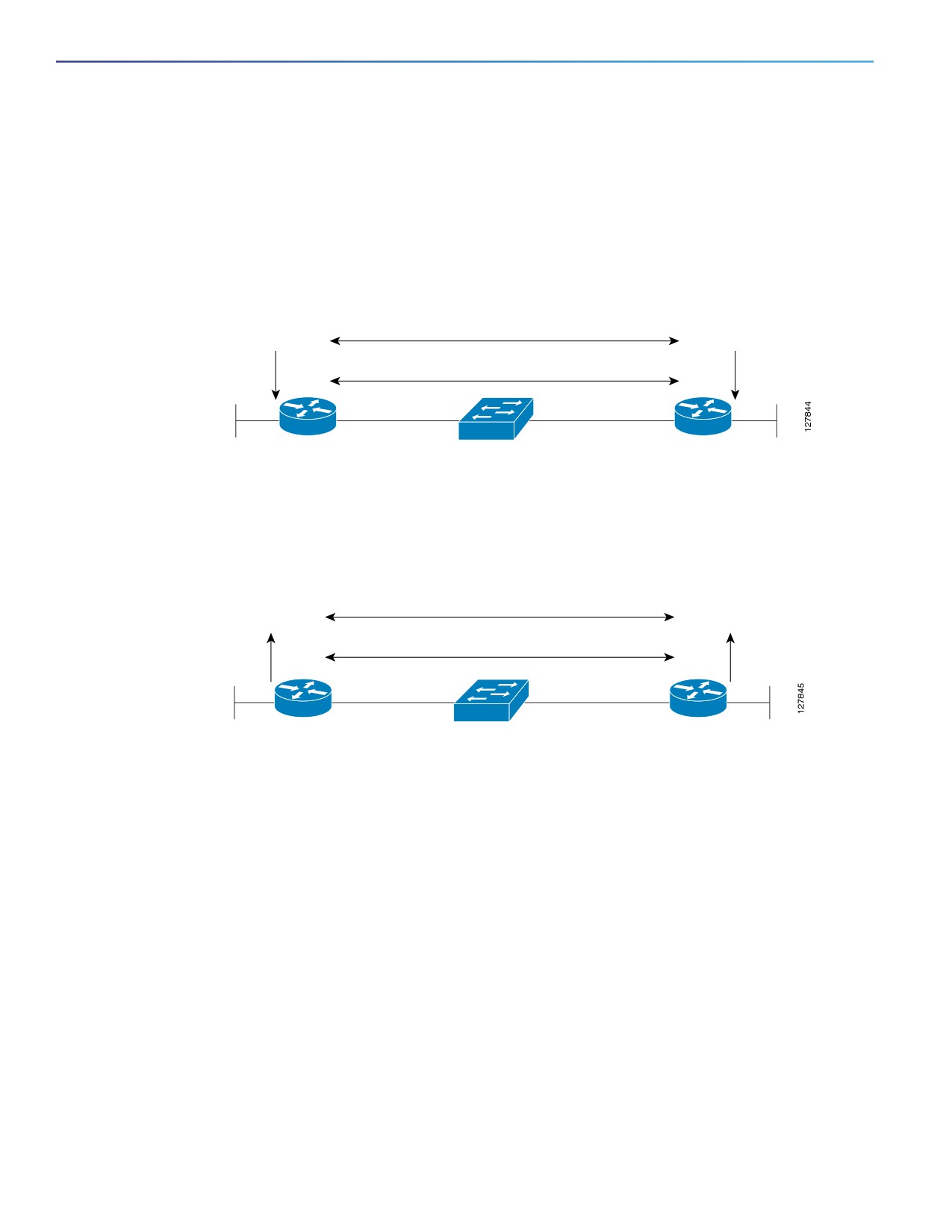
Figure 104 on page 926 shows a simple network with two routers running OSPF and BFD. When OSPF discovers a
neighbor (1), it sends a request to the BFD process to initiate a BFD neighbor session with the neighbor OSPF router (2),
establishing the BFD neighbor session (3).
Figure 104 Establishing a BFD Session
1
OSPF neighbors
OSPF
OSPF
2
2
BFD neighbors
BFD
3
BFD
172.16.10.2
172.16.10.1
Router A
Router B
172.18.0.1
172.17.0.1
Figure 105 on page 926 shows what happens when a failure occurs in the network (1). The BFD neighbor session with
the OSPF neighbor closes (2). BFD notifies the OSPF process that the BFD neighbor is no longer reachable, and the OSPF
process breaks the OSPF neighbor relationship (4). If an alternative path is available, the routers start converging on it.
Figure 105 Breaking an OSPF Neighbor Relationship
4
OSPF neighbors
X
OSPF
OSPF
3
BFD neighbors
3
X
BFD
2
BFD
1
X
172.16.10.2
172.16.10.1
172.18.0.1
Router A
Router B
172.17.0.1
BFD clients are routing protocols that register neighbors with BFD. The switch supports IS-IS, OSPF v1 and v2, BGP,
EIGRP, and HSRP clients. You can use one BFD session for multiple client protocols. For example, if a network is running
OSPF and EIGRP across the same link to the same peer, you need to create only one BFD session, and information is
shared with both routing protocols.
The switch supports BFD version 0 and version 1. BFD neighbors automatically negotiate the version and the protocol
always runs at the higher version. The default version is version 1.
By default, BFD neighbors exchange both control packets and echo packets for detecting forwarding failures. The switch
sends echo packets at the configured BFD interval rate (from 50 to 999 ms), and control packets at the BFD slow-timer
rate (from 1000 to 3000 ms).
Failure-rate detection can be faster in BFD echo mode, which is enabled by default when you configure BFD session. In
this mode, the switch sends echo packets from the BFD software layer, and the BFD neighbor responds to the echo
packets through its fast-switching layer. The echo packets do not reach the BFD neighbor software layer, but are
reflected back over the forwarding path for failure detection. You configure the rate at which each BFD interface sends
BFD echo packets by entering the bfd interval interface configuration command.
To reduce bandwidth consumption, you can disable the sending of echo packets by entering the no bfd echo interface
configuration command. When echo mode is disabled, control packets are used to detect forwarding failures. Control
packets are exchanged at the configured slow-timer rate, which could result in longer failure-detection time. You
configure this rate by entering the bfd slow-timer global configuration command. The range is from 1000 to 3000 ms;
the default rate is every 1000 ms.
926
Configuring IP Unicast Routing
Configuring BFD
You can enable or disable echo processing at a switch interface independent of the BFD neighbor configuration.
Disabling echo mode only disables the sending of echo packets by the interface. The fast-switching layer that receives
an echo packet always reflects it back to the sender.
To run BFD on a switch, you need to configure basic BFD interval parameters on BFD interfaces, enable routing on the
switch, and enable one or more one routing protocol clients for BFD. You also need to confirm that Cisco Express
Forwarding (CEF) is enabled (the default) on participating switches.
For more information on the configuration and commands, see the BFD documents listed in the Related Documents,
page 966.
This section includes the following topics:
Default BFD Configuration, page 927
Default BFD Configuration Guidelines, page 927
Configuring BFD Session Parameters on an Interface, page 928
Enabling BFD Routing Protocol Clients, page 929
Default BFD Configuration
No BFD sessions are configured. BFD is disabled on all interfaces.
When configured, BFD version 1 is the default, but switches negotiate for version. Version 0 is also supported.
Standby BFD (for HSRP) is enabled by default.
Asynchronous BFD echo mode is enabled when a BFD session is configured.
Default BFD Configuration Guidelines
The switch supports a maximum of 28 BFD sessions at one time.
To run BFD on a switch:
Configure basic BFD interval parameters on each interface over which you want to run BFD sessions.
Enable routing on the switch. You can configure BFD without enabling routing, but BFD sessions do not become
active unless routing is enabled on the switch and on the BFD interfaces.
Enable one or more one routing protocol clients for BFD. You should implement fast convergence for the routing
protocol that you are using.
Note: We recommend that you configure the BFD interval parameters on an interface before configuring the routing
protocol commands, especially when using EIGRP.
Confirm that CEF is enabled on participating switches (the default) as well as IP routing.
BFD is supported on physical interfaces that are configured as routing interfaces. It is not supported on Layer 2 interfaces,
pseudowires, static routes, SVI interfaces, or port channels.
Although you can configure BFD interface commands on a Layer 2 port, BFD sessions do not operate on the interface
unless it is configured as a Layer 3 interface (no switchport) and assigned an IP address.
In HSRP BFD, standby BFD is enabled globally by default and on all interfaces. If you disable it on an interface, you then
must disable and reenable it globally for BFD sessions to be active.
927

Configuring IP Unicast Routing
Configuring BFD
When using BFD echo mode (the default), you should disable sending of ICMP redirect messages by entering the no ip
redirects interface configuration command on the BFD interface.
Configuring BFD Session Parameters on an Interface
Before you can start a BFD session on an interface, you must put the interface into Layer 3 mode and set the baseline
BFD parameters on it.
Note: Although you can configure BFD on Layer 2 interfaces, a BFD session cannot start until both interfaces are in Layer
3 mode and routing is enabled on the switch.
BEFORE YOU BEGIN
See Default BFD Configuration Guidelines, page 927.
DETAILED STEPS
Command
Purpose
1.
configure terminal
Enter global configuration mode.
2.
interface interface-id
Specify an interface for a BFD session, and enter interface
configuration mode. Only physical interfaces support BFD.
3.
no shutdown
Enable the interface if necessary. User network interfaces (UNIs)
and enhanced network interfaces (ENIs) are disabled by default;
network node interfaces (NNIs) are enabled by default.
4.
no switchport
Remove the interface from Layer 2 configuration mode.
5.
ip address ip-address
Configure the IP address and IP subnet mask.
subnet-mask
6.
bfd interval milliseconds min_rx
Set BFD parameters for echo packets on the interface.
milliseconds multiplier value
interval—Specify the rate at which BFD echo packets are sent
to BFD peers. The range is from 50 to 999 milliseconds (ms).
min_rx—Specify the rate at which BFD echo packets are
expected to be received from BFD peers. The range is from
50 to 999 ms.
multiplier—Specify the number of consecutive BFD echo
packets that must be missed from a BFD peer before BFD
declares that it is unavailable and informs the other BFD peer
of the failure. The range is from 3 to 50.
Note: There are no baseline BFD parameter defaults.
7.
end
Return to privileged EXEC mode.
8.
show running-config
Verify your entries.
9.
show bfd neighbor detail
(Optional) Display the final configured or negotiated values when
the session is created with a neighbor.
10.
copy running-config
(Optional) Save your entries in the configuration file.
startup-config
To remove the BFD parameter configuration, enter the no bfd interval interface configuration command.
928

Configuring IP Unicast Routing
Configuring BFD
Enabling BFD Routing Protocol Clients
After you configure BFD parameters on an interface, you can start a BFD session for one or more routing protocols. You
must first enable routing by entering the ip routing global configuration command on the switch. Note that there can be
more than one way to start a BFD session on an interface, depending on the routing protocol.
Configuring BFD for OSPF, page 929
Configuring BFD for IS-IS, page 930
Configuring BFD for BGP, page 932
Configuring BFD for EIGRP, page 933
Configuring BFD for HSRP, page 934
Configuring BFD for OSPF
When you start BFD sessions for OSPF, OSPF must be running on all participating devices. You can enable BFD support
for OSPF by enabling it globally on all OSPF interfaces or by enabling it on one or more interfaces.
Configuring BFD for OSPF Globally
BEFORE YOU BEGIN
Configure BFD parameters as described in the Configuring BFD Session Parameters on an Interface, page 928.
Configure OSPF as described in the Configuring OSPF, page 865.
DETAILED STEPS
Command
Purpose
1.
configure terminal
Enter global configuration mode.
2.
router ospf process- id
Specify an OSPF process, and enter router configuration mode.
3.
bfd all-interfaces
Enable BFD globally on all interfaces associated with the OSPF
routing process.
4.
exit
(Optional) Return to global configuration mode if you want to
disable BFD on one or more OSPF interfaces.
5.
interface interface-id
(Optional) Specify an interface, and enter interface configuration
mode.
6.
ip ospf bfd disable
(Optional) Disable BFD on the specified OSPF interface. Repeat
Steps 5 and 6 for all OSPF interfaces on which you do not want to
run BFD sessions.
7.
end
Return to privileged EXEC mode.
8.
show bfd neighbors [detail]
Verify the configuration.
9.
copy running-config
(Optional) Save your entries in the configuration file.
startup-config
To disable OSPF BFD on all interfaces, enter the no bfd all-interfaces router configuration command.To disable it on an
interface, enter the no ip osfp bfd or the ip ospf bfd disable interface configuration command on the interface.
If you want to run OSPF BFD on only one or a few interfaces, you can enter the ip ospf bfd interface configuration
command on those interfaces instead of enabling it globally. See the next procedure.
929

Configuring IP Unicast Routing
Configuring BFD
Note: If you try to configure OSPF BFD on a Layer 2 interface, the configuration is not recognized.
EXAMPLE
This is an example of enabling BFD for OSPF on all OSPF interfaces:
Switch(config)# router ospf 109
Switch(config-router)# bfd all-interfaces
Switch(config-router)# exit
Configuring BFD for OSPF on an Interface
BEFORE YOU BEGIN
Configure BFD parameters on the interface as described in the Configuring BFD Session Parameters on an Interface,
page 928.
Configure OSPF as described in the Configuring OSPF, page 865.
DETAILED STEPS
Command
Purpose
1.
configure terminal
Enter global configuration mode.
2.
router ospf process- id
Specify an OSPF process, and enter router configuration mode.
3.
exit
Return to global configuration mode.
4.
interface interface-id
Specify an interface, and enter interface configuration mode.
5.
ip ospf bfd
Enable BFD on the specified OSPF interface. Repeat Steps 3 and
4 for all OSPF interfaces on which you want to run BFD sessions.
6.
end
Return to privileged EXEC mode.
7.
show bfd neighbors [detail]
Verify the configuration.
8.
copy running-config
(Optional) Save your entries in the configuration file.
startup-config
To disable OSPF BFD on an interface, enter the no ip osfp bfd or the ip ospf bfd disable interface configuration
command on the interface.
EXAMPLE
This is an example of enabling BFD for OSPF on a single interface:
Switch(config)# router ospf 109
Switch(config-router)# exit
Switch(config)# interface gigabitethernet0/1
Switch(config-if)# ip ospf bfd
Configuring BFD for IS-IS
When you start BFD sessions for IS-IS, IS-IS must be running on all devices participating in BFD. You can enable BFD
support for IS-IS by enabling it globally on all IS-IS interfaces or by enabling it on one or more interfaces.
Configuring BFD for IS-IS Globally
BEFORE YOU BEGIN
Configure BFD parameters on the interface as described in the Configuring BFD Session Parameters on an Interface,
page 928.
930

Configuring IP Unicast Routing
Configuring BFD
Configure IS-IS as described in the Configuring IS-IS Dynamic Routing, page 913.
DETAILED STEPS
Command
Purpose
1.
configure terminal
Enter global configuration mode.
2.
router is-is area-tag
Specify an IS-IS process and enter router configuration mode.
3.
bfd all-interfaces
Enable BFD globally on all interfaces associated with the IS-IS
routing process.
4.
exit
(Optional) Return to global configuration mode if you want to
disable BFD on one or more IS-IS interfaces.
5.
interface interface-id
(Optional) Specify an interface and enter interface configuration
mode.
6.
ip router isis
(Optional) Enable IPv4 IS-IS routing on the interface.
7.
isis bfd disable
(Optional) Disable BFD on the IS-IS interface. Repeat Steps 5
through 7 for all IS-IS interfaces on which you do not want to run
BFD sessions.
8.
end
Return to privileged EXEC mode.
9.
show bfd neighbors [detail]
Verify the configuration.
10.
copy running-config
(Optional) Save your entries in the configuration file.
startup-config
To disable IS-IS BFD on all interfaces, enter the no bfd all-interfaces router configuration command. To disable it on the
specified interface, enter the no isis bfd or the isis bfd disable interface configuration command on the interface.
If you only want to run IS-IS BFD on a few interfaces, instead of enabling it globally, you can enter the isis bfd interface
configuration command on those interfaces. See the next procedure.
Note: Although IS-IS BFD operates only on Layer 3 interfaces, you can configure it on interfaces in Layer 2 or Layer 3
mode. When you enable it, you see this message:
%ISIS BFD is reverting to router mode configuration, and remains disabled.
EXAMPLE
This is an example of setting fast convergence and enabling BFD for IS-IS on all IS-IS interfaces:
Switch(config)# router is-is tag1
Switch(config-router)# bfd all-interfaces
Switch(config-router)# exit
Configuring BFD for IS-IS on an Interface
BEFORE YOU BEGIN
Configure BFD parameters on the interface as described in the Configuring BFD Session Parameters on an Interface,
page 928.
Configure IS-IS as described in the Configuring IS-IS Dynamic Routing, page 913.
931

Configuring IP Unicast Routing
Configuring BFD
DETAILED STEPS
Command
Purpose
1.
configure terminal
Enter global configuration mode.
2.
router is-is area-tag
Specify an IS-IS process and enter router configuration mode.
3.
exit
Return to global configuration mode.
4.
interface interface-id
Specify an interface, and enter interface configuration mode.
5.
isis bfd
Enable BFD on the specified IS-IS interface. Repeat Steps 3 and
4 for all IS-IS interfaces on which you want to run BFD sessions.
6.
end
Return to privileged EXEC mode.
7.
show bfd neighbors [detail]
Verify the configuration.
8.
copy running-config
(Optional) Save your entries in the configuration file.
startup-config
To disable IS-IS BFD on an interface, enter the no isis bfd or the isis bfd disable interface configuration command on
the interface.
EXAMPLE
This is an example of enabling BFD for IS-IS on a single interface:
Switch(config)# router is-is tag1
Switch(config-router)# exit
Switch(config)# interface gigabitethernet0/1
Switch(config-if)# isis bfd
Configuring BFD for BGP
When you start BFD sessions for BGP, BGP must be running on all participating devices. You enter the IP address of the
BFD neighbor to enable BFD for BGP.
BEFORE YOU BEGIN
Configure BFD parameters on the interface as described in the Configuring BFD Session Parameters on an Interface,
page 928.
Configure BGP as described in the Configuring BGP, page 888.
932

Configuring IP Unicast Routing
Configuring BFD
DETAILED STEPS
Command
Purpose
1.
configure terminal
Enter global configuration mode.
2.
router bgp as-tag
Specify a BGP autonomous system, and enter router configuration
mode.
3.
neighbor ip-address fall-over
Enable BFD support for fallover on the BFD neighbor.
bfd
4.
end
Return to privileged EXEC mode.
5.
show bfd neighbors [detail]
Verify the configuration.
>
show ip bgp neighbor
Display information about BGP connections to neighbors.
6.
copy running-config
(Optional) Save your entries in the configuration file.
startup-config
To disable BGP BFD, enter the no neighbor ip-address fall-over bfd router configuration command.
Configuring BFD for EIGRP
When you start BFD sessions for EIGRP, EIGRP must be running on all participating devices.You can enable BFD support
for EIGRP by globally enabling it on all EIGRP interfaces or by enabling it on one or more interfaces.
BEFORE YOU BEGIN
Configure BFD parameters on the interface as described in the Configuring BFD Session Parameters on an Interface,
page 928.
Configure EIGRP as described in the Configuring EIGRP, page 880.
933

Configuring IP Unicast Routing
Configuring BFD
DETAILED STEPS
Command
Purpose
1.
configure terminal
Enter global configuration mode.
2.
router eigrp as-number
Specify an EIGRP autonomous system number, and enter router
configuration mode.
3.
log-adjacency changes [detail]
Configure the switch to send a system logging message when an
EIGRP neighbor goes up or down.
4.
bfd {all-interfaces | interface
Enable BFD for EIGRP.
interface-id}
Enter all-interfaces to globally enable BFD on all interfaces
associated with the EIGRP routing process.
Enter interface interface-id to enable BFD on a per-interface
basis for one or more interfaces associated with the EIGRP
routing process.
5.
end
Return to privileged EXEC mode.
6.
show bfd neighbors [detail]
Verify the configuration.
7.
copy running-config
(Optional) Save your entries in the configuration file.
startup-config
To disable EIGRP BFD on all interfaces, enter the no bfd all-interfaces router configuration command. To disable it on
an interface, enter the no bfd interface interface-id router configuration command.
Configuring BFD for HSRP
HSRP supports BFD by default; it is globally enabled on all interfaces. If HSRP support has been manually disabled, you
can reenable it in interface or global configuration mode.
BEFORE YOU BEGIN
Configure BFD parameters on the interface as described in the Configuring BFD Session Parameters on an Interface,
page 928.
Ensure that all participating devices have HSRP enabled and CEF enabled (the default).
934

Configuring IP Unicast Routing
Configuring BFD
DETAILED STEPS
Command
Purpose
1.
configure terminal
Enter global configuration mode.
2.
interface interface-id
Specify an interface for a BFD session, and enter interface
configuration mode. Only physical interfaces support BFD.
3.
ip address ip-address
Configure the IP address and IP subnet mask for the interface.
subnet-mask
4.
standby [group-number] ip
Activate HSRP.
[ip-address] [secondary]]
5.
standby bfd
(Optional) Enable HSRP support for BFD on the interface.
6.
exit
Return to global configuration mode.
7.
standby bfd all-interfaces
(Optional) Enable HSRP support for BFD on all interfaces.
8.
end
Return to privileged EXEC mode.
9.
show standby neighbors
Verify your entries.
10.
copy running-config
(Optional) Save your entries in the configuration file.
startup-config
To disable HSRP support for BFD on all interfaces, enter the no standby bfd all-interfaces global configuration
command. To disable it on an interface, enter the no standby bfd interface configuration command.
Note: If you disable standby BFD on an interface by entering the no standby bfd interface configuration command, to
activate BFD sessions on other interfaces, you must disable and reenable it globally by entering the no standby bfd
all-interfaces global configuration command followed by the standby bfd all-interfaces global configuration command.
EXAMPLE
The following example shows how to reenable HSRP BFD peering if it has been disabled on a switch:
Switch(config)# standby bfd all-interfaces
Disabling BFD Echo Mode
When you configure a BFD session, BFD echo mode is enabled by default on BFD interfaces. You can disable echo mode
on an interface so it sends no echo packets and but only sends back echo packets received from a neighbor. When echo
mode is disabled, control packets are used to detect forwarding failures. You can configure slow timers to reduce the
frequency of BFD control packets.
BEFORE YOU BEGIN
Configure BFD parameters on the interface as described in the Configuring BFD Session Parameters on an Interface,
page 928.
935

Configuring IP Unicast Routing
Configuring Multi-VRF CE
DETAILED STEPS
Command
Purpose
1.
configure terminal
Enter global configuration mode.
2.
interface interface-id
Enter a BFD interface and enter interface configuration mode.
3.
no bfd echo
Disable BFD echo mode on the interface. It is enabled by default,
but can be disabled independently on BFD neighbors.
4.
exit
Return to global configuration mode.
5.
bfd slow-timer [milliseconds]
(Optional) Configure a BFD slow-timer value. The range is from
1000 to 30000 milliseconds. The default is 1000 milliseconds.
6.
end
Return to privileged EXEC mode.
7.
show bfd neighbors detail
Verify your entries.
8.
copy running-config
(Optional) Save your entries in the configuration file.
startup-config
To reenable echo mode on the switch, enter the bfd echo global configuration command.
EXAMPLE
The following example disables echo mode between BFD neighbors:
Switch# configure terminal
Switch(config)# interface Ethernet 0/1
Switch(config-if)# no bfd echo
Configuring Multi-VRF CE
Virtual Private Networks (VPNs) provide a secure way for customers to share bandwidth over an ISP backbone network.
A VPN is a collection of sites sharing a common routing table. A customer site is connected to the service-provider
network by one or more interfaces, and the service provider associates each interface with a VPN routing table, called a
VPN routing/forwarding (VRF) table.
The switch supports multiple VPN routing/forwarding (multi-VRF) instances in customer edge (CE) devices (multi-VRF
CE). With multi-VRF CE, a service provider can support two or more VPNs with overlapping IP addresses.
Note: The switch does not use Multiprotocol Label Switching (MPLS) to support VPNs. For information about MPLS VRF,
refer to the MPLS: Layer 3 VPNs Configuration Guide, Cisco IOS Release 15M&T.
Information About Multi-VRF CE, page 937
Default Multi-VRF CE Configuration, page 938
Multi-VRF CE Configuration Guidelines, page 938
Configuring VRFs, page 939
Configuring VRF-Aware Services, page 940
Configuring a VPN Routing Session, page 945
Configuring BGP PE to CE Routing Sessions, page 946
Displaying Multi-VRF CE Status, page 947
936