Cisco Industrial Ethernet 4000, 4010 and 5000 Switch Software. Configuration Guide (2022) - page 30
Chapter Configuring HSRP and VRRP
Configuring HSRP
Use the no standby [group-number] priority priority [preempt [delay delay]] and no standby
[group-number] [priority priority] preempt [delay delay] interface configuration commands to restore
default priority, preempt, and delay values.
Use the no standby [group-number] track type number [interface-priority] interface configuration
command to remove the tracking.
This example activates a port, sets an IP address and a priority of 120 (higher than the default value),
and waits for 300 seconds (5 minutes) before attempting to become the active router:
Switch# configure terminal
Switch(config)# interface gigabitethernet1/1
Switch(config-if)# no switchport
Switch(config-if)# standby ip 172.20.128.3
Switch(config-if)# standby priority 120 preempt delay 300
Switch(config-if)# end
Configuring MHSRP
To enable MHSRP and load balancing, you configure two routers as active routers for their groups, with
virtual routers as standby routers. This example shows how to enable the MHSRP configuration shown
in Figure 49-97. You need to enter the standby preempt interface configuration command on each
HSRP interface so that if a router fails and comes back up, the preemption occurs and restores load
balancing.
Router A is configured as the active router for group 1, and Router B is configured as the active router
for group 2. The HSRP interface for Router A has an IP address of 10.0.0.1 with a group 1 standby
priority of 110 (the default is 100). The HSRP interface for Router B has an IP address of 10.0.0.2 with
a group 2 standby priority of 110.
Group 1 uses a virtual IP address of 10.0.0.3 and group 2 uses a virtual IP address of 10.0.0.4.
Router A Configuration
Switch# configure terminal
Switch(config)# interface gigabitethernet1/1
Switch(config-if)# no switchport
Switch(config-if)# ip address 10.0.0.1 255.255.255.0
Switch(config-if)# standby 1 ip 10.0.0.3
Switch(config-if)# standby 1 priority 110
Switch(config-if)# standby 1 preempt
Switch(config-if)# standby 2 ip 10.0.0.4
Switch(config-if)# standby 2 preempt
Switch(config-if)# end
Router B Configuration
Switch# configure terminal
Switch(config)# interface gigabitethernet1/1
Switch(config-if)# no switchport
Switch(config-if)# ip address 10.0.0.2 255.255.255.0
Switch(config-if)# standby 1 ip 10.0.0.3
Switch(config-if)# standby 1 preempt
Switch(config-if)# standby 2 ip 10.0.0.4
Switch(config-if)# standby 2 priority 110
Switch(config-if)# standby 2 preempt
Switch(config-if)# end
Cisco Industrial Ethernet 4000 Series Switch Software Configuration Guide
-817

Chapter
Configuring HSRP and VRRP
Configuring HSRP
Configuring HSRP Authentication and Timers
You can optionally configure an HSRP authentication string or change the hello-time interval and
holdtime.
When configuring these attributes, follow these guidelines:
• The authentication string is sent unencrypted in all HSRP messages. You must configure the same
authentication string on all routers and access servers on a cable to ensure interoperation.
Authentication mismatch prevents a device from learning the designated Hot Standby IP address and
timer values from other routers configured with HSRP.
• Routers or access servers on which standby timer values are not configured can learn timer values
from the active or standby router. The timers configured on an active router always override any
other timer settings.
• All routers in a Hot Standby group should use the same timer values. Normally, the holdtime is
greater than or equal to 3 times the hellotime.
Beginning in privileged EXEC mode, use one or more of these steps to configure HSRP authentication
and timers on an interface:
Command
Purpose
Step
1
configure terminal
Enter global configuration mode.
Step
2
interface interface-id
Enter interface configuration mode, and enter the HSRP
interface on which you want to set authentication.
Step
3
standby [group-number] authentication string
(Optional) authentication string—Enter a string to be carried in
all HSRP messages. The authentication string can be up to eight
characters in length; the default string is cisco.
(Optional) group-number—The group number to which the
command applies.
Step
4
standby [group-number] timers hellotime
(Optional) Configure the time between hello packets and the
holdtime
time before other routers declare the active router to be down.
• group-number—The group number to which the command
applies.
• hellotime—The hello interval in seconds. The range is from
1 to 255; the default is 3 seconds.
• holdtime—The time in seconds before the active or standby
router is declared to be down. The range is from 1 to 255;
the default is 10 seconds.
Step
5
end
Return to privileged EXEC mode.
Step
6
show running-config
Verify the configuration of the standby groups.
Step
7
copy running-config startup-config
(Optional) Save your entries in the configuration file.
Use the no standby [group-number] authentication string interface configuration command to delete
an authentication string. Use the no standby [group-number] timers hellotime holdtime interface
configuration command to restore timers to their default values.
This example shows how to configure word as the authentication string required to allow Hot Standby
routers in group 1 to interoperate:
Cisco Industrial Ethernet 4000 Series Switch Software Configuration Guide
-818
Chapter Configuring HSRP and VRRP
Configuring HSRP
Switch# configure terminal
Switch(config)# interface gigabitethernet1/1
Switch(config-if)# no switchport
Switch(config-if)# standby 1 authentication word
Switch(config-if)# end
This example shows how to set the timers on standby group 1 with the time between hello packets at 5
seconds and the time after which a router is considered down to be 15 seconds:
Switch# configure terminal
Switch(config)# interface gigabitethernet1/1
Switch(config-if)# no switchport
Switch(config-if)# standby 1 ip
Switch(config-if)# standby 1 timers 5 15
Switch(config-if)# end
Enabling HSRP Support for ICMP Redirect Messages
The Internet Control Message Protocol (ICMP) is a network layer Internet protocol that provides
message packets to report errors and other information relevant to IP processing. ICMP provides
diagnostic functions, such as sending and directing error packets to the host.
When the switch is running HSRP, make sure hosts do not discover the interface (or real) MAC addresses
of routers in the HSRP group. If a host is redirected by ICMP to the real MAC address of a router and
that router later fails, packets from the host will be lost.
ICMP redirect messages are automatically enabled on interfaces configured with HSRP. This feature
filters outgoing ICMP redirect messages through HSRP, in which the next hop IP address might be
changed to an HSRP virtual IP address.
Configuring HSRP Groups and Clustering
When a device is participating in an HSRP standby routing and clustering is enabled, you can use the
same standby group for command switch redundancy and HSRP redundancy. Use the cluster
standby-group HSRP-group-name [routing-redundancy] global configuration command to enable the
same HSRP standby group to be used for command switch and routing redundancy. If you create a
cluster with the same HSRP standby group name without entering the routing-redundancy keyword,
HSRP standby routing is disabled for the group.
This example shows how to bind standby group my_hsrp to the cluster and enable the same HSRP group
to be used for command switch redundancy and router redundancy. The command can only be executed
on the cluster command switch. If the standby group name or number does not exist, or if the switch is
a cluster member switch, an error message appears.
Switch# configure terminal
Switch(config)# cluster standby-group my_hsrp routing-redundancy
Switch(config)# end
Troubleshooting HSRP
If one of the situations in Table 49-64 occurs, this message appears:
%FHRP group not consistent with already configured groups on the switch stack -
virtual MAC reservation failed
Cisco Industrial Ethernet 4000 Series Switch Software Configuration Guide
-819

Chapter
Configuring HSRP and VRRP
Displaying HSRP Configurations
Table 49-64
Troubleshooting HSRP
Situation
Action
You configure more than 32 HSRP group
Remove HSRP groups so that up to 32 group
instances.
instances are configured.
You configure HSRP for IPv4 and HSRP for IPv6
Configure either HSRP for IPv4 or HSRP for IPv6
at the same time
on the switch.
You configure group numbers that are not in valid
Configure group numbers in a valid range.
ranges of 256.
Displaying HSRP Configurations
From privileged EXEC mode, use this command to display HSRP settings:
show standby [interface-id [group]] [brief] [detail]
You can display HSRP information for the whole switch, for a specific interface, for an HSRP group, or
for an HSRP group on an interface. You can also specify whether to display a concise overview of HSRP
information or detailed HSRP information. The default display is detail. If there are a large number of
HSRP groups, using the show standby command without qualifiers can result in an unwieldy display.
This is a an example of output from the show standby privileged EXEC command, displaying HSRP
information for two standby groups (group 1 and group 100):
Switch# show standby
VLAN1 - Group 1
Local state is Standby, priority 105, may preempt
Hellotime 3 holdtime 10
Next hello sent in 00:00:02.182
Hot standby IP address is 172.20.128.3 configured
Active router is 172.20.128.1 expires in 00:00:09
Standby router is local
Standby virtual mac address is 0000.0c07.ac01
Name is bbb
VLAN1 - Group 100
Local state is Active, priority 105, may preempt
Hellotime 3 holdtime 10
Next hello sent in 00:00:02.262
Hot standby IP address is 172.20.138.51 configured
Active router is local
Standby router is unknown expired
Standby virtual mac address is 0000.0c07.ac64
Name is test
Configuring VRRP
The Virtual Router Redundancy Protocol (VRRP) is an election protocol that dynamically assigns
responsibility for one or more virtual routers to the VRRP routers on a LAN, allowing several routers
on a multiaccess link to utilize the same virtual IP address. A VRRP router is configured to run the VRRP
protocol in conjunction with one or more other routers attached to a LAN. In a VRRP configuration, one
router is elected as the virtual router master, with the other routers acting as backups in case the virtual
router master fails.
Cisco Industrial Ethernet 4000 Series Switch Software Configuration Guide
-820
Chapter Configuring HSRP and VRRP
Configuring VRRP
VRRP Limitations
• The switch supports either HSRP or VRRP, but not both. The switch cannot join a stack that has both
HSRP and VRRP configured.
• The VRRP implementation on the switch does not support the MIB specified in RFC 2787.
• The VRRP implementation on the switch supports only text-based authentication.
• You cannot enable VRRP for IPv4 and IPv6 groups simultaneously.
Cisco Industrial Ethernet 4000 Series Switch Software Configuration Guide
-821
Chapter
Configuring HSRP and VRRP
Configuring VRRP
Cisco Industrial Ethernet 4000 Series Switch Software Configuration Guide
-822
Configuring IPv6 ACLs
This chapter provides details about configuring IPv6 access control lists (ACLs) on the Cisco Industrial Ethernet Switches,
hereafter referred to as switch.
When the switch is running the IP services image:
You can filter IPv6 traffic by creating IPv6 ACLs and applying them to interfaces
You can create and apply input router ACLs to filter Layer 3 management traffic
This chapter contains the following sections:
Information About IPv6 ACLs, page 823
Prerequisites, page 824
Guidelines and Limitations, page 824
Default Settings, page 825
Configuring IPv6 ACLs, page 825
Verifying IPv6 ACLs, page 829
Configuration Example, page 830
Information About IPv6 ACLs
A switch running the IP services image supports two types of IPv6 ACLs:
IPv6 router ACLs on outbound or inbound traffic on Layer 3 interfaces only, which can be routed ports, switch virtual
interfaces (SVIs), or Layer 3 EtherChannels.
IPv6 router ACLs apply only to routed IPv6 packets.
IPv6 port ACLs on inbound traffic on Layer 2 interfaces only. The switch applies IPv6 port ACLs to all IPv6 packets
entering the interface.
You can apply both IPv4 and IPv6 ACLs to an interface.
As with IPv4 ACLs, IPv6 port ACLs take precedence over router ACLs:
When an input router ACL and input port ACL exist in an SVI, packets received on ports to which a port ACL is applied
are filtered by the port ACL. Routed IP packets received on other ports are filtered by the router ACL. Other packets
are not filtered.
When an output router ACL and input port ACL exist in an SVI, packets received on the ports to which a port ACL is
applied are filtered by the port ACL. Outgoing routed IPv6 packets are filtered by the router ACL. Other packets are
not filtered.
Note: When you apply any port ACL (IPv4, IPv6, or MAC) to an interface, that port ACL filters packets, and ignores any
router ACLs attached to the SVI of the port VLAN.
823
Configuring IPv6 ACLs
Prerequisites
Supported ACL Features
IPv6 ACLs on the switch have these characteristics:
Fragmented frames (the fragments keyword as in IPv4) are supported.
The same statistics supported in IPv4 are supported for IPv6 ACLs.
If the switch runs out of hardware space, packets associated with the ACL are forwarded to the CPU, and the
software applies the ACLs.
Routed or bridged packets with hop-by-hop options have IPv6 ACLs applied in software.
Logging is supported for router ACLs, but not for port ACLs.
The switch supports IPv6 address-matching for a full range of prefix-lengths.
Note: For items not supported for IPv6 ACLS, see Guidelines and Limitations, page 824.
Prerequisites
Be sure to review Guidelines and Limitations, page 824 and the Before You Begin section within each configuration
section before configuring a feature.
Guidelines and Limitations
ACLs for IPv6 Traffic Not Supported
The switch does not support VLAN ACLs (VLAN maps) for IPv6 traffic.
The switch does not apply MAC-based ACLs on IPv6 frames.
You cannot apply IPv6 port ACLs to Layer 2 EtherChannels.
The switch does not support output port ACLs.
Cisco IOS IPv6 ACLs Functions Not Supported
The switch does not support matching on these keywords: flowlabel, routing header, and
undetermined-transport.
The switch does not support reflexive ACLs (the reflect keyword).
Access Control Entry (ACE) and ACLs
When you apply an ACL to an interface and you attempt to add an access control entry (ACE) with an unsupported
keyword, the switch does not allow the ACE to be added to the attached ACL.
Named ACLs
IPv6 supports only named ACLs.
IPv6 ACLs Interactions With Other Switches or Features
When you configure an IPv6 router ACL to deny a packet, the software does not route the packet. Instead, the
software forwards a copy of the packet to the Internet Control Message Protocol (ICMP) queue to generate an ICMP
unreachable message for the frame.
If a bridged frame is to be dropped due to a port ACL, the frame is not bridged.
824
Configuring IPv6 ACLs
Default Settings
You can create both IPv4 and IPv6 ACLs on a switch, and you can apply both IPv4 and IPv6 ACLs to the same
interface.
— Each ACL must have a unique name; and, an error message appears if you try to use a name that already exists
on the switch.
— You use different commands to create IPv4 and IPv6 ACLs and to attach IPv4 or IPv6 ACLs to the same Layer 2
or Layer 3 interface.
If you use the wrong command to attach an ACL (for example, an IPv4 command to attach an IPv6 ACL), you
receive an error message.
You cannot use MAC ACLs to filter IPv6 frames. MAC ACLs can only filter non-IP frames.
If the hardware memory is full, for any additional configured ACLs, the switch forwards the packets to the CPU, and
the software applies the ACLs.
Default Settings
Parameters
Default
IPv6 ACLs
There are no default IPv6 ACLs configured or applied on
the switch.
Configuring IPv6 ACLs
This section includes the following topics:
Creating IPv6 ACLs, page 825
Applying an IPv6 ACL to an Interface, page 829
BEFORE YOU BEGIN
Review the Guidelines and Limitations, page 824 for this feature.
Select one of the dual IPv4 and IPv6 SDM templates.
Creating IPv6 ACLs
Note: When you configure an unsupported IPv6 ACL, an error message appears, and the configuration does not take
affect.
Use the no {deny | permit} IPv6 access-list configuration commands with keywords to remove the deny or permit
conditions from the specified access list for the commands below.
825

Configuring IPv6 ACLs
Configuring IPv6 ACLs
DETAILED STEPS
Command
Purpose
1.
configure terminal
Enter global configuration mode.
2.
ipv6 access-list access-list-name
Define an IPv6 access list using a name, and enter IPv6
access-list configuration mode.
3.
a
{deny | permit} protocol
Deny or permit the packet, when specified conditions are
{source-ipv6-prefix/prefix-length | any |
matched. These are the conditions:
host source-ipv6-address} [operator
[port-number]] {destination-ipv6-prefix/
protocol-Name or number of an Internet protocol:
ahp, esp, icmp, ipv6, pcp, stcp, tcp, or udp, or an
prefix-length | any |
host destination-ipv6-address}
integer in the range 0 to 255 representing an IPv6
[operator [port-number]]
protocol number. For additional specific parameters
for ICMP, TCP, and UDP, see Steps 3b through 3d.
[dscp value] [fragments] [log]
[log-input] [routing] [sequence value]
source-ipv6-prefix/prefix-length or
[time-range name]
destination-ipv6-prefix/ prefix-length-Source or
destination IPv6 network or class of networks for
which to set deny or permit conditions, specified in
hexadecimal and using 16-bit values between colons.
Enter any as an abbreviation for the IPv6 prefix ::/0.
host source-ipv6-address or
destination-ipv6-address- Define source or
destination IPv6 host address for which to set deny or
permit conditions, specified in hexadecimal and using
16-bit values between colons.
(Optional) operator-Operand that compares the
source or destination ports of the specified protocol
such as
lt (less than), gt (greater than), eq (equal), neq (not
equal), and range.
If the operator follows the
source-ipv6-prefix/prefix-length argument, it must
match the source port. If the operator follows the
destination-ipv6- prefix/prefix-length argument, it
must match the destination port.
826

Configuring IPv6 ACLs
Configuring IPv6 ACLs
Command
Purpose
(Optional) port-number- Value of 0 to 65535 or TCP
or UDP port name. Use TCP port names only when
filtering TCP. Use UDP port names only when filtering
UDP.
(Optional) dscp value-Match a differentiated services
code point value against the traffic class value in the
Traffic Class field of each IPv6 packet header. The
acceptable range is from 0 to 63.
(Optional) fragments-Check noninitial fragments.
Keyword is only visible when the protocol is ipv6.
(Optional, router ACLs only) log-Send a logging
message to the console about the packet that
matches the entry. Enter log-input to include the
input interface in the log entry.
(Optional) routing-Specify routing of IPv6 packets.
(Optional) sequence value-Specify the sequence
number for the access list statement. Value range is
from 1 to 4294967295.
(Optional) time-range name-Specify the time range
that applies to the deny or permit statement.
Step
{deny | permit} tcp
(Optional) Define a TCP access list and the access
3b
{source-ipv6-prefix/prefix-length | any |
conditions.
host source-ipv6-address} [operator
Enter tcp for Transmission Control Protocol. The
[port-number]] {destination-ipv6-
prefix/prefix-length | any | host
parameters are the same as those described in Step 3a,
destination-ipv6-address} [operator
with these additional optional parameters:
[port-number]] [ack] [dscp value]
ack—Acknowledgment bit set.
[established] [fin] [log] [log-input] [neq
{port | protocol}] [psh] [range {port |
established—An established connection. A match
protocol}] [rst] [routing] [sequence
occurs if the TCP datagram has the ACK or RST bits
value] [syn] [time-range name] [urg]
set.
fin—Finished bit set; no more data from sender.
neq {port | protocol}—Match only packets that are not
on a given port number.
psh—Push function bit set.
range {port | protocol}—Match only packets in the port
number range.
rst—Reset bit set.
syn—Synchronize bit set.
urg—Urgent pointer bit set.
827

Configuring IPv6 ACLs
Configuring IPv6 ACLs
Command
Purpose
Step
{deny | permit} udp
(Optional) Define a UDP access list and the access
3c
{source-ipv6-prefix/prefix-length | any |
conditions.
host source-ipv6-address} [operator
[port-number]]
Enter udp for the User Datagram Protocol. The UDP
{destination-ipv6-prefix/prefix-length |
parameters are the same as those described for TCP,
any | host destination-ipv6-address}
except that the [operator [port]] port number or name
[operator [port-number]] [dscp value]
must be a UDP port number or name, and the established
[log] [log-input] [neq {port | protocol}]
parameter is not valid for UDP.
[range {port | protocol}] [routing]
[sequence value] [time-range name]
Step
{deny | permit} icmp
(Optional) Define an ICMP access list and the access
3d
{source-ipv6-prefix/prefix-length | any |
conditions.
host source-ipv6-address} [operator
[port-number]]
Enter icmp for Internet Control Message Protocol. The
ICMP parameters are the same as those described for
{destination-ipv6-prefix/prefix-length |
any | host destination-ipv6-address}
most IP protocols in Step 3a, with the addition of the ICMP
[operator [port-number]] [icmp-type
message type and code parameters. These optional
keywords have these meanings:
[icmp-code] | icmp-message] [dscp
value] [log] [log-input] [routing]
icmp-type—Enter to filter by ICMP message type, a
[sequence value] [time-range name]
number from 0 to 255.
icmp-code—Enter to filter ICMP packets that are
filtered by the ICMP message code type, a number
from 0 to 255.
icmp-message—Enter to filter ICMP packets by the
ICMP message type name or the ICMP message type
and code name. To see a list of ICMP message type
names and code names, use the ? key.
4.
end
Return to privileged EXEC mode.
5.
show ipv6 access-list
Verify the access list configuration.
6.
copy running-config startup-config
(Optional) Save your entries in the configuration file.
EXAMPLE
The following example:
Creates an IPv6 ACL named CISCO.
Defines one deny entry that denies all packets that have a destination TCP port number greater than 5000 and a
second deny entry that denies packets that have a source UDP port number less than 5000. The second deny entry
also logs all matches to the console.
Defines a permit entry to permit all ICMP packets and another permit entry that allows all other traffic. The second
permit entry is necessary because an implicit deny-all condition is at the end of each IPv6 access list.
Switch(config)# ipv6 access-list CISCO
Switch(config-ipv6-acl)# deny tcp any any gt 5000
Switch config-ipv6-acl)# deny ::/0 lt 5000 ::/0 log
Switch(config-ipv6-acl)# permit icmp any any
Switch(config-ipv6-acl)# permit any any
828

Configuring IPv6 ACLs
Verifying IPv6 ACLs
Applying an IPv6 ACL to an Interface
BEFORE YOU BEGIN
Review the Guidelines and Limitations, page 824 for this feature.
DETAILED STEPS
Command
Purpose
1.
configure terminal
Enter global configuration mode.
2.
interface interface-id
Identify a Layer 2 interface (for port ACLs) or Layer 3
interface (for router ACLs) on which to apply an access list,
and enter interface configuration mode.
3.
no switchport
If applying a router ACL, change the interface from Layer 2
mode (the default) to Layer 3 mode.
4.
ipv6 address ipv6-address
Configure an IPv6 address on a Layer 3 interface (for router
ACLs).
Note: This command is not required on Layer 2 interfaces
or if the interface is already configured with an explicit IPv6
address.
Use the no ipv6 traffic-filter access-list-name interface
configuration command to remove an access list from an
interface.
5.
ipv6 traffic-filter access-list-name {in |
Apply the access list to incoming or outgoing traffic on the
out}
interface.
Note: The out keyword is not supported for Layer 2
interfaces (port ACLs).
6.
end
Return to privileged EXEC mode.
7.
show running-config
Verify the access list configuration.
8.
copy running-config startup-config
(Optional) Save your entries in the configuration file.
EXAMPLE
This example shows how to apply the access list CISCO to outbound traffic on a Layer 3 interface:
Switch(config)# interface gigabitethernet 0/3
Switch(config-if)# no switchport
Switch(config-if)# ipv6 address 2001::/64 eui-64
Switch(config-if)# ipv6 traffic-filter CISCO out
Verifying IPv6 ACLs
You can display information about all configured access lists, all IPv6 access lists, or a specific access list by using one
or more of the following privileged EXEC commands.
829
Configuring IPv6 ACLs
Configuration Example
Command
Purpose
show access-lists
Display all access lists configured on the switch.
show ipv6 access-list [access-list-name]
Display all configured IPv6 access list or the access list specified by
name.
Configuration Example
The following example:
Creates an IPv6 ACL named CISCO.
Defines one deny entry that denies all packets that have a destination TCP port number greater than 5000 and a
second deny entry that denies packets that have a source UDP port number less than 5000. The second deny entry
also logs all matches to the console.
Defines a permit entry to permit all ICMP packets and another permit entry that allows all other traffic. The second
permit entry is necessary because an implicit deny-all condition is at the end of each IPv6 access list.
Applies the access list CISCO to outbound traffic on a Layer 3 interface.
Switch(config)# ipv6 access-list CISCO
Switch(config-ipv6-acl)# deny tcp any any gt 5000
Switch config-ipv6-acl)# deny ::/0 lt 5000 ::/0 log
Switch(config-ipv6-acl)# permit icmp any any
Switch(config-ipv6-acl)# permit any any
Switch(config-ipv6-acl)# exit
Switch(config)# interface gigabitethernet 0/3
Switch(config-if)# no switchport
Switch(config-if)# ipv6 address 2001::/64 eui-64
Switch(config-if)# ipv6 traffic-filter CISCO out
830
Configuring Embedded Event Manager
Embedded Event Manager (EEM) is a distributed and customized approach to event detection and recovery within a Cisco
IOS device. EEM offers the ability to monitor events and take informational, corrective, or any other EEM action when the
monitored events occur or when a threshold is reached. An EEM policy defines an event and the actions to be taken when
that event occurs.
This chapter describes how to configure EEM and how to use it to monitor and manage the Cisco Industrial Ethernet
Switches, hereafter referred to as switch.
Note: For complete syntax and usage information for the commands used in this chapter, see the documents listed in
the Related Documents, page 838.
This chapter includes these sections:
Information About Embedded Event Manager, page 831
Prerequisites, page 835
Guidelines and Limitations, page 835
Default Settings, page 835
Configuring Embedded Event Manager, page 835
Verifying Configuration, page 837
Configuration Example, page 837
Related Documents, page 838
Information About Embedded Event Manager
EEM monitors key system events and then acts on them through a set policy. This policy is a programmed script that you
can use to customize a script to invoke an action based on a given set of events occurring. The script generates actions
such as generating custom syslog or Simple Network Management Protocol (SNMP) traps, invoking CLI commands,
forcing a failover, and so forth. The event management capabilities of EEM are useful because not all event management
can be managed from the switch and because some problems compromise communication between the switch and the
external network management device. Network availability is improved if automatic recovery actions are performed
without rebooting the switch.
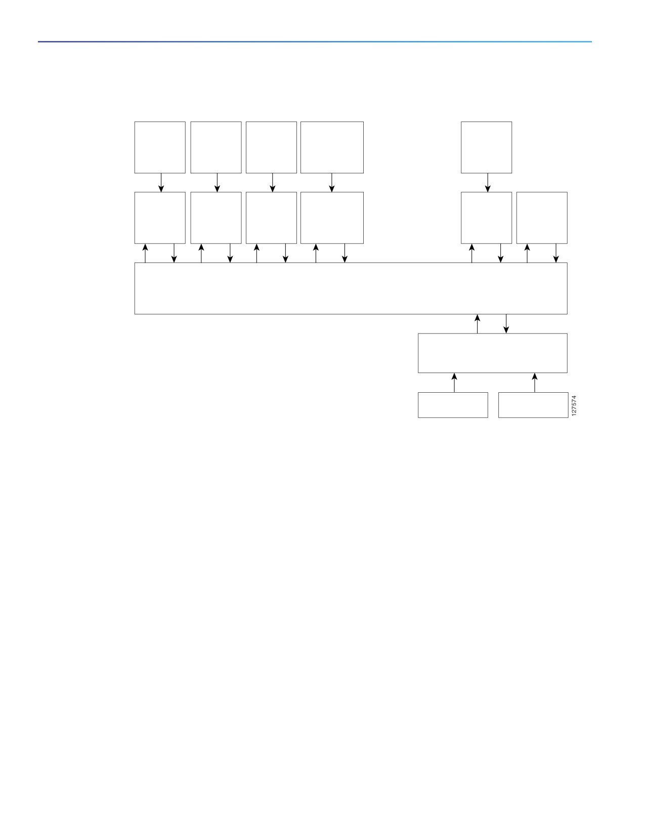
Figure 98 on page 832 shows the relationship between the EEM server, the core event publishers (event detectors), and
the event subscribers (policies). The event publishers screen events and when there is a match on an event specification
that is provided by the event subscriber. Event detectors notify the EEM server when an event occurs. The EEM policies
then implement recovery based on the current state of the system and the actions specified in the policy for the given
event.
831
Configuring Embedded Event Manager
Information About Embedded Event Manager
Figure 98
Embedded Event Manager Core Event Detectors
Core event publishers
Cisco
Syslog
event
IOS
OIR
Hardware
message
manager run
parser
events
timers
queue
CLI command
text
CLI
SYSLOG
OIR
NONE
Timer
Counter
event
event
event
event
event
event
detector
detector
detector
detector
detector
detector
EMBEDDED EVENT MANAGER SERVER
EEM POLICY DIRECTOR
Event
Subscribes to receive events
subscribers
and implements policy actions
EEM APPLET
EEM SCRIPT
See EEM Configuration for Cisco Integrated Services Router Platforms Guide for examples of EEM deployment.
This section includes the following topics:
Event Detectors, page 832
Embedded Event Manager Actions, page 833
Embedded Event Manager Policies, page 834
Embedded Event Manager Environment Variables, page 834
EEM 3.2, page 834
Event Detectors
EEM software programs known as event detectors determine when an EEM event occurs. Event detectors are separate
systems that provide an interface between the agent being monitored, for example SNMP, and the EEM polices where
an action can be implemented.
EEM allows these event detectors:
Application-specific event detector—Allows any EEM policy to publish an event.
IOS CLI event detector—Generates policies based on the commands entered through the CLI.
Generic Online Diagnostics (GOLD) event detector—Publishes an event when a GOLD failure event is detected on a
specified card and subcard.
Counter event detector—Publishes an event when a named counter crosses a specified threshold.
832
Configuring Embedded Event Manager
Information About Embedded Event Manager
Interface counter event detector—Publishes an event when a generic Cisco IOS interface counter for a specified
interface crosses a defined threshold. A threshold can be specified as an absolute value or an incremental value. For
example, if the incremental value is set to 50, an event would be published when the interface counter increases by
50.
This detector also publishes an event about an interface based on the rate of change for the entry and exit values.
None event detector—Publishes an event when the event manager run CLI command executes an EEM policy. EEM
schedules and runs policies on the basis on an event specification within the policy itself. An EEM policy must be
manually identified and registered before the event manager run command executes.
Online insertion and removal event detector—Publishes an event when a hardware insertion or removal (OIR) event
occurs.
Remote procedure call (RPC) event detector—Invokes EEM policies from outside the switch over an encrypted
connecting using Secure Shell (SSH) and uses Simple Object Access Protocol (SOAP) data encoding for exchanging
XML-based messages. It also runs EEM policies and then gets the output in a SOAP XML-formatted reply.
SNMP event detector—Allows a standard SNMP MIB object to be monitored and an event to be generated when
— The object matches specified values or crosses specified thresholds.
— The SNMP delta value, the difference between the monitored Object Identifier (OID) value at the beginning the
period and the actual OID value when the event is published, matches a specified value.
SNMP notification event detector—Intercepts SNMP trap and inform messages received by the switch. The event is
generated when an incoming message matches a specified value or crosses a defined threshold.
Syslog event detector—Allows for screening syslog messages for a regular expression pattern match. The selected
messages can be further qualified, requiring that a specific number of occurrences be logged within a specified time.
A match on a specified event criteria triggers a configured policy action.
Timer event detector—Publishes events for the following different types of timers:
— An absolute-time-of-day timer publishes an event when a specified absolute date and time occurs.
— A countdown timer publishes an event when a timer counts down to zero.
— A watchdog timer publishes an event when a timer counts down to zero. The timer automatically resets itself to
its initial value and starts to count down again.
— A CRON timer publishes an event by using a UNIX standard CRON specification to define when the event is to
be published. A CRON timer never publishes events more than once per minute.
Watchdog event detector (IOSWDSysMon)— Publishes an event when one of these events occurs:
— CPU utilization for a Cisco IOS process crosses a threshold.
— Memory utilization for a Cisco IOS process crosses a threshold.
Two events can be monitored at the same time, and the event publishing criteria requires that one or both events
cross their specified thresholds.
Embedded Event Manager Actions
These actions occur in response to an event:
Modifying a named counter.
Publishing an application-specific event.
833
Configuring Embedded Event Manager
Information About Embedded Event Manager
Generating an SNMP trap.
Generating prioritized syslog messages.
Reloading the Cisco IOS software.
Embedded Event Manager Policies
EEM can monitor events and provide information, or take corrective action when the monitored events occur or a
threshold is reached. An EEM policy is an entity that defines an event and the actions to be taken when that event occurs.
There are two types of EEM policies: an applet or a script. An applet is a simple policy that is defined within the CLI
configuration. It is a concise method for defining event screening criteria and the actions to be taken when that event
occurs. Scripts are defined on the networking device by using an ASCII editor. The script, which can be a bytecode (.tbc)
and text (.tcl) script, is then copied to the networking device and registered with EEM. You can also register multiple
events in a .tcl file.
Cisco enhancements to TCL in the form of keyword extensions facilitate the development of EEM policies. These
keywords identify the detected event, the subsequent action, utility information, counter values, and system information.
For complete information on configuring EEM policies and scripts, see Embedded Event Manager Configuration Guide,
Cisco IOS Release 15M&T.
Embedded Event Manager Environment Variables
EEM uses environment variables in EEM policies. These variables are defined in an EEM policy tool command language
(TCL) script by running a CLI command and the event manager environment command.
User-defined variables
Defined by the user for a user-defined policy.
Cisco-defined variables
Defined by Cisco for a specific sample policy.
Cisco built-in variables (available in EEM applets)
Defined by Cisco and can be read-only or read-write. The read-only variables are set by the system before an applet
starts to execute. The single read-write variable, _exit_status, allows you to set the exit status for policies triggered
from synchronous events.
Cisco-defined environment variables and Cisco system-defined environment variables might apply to one specific event
detector or to all event detectors. Environment variables that are user-defined or defined by Cisco in a sample policy are
set by using the event manager environment global configuration command. You must defined the variables in the EEM
policy before you register the policy.
For information about the environmental variables that EEM supports, see Embedded Event Manager Configuration
Guide, Cisco IOS Release 15M&T.
EEM 3.2
EEM 3.2 introduces these event detectors:
Neighbor Discovery—Provides the ability to publish a policy to respond to automatic neighbor detection when:
— a Cisco Discovery Protocol (CDP) cache entry is added, deleted, or updated.
— a Link Layer Discovery Protocol (LLDP) cache entry is added, deleted or updated.
834
Configuring Embedded Event Manager
Prerequisites
— an interface link status changes.
— an interface line status changes.
Identity—Generates an event when AAA authorization and authentication is successful, when failure occurs, or after
normal user traffic on the port is allowed to flow.
Mac-Address-Table—Generates an event when a MAC address is learned in the MAC address table.
Note: The Mac-Address-Table event detector is supported only on switch platforms and can be used only on Layer
2 interfaces where MAC addresses are learned. Layer 3 interfaces do not learn addresses, and routers do not usually
support the MAC address-table infrastructure needed to notify EEM of a learned MAC address.
EEM 3.2 also introduces CLI commands to support the applets to work with the new event detectors.
Prerequisites
Review the Information About Embedded Event Manager, page 831.
If the action snmp-trap command is used, the snmp-server enable traps event-manager command must be
enabled to permit SNMP traps to be sent from the Cisco IOS device to the SNMP server. Other relevant snmp-server
commands must also be configured; for details see the action snmp-trap command page.
Guidelines and Limitations
The EEM feature is supported with both Lanbase and IP Services license starting with the 15.2(4)EC release for the IE
4010 and with the15.2(5)E release for IE 4000 and IE 5000. Prior to the 15.2(5)E release, IP Services license was required
on the IE 4000 and IE 5000 platforms.
For complete information about configuring embedded event manager, see Embedded Event Manager Configuration
Guide, Cisco IOS Release 15M&T.
Default Settings
No EEM policies are registered.
Configuring Embedded Event Manager
Registering and Defining an Embedded Event Manager Applet, page 835
Registering and Defining an Embedded Event Manager TCL Script, page 836
Registering and Defining an Embedded Event Manager Applet
BEFORE YOU BEGIN
Review the Information About Embedded Event Manager, page 831.
DETAILED STEPS
Note: Only one event applet command is allowed in an EEM applet. Multiple action applet commands are permitted. If
you do not specify the no event and no action commands, the applet is removed when you exit configuration mode.
835

Configuring Embedded Event Manager
Configuring Embedded Event Manager
Command
Purpose
1.
configure terminal
Enter global configuration mode.
2.
event manager applet
Register the applet with EEM and enter applet configuration
applet-name
mode.
3.
event snmp oid oid-value
Specify the event criteria that causes the EEM applet to run.
get-type {exact | next} entry-op
{gt | ge | eq | ne | lt | le} entry-val
(Optional) Exit criteria. If exit criteria are not specified, event
entry-val [exit-comb {or |and}]
monitoring is re-enabled immediately.
[exit-op {gt | ge | eq | ne | lt | le}]
[exit-val exit-val] [exit-time
exit-time-val] poll-interval
poll-int-val
4.
action label syslog [priority
Specify the action when an EEM applet is triggered. Repeat this
priority-level] msg msg-text
action to add other CLI commands to the applet.
(Optional) The priority keyword specifies the priority level of
the syslog messages. If selected, you need to define the
priority-level argument.
For msg-text, the argument can be character text, an
environment variable, or a combination of the two.
5.
end
Exit applet configuration mode and return to privileged EXEC
mode.
EXAMPLE
The following example shows how to configure an EEM applet that runs when there is an exact match on the value of a
specified SNMP object ID that represents the amount of current process memory.
Switch(config-applet)# event snmp oid 1.3.6.1.4.1.9.9.48.1.1.1.6.1 get-type exact entry-op lt entry-val
5120000 poll-interval 10
These examples show actions that are taken in response to an EEM event:
Switch(config-applet)# action 1.0 syslog priority critical msg "Memory exhausted; current available
memory is $_snmp_oid_val bytes"
Switch (config-applet)# action 2.0 force-switchover
Registering and Defining an Embedded Event Manager TCL Script
BEFORE YOU BEGIN
Review the Information About Embedded Event Manager, page 831.
836

Configuring Embedded Event Manager
Verifying Configuration
DETAILED STEPS
Command
Purpose
1.
configure terminal
Enter global configuration mode.
1.
show event manager
(Optional) The show event manager environment command
environment [all | variable-name]
displays the name and value of the EEM environment variables.
(Optional) The all keyword displays the EEM environment
variables.
(Optional) The variable-name argument displays information
about the specified environment variable.
2.
configure terminal
Enter global configuration mode.
3.
event manager environment
Configure the value of the specified EEM environment variable.
variable-name string
Repeat this step for all the required environment variables.
4.
event manager policy
Register the EEM policy to run when the specified event defined
policy-file-name [type system]
within the policy occurs.
[trap]
5.
exit
Exit global configuration mode and return to privileged EXEC
mode.
EXAMPLE
This example shows the sample output for the show event manager environment command:
Switch# show event manager environment all
No. Name
Value
1
_cron_entry
0-59/2 0-23/1 * * 0-6
2
_show_cmd
show ver
3
_syslog_pattern
.*UPDOWN.*Ethernet1/0.*
4
_config_cmd1
interface Ethernet1/0
5
_config_cmd2
no shut
This example shows a CRON timer environment variable, which is assigned by the software, to be set to every second
minute, every hour of every day:
Switch (config)# event manager environment_cron_entry 0-59/2 0-23/1 * * 0-6
This example shows the sample EEM policy named tm_cli_cmd.tcl registered as a system policy. The system policies
are part of the Cisco IOS image. User-defined TCL scripts must first be copied to flash memory.
Switch (config)# event manager policy tm_cli_cmd.tcl type system
Verifying Configuration
To display information about EEM, including EEM registered policies and EEM history data, see Cisco IOS Embedded
Event Manager Command Reference.
Configuration Example
This example shows the output for EEM when one of the fields specified by an SNMP object ID crosses a defined
threshold:
837
Configuring Embedded Event Manager
Related Documents
Switch(config-applet)# event snmp oid 1.3.6.1.4.1.9.9.48.1.1.1.6.1 get-type exact entry-op lt entry-val
5120000 poll-interval 10
These examples show actions that are taken in response to an EEM event:
Switch(config-applet)# action 1.0 syslog priority critical msg "Memory exhausted; current available
memory is $_snmp_oid_val bytes"
Switch (config-applet)# action 2.0 force-switchover
This example shows the sample output for the show event manager environment command:
Switch# show event manager environment all
No. Name
Value
1
_cron_entry
0-59/2 0-23/1 * * 0-6
2
_show_cmd
show ver
3
_syslog_pattern
.*UPDOWN.*Ethernet1/0.*
4
_config_cmd1
interface Ethernet1/0
5
_config_cmd2
no shut
This example shows a CRON timer environment variable, which is assigned by the software, to be set to every second
minute, every hour of every day:
Switch (config)# event manager environment_cron_entry 0-59/2 0-23/1 * * 0-6
This example shows the sample EEM policy named tm_cli_cmd.tcl registered as a system policy. The system policies
are part of the Cisco IOS image. User-defined TCL scripts must first be copied to flash memory.
Switch (config)# event manager policy tm_cli_cmd.tcl type system
Related Documents
Cisco IOS Master Command List, All Releases
Cisco IOS Embedded Event Manager Command Reference
Cisco IOS 15.2M&T Command References, Network Management
Embedded Event Manager Configuration Guide, Cisco IOS Release 15M&T
838
Configuring IP Unicast Routing
This chapter describes how to configure IP Version 4 (IPv4) unicast routing on the Cisco Industrial Ethernet Switches,
hereafter referred to as switch.
Note: Dynamic routing protocols are only supported on switches running IP Services feature set. Static routing is
supported on Lan Base feature set.
For more detailed IPv4 unicast configuration information and complete syntax and usage information for the commands
used in this chapter, see documents listed in the Related Documents, page
966.
This chapter includes the following sections:
Information About IP Routing, page 839
Prerequisites, page 840
Guidelines and Limitations, page 840
Configuring IP Addressing, page 841
Enabling IPv4 Unicast Routing, page 858
Configuring RIP, page 859
Configuring OSPF, page 865
Configuring EIGRP, page 880
Configuring BGP, page 888
Configuring ISO CLNS Routing, page 913
Configuring BFD, page 925
Configuring Multi-VRF CE, page 936
Configuring Protocol-Independent Features, page 948
Verifying Configuration, page 966
Related Documents, page 966
Information About IP Routing
In an IP network, each subnetwork is mapped to an individual VLAN. However, network devices in different VLANs cannot
communicate with one another without a Layer 3 device (router) to route traffic between the VLAN, referred to as
inter-VLAN routing. You configure one or more routers to route traffic to the appropriate destination VLAN.
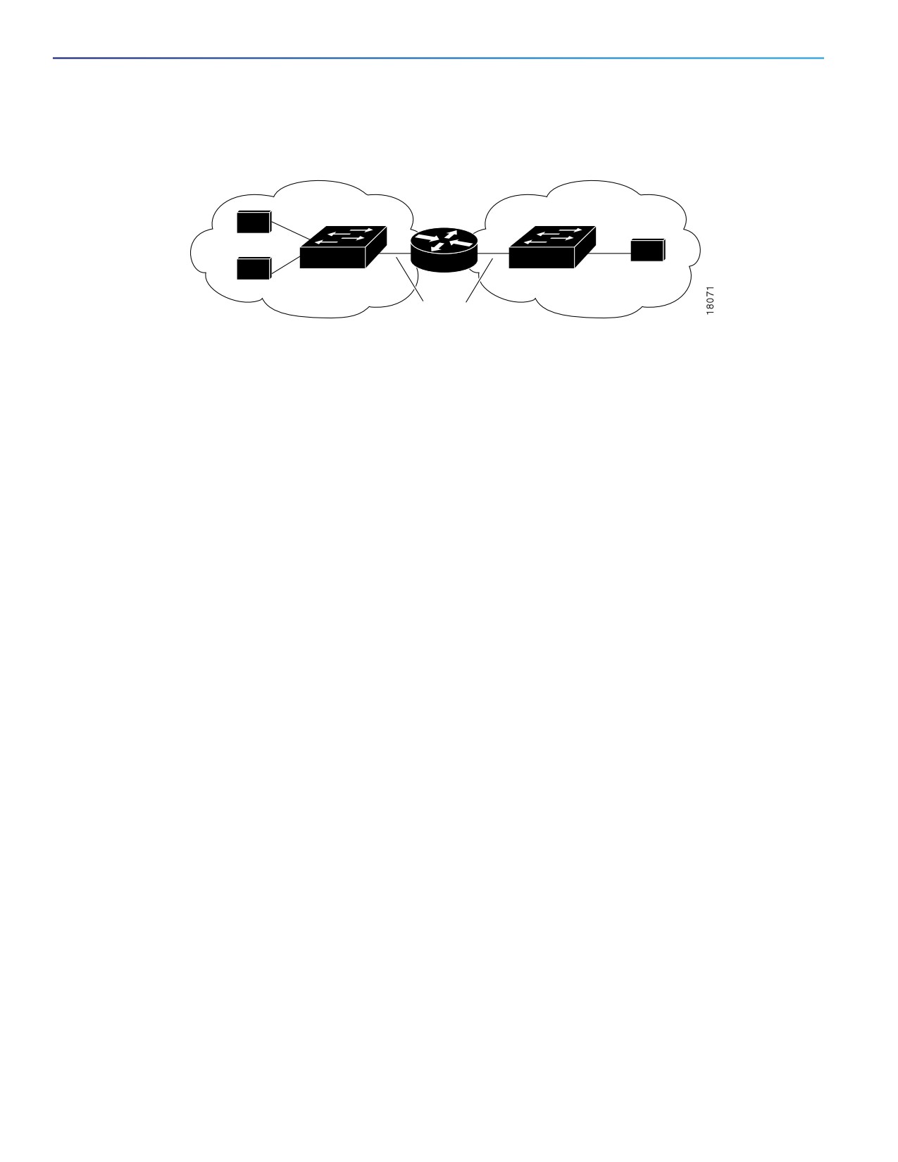
Figure 99 on page 840 shows a basic routing topology. Switch A is in VLAN 10, and Switch B is in VLAN 20. The router
has an interface in each VLAN.
839
Configuring IP Unicast Routing
Prerequisites
Figure 99
Routing Topology Example
VLAN 10
VLAN 20
Switch A
Switch B
A
Host
C
B
Host
Host
ISL Trunks
When Host A in VLAN 10 needs to communicate with Host B in VLAN 10, it sends a packet addressed to that host.
Switch A forwards the packet directly to Host B, without sending it to the router.
When Host A sends a packet to Host C in VLAN 20, Switch A forwards the packet to the router, which receives the traffic
on the VLAN 10 interface. The router checks the routing table, finds the correct outgoing interface, and forwards the
packet on the VLAN 20 interface to Switch B. Switch B receives the packet and forwards it to Host C.
Types of Routing
Routers and Layer 3 switches can route packets in the following ways:
By using default routing—sending traffic with a destination unknown to the router to a default outlet or destination.
By using preprogrammed static routes for the traffic
Static unicast routing forwards packets from predetermined ports through a single path into and out of a network.
Static routing does not automatically respond to changes in the network and therefore, might result in unreachable
destinations.
By dynamically calculating routes by using a routing protocol
Dynamic routing protocols are used by routers to dynamically calculate the best route for forwarding traffic. Routing
protocols supported by the switch are Routing Information Protocol (RIP), Border Gateway Protocol (BGP), Open
Shortest Path First (OSPF) protocol, Enhanced IGRP (EIGRP), System-to-Intermediate System (IS-IS), and
Bidirectional Forwarding Detection (BFD).
Prerequisites
In order to use dynamic routing protocols, an IP Services License is needed.
To support VLAN interfaces, create and configure VLANs on the switch, and assign VLAN membership to Layer 2
interfaces.
By default, IPv4 routing is disabled on the switch, and you must enable it before routing can take place. See Enabling
IPv4 Unicast Routing, page 858.
We recommend that you configure the BFD interval parameters on an interface before configuring the routing
protocol commands, especially when using EIGRP. For information about BFD, see Configuring BFD, page 925.
Guidelines and Limitations
In the following procedures, the specified interface must be one of these Layer 3 interfaces:
— A routed port: a physical port configured as a Layer 3 port by using the no switchport interface configuration
command.
840
Configuring IP Unicast Routing
Configuring IP Addressing
— A switch virtual interface (SVI): a VLAN interface created by using the interface vlan vlan_id global configuration
command and by default a Layer 3 interface.
— An EtherChannel port channel in Layer 3 mode: a port-channel logical interface created by using the interface
port-channel port-channel-number global configuration command and binding the Ethernet interface into the
channel group.
The switch does not support tunnel interfaces for unicast routed traffic.
All Layer 3 interfaces on which routing will occur must have IP addresses assigned to them. See Assigning IP
Addresses to Network Interfaces, page 842.
A Layer 3 switch can have an IP address assigned to each routed port and SVI. The number of routed ports and SVIs
that you can configure is not limited by software. However, the interrelationship between this number and the number
and volume of features being implemented might have an impact on CPU utilization because of hardware limitations.
To support IPv4 routing, use the sdm prefer default global configuration command to set the Switch Database
Management (sdm) feature to balance resources. For more information on the SDM templates, see the sdm prefer
command in the command reference listed in the Related Documents, page 966.
Steps for Configuring Routing
Configuring IPv4 routing consists of several main procedures:
Configure Layer 3 interfaces.
Enable IPv4 routing on the switch.
Assign IPv4 addresses to the Layer 3 interfaces.
Enable selected routing protocols on the switch.
Configure routing protocol parameters (optional).
Configuring IP Addressing
IP routing requires that Layer 3 network interfaces are assigned IP addresses to enable the interfaces and to allow
communication with the hosts on interfaces that use IP. These sections describe how to configure various IP addressing
features. Assigning IP addresses to the interface is required; the other procedures are optional.
Default Addressing Configuration, page 842
Assigning IP Addresses to Network Interfaces, page 842
Configuring Address Resolution Methods, page 845
Routing Assistance When IP Routing is Disabled, page 849
Configuring Broadcast Packet Handling, page 852
Monitoring and Maintaining IP Addressing, page 857
841

Configuring IP Unicast Routing
Configuring IP Addressing
Default Addressing Configuration
Feature
Default Setting
IP address
None defined.
ARP
No permanent entries in the Address Resolution Protocol (ARP) cache.
Encapsulation: Standard Ethernet-style ARP.
Timeout: 14400 seconds (4 hours).
IP broadcast address
255.255.255.255 (all ones).
IP classless routing
Enabled.
IP default gateway
Disabled.
IP directed broadcast
Disabled (all IP directed broadcasts are dropped).
IP domain
Domain list: No domain names defined.
Domain lookup: Enabled.
Domain name: Enabled.
IP forward-protocol
If a helper address is defined or User Datagram Protocol (UDP) flooding is configured, UDP
forwarding is enabled on default ports.
Any-local-broadcast: Disabled.
Turbo-flood: Disabled.
IP helper address
Disabled.
IP host
Disabled.
IRDP
Disabled.
Defaults when enabled:
Broadcast IRDP advertisements.
Maximum interval between advertisements: 600 seconds.
Minimum interval between advertisements: 0.75 times max interval.
Preference: 0.
IP proxy ARP
Enabled.
IP routing
Disabled.
IP subnet-zero
Disabled.
Assigning IP Addresses to Network Interfaces
An IP address identifies a location to which IP packets can be sent. An interface can have one primary IP address. A mask
identifies the bits that denote the network number in an IP address. When you use the mask to subnet a network, the
mask is referred to as a subnet mask.
BEFORE YOU BEGIN
To receive an assigned network number, contact your Internet service provider.
842

Configuring IP Unicast Routing
Configuring IP Addressing
DETAILED STEPS
Command
Purpose
1.
configure terminal
Enter global configuration mode.
2.
interface interface-id
Enter interface configuration mode, and specify the
Layer 3 interface to configure.
3.
no shutdown
Enable the interface if necessary. User network
interfaces (UNIs) and enhanced network interfaces
(ENIs) are disabled by default; network node interfaces
(NNIs) are enabled by default.
4.
no switchport
Remove the interface from Layer 2 configuration mode
(if it is a physical interface).
5.
ip address ip-address subnet-mask
Configure the IP address and IP subnet mask.
6.
end
Return to privileged EXEC mode.
7.
show interfaces [interface-id]
Verify your entries.
show ip interface [interface-id]
show running-config interface
[interface-id]
8.
copy running-config startup-config
(Optional) Save your entries in the configuration file.
EXAMPLE
Switch# configure terminal
Enter configuration commands, one per line. End with CNTL/Z.
Switch(config)# interface gi0/2
Switch(config-if)# no switchport
Switch(config-if)# ip address 10.1.5.1 255.255.255.0
Switch(config-if)# end
Enabling Subnet Zero
Enabling subnet zero provides the ability to configure and route to subnet 0 subnets.
You can use the all ones subnet (131.108.255.0) and even though it is discouraged, you can enable the use of subnet
zero if you need the entire subnet space for your IP address.
BEFORE YOU BEGIN
Subnetting with a subnet address of zero is strongly discouraged because of the problems that can arise if a network
and a subnet have the same addresses. For example, if network 131.108.0.0 is subnetted as 255.255.255.0, subnet zero
would be written as 131.108.0.0, which is the same as the network address.
843

Configuring IP Unicast Routing
Configuring IP Addressing
DETAILED STEPS
Command
Purpose
1.
configure terminal
Enter global configuration mode.
2.
ip subnet-zero
Enable the use of subnet zero for interface addresses and
routing updates.
3.
end
Return to privileged EXEC mode.
4.
show running-config
Verify your entry.
5.
copy running-config
(Optional) Save your entry in the configuration file.
startup-config
Use the no ip subnet-zero global configuration command to restore the default and disable the use of subnet zero.
EXAMPLE
Switch# configure terminal
Enter configuration commands, one per line. End with CNTL/Z.
Switch(config)# ip subnet-zero
Switch(config)# end
Classless Routing
By default, classless routing behavior is enabled on the switch when it is configured to route. With classless routing, if a
router receives packets for a subnet of a network with no default route, the router forwards the packet to the best
supernet route. A supernet consists of contiguous blocks of Class C address spaces used to simulate a single, larger
address space and is designed to relieve the pressure on the rapidly depleting Class B address space.
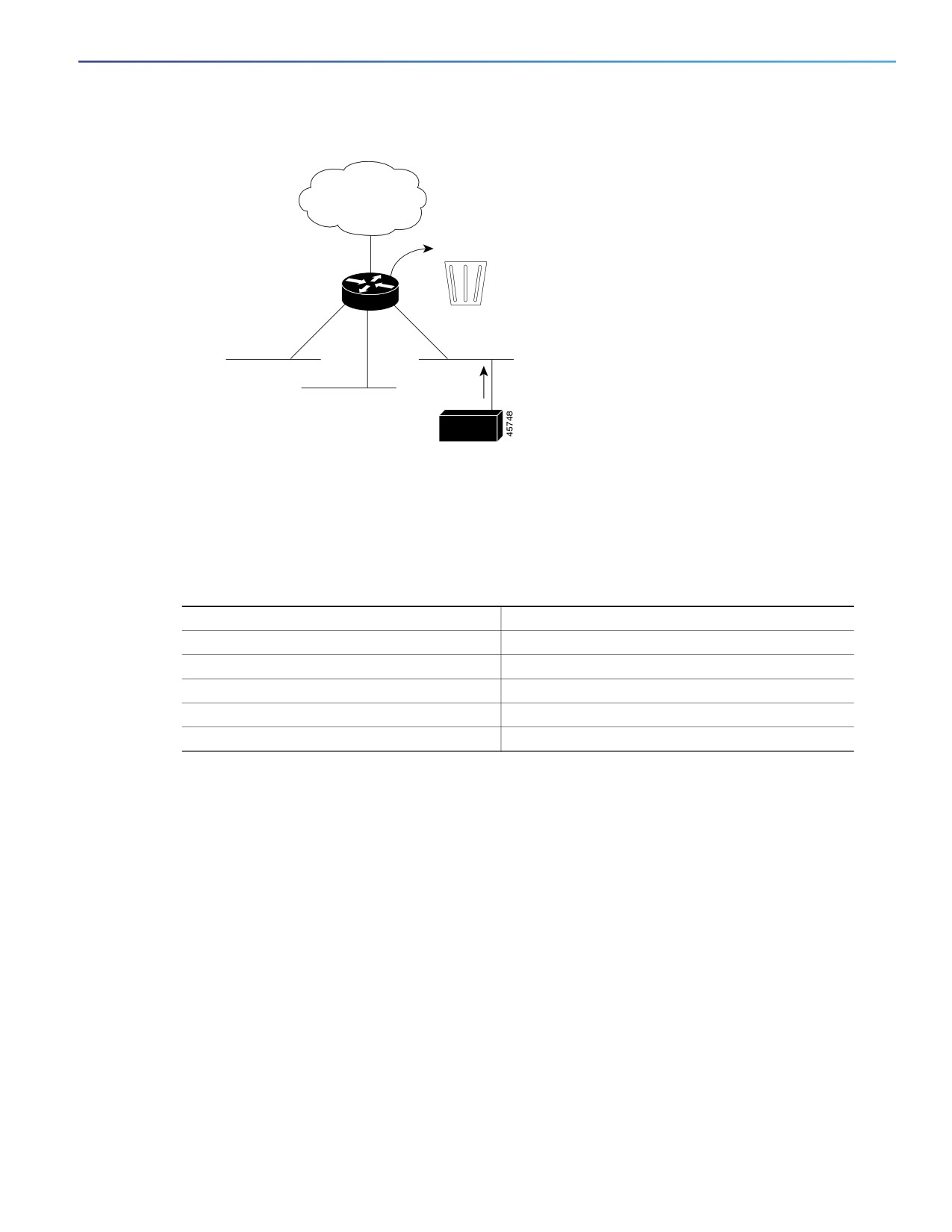
In Figure 100 on page 844, classless routing is enabled. When the host sends a packet to 120.20.4.1, instead of
discarding the packet, the router forwards it to the best supernet route. If you disable classless routing and a router
receives packets destined for a subnet of a network with no network default route, the router discards the packet.
Figure 100 IP Classless Routing
128.0.0.0/8
128.20.4.1
128.20.0.0
IP classless
128.20.1.0
128.20.3.0
128.20.2.0
128.20.4.1
Host
In Figure 101 on page 845, the router in network 128.20.0.0 is connected to subnets 128.20.1.0, 128.20.2.0, and
128.20.3.0. If the host sends a packet to 120.20.4.1, because there is no network default route, the router discards the
packet.
844
Configuring IP Unicast Routing
Configuring IP Addressing
Figure 101 No IP Classless Routing
128.0.0.0/8
128.20.4.1
128.20.0.0
Bit bucket
128.20.1.0
128.20.3.0
128.20.2.0
128.20.4.1
Host
To prevent the switch from forwarding packets destined for unrecognized subnets to the best supernet route possible,
you can disable classless routing behavior.
BEFORE YOU BEGIN
Review the Information About IP Routing, page 839.
DETAILED STEPS
Command
Purpose
1.
configure terminal
Enter global configuration mode.
2.
no ip classless
Disable classless routing behavior.
3.
end
Return to privileged EXEC mode.
4.
show running-config
Verify your entry.
5.
copy running-config startup-config
(Optional) Save your entry in the configuration file.
To restore the default and have the switch forward packets destined for a subnet of a network with no network default
route to the best supernet route possible, use the ip classless global configuration command.
EXAMPLE
Switch# configure terminal
Enter configuration commands, one per line. End with CNTL/Z.
Switch(config)# no ip classless
Switch(config)# end
Configuring Address Resolution Methods
You can control interface-specific handling of IP by using address resolution. A device using IP can have both a local
address or MAC address, which uniquely defines the device on its local segment or LAN, and a network address, which
identifies the network to which the device belongs. To communicate with a device on Ethernet, the software must learn
the MAC address of the device. The process of learning the MAC address from an IP address is called address resolution.
The process of learning the IP address from the MAC address is called reverse address resolution.
The switch can use these forms of address resolution:
845
Configuring IP Unicast Routing
Configuring IP Addressing
Address Resolution Protocol (ARP) is used to associate IP address with MAC addresses. Taking an IP address as
input, ARP learns the associated MAC address and then stores the IP address/MAC address association in an ARP
cache for rapid retrieval. Then the IP datagram is encapsulated in a link-layer frame and sent over the network.
Encapsulation of IP datagrams and ARP requests or replies on IEEE 802 networks other than Ethernet is specified by
the Subnetwork Access Protocol (SNAP).
Proxy ARP helps hosts with no routing tables learn the MAC addresses of hosts on other networks or subnets. If the
switch (router) receives an ARP request for a host that is not on the same interface as the ARP request sender, and
if the router has all of its routes to the host through other interfaces, it generates a proxy ARP packet giving its own
local data link address. The host that sent the ARP request then sends its packets to the router, which forwards them
to the intended host.
The switch also uses the Reverse Address Resolution Protocol (RARP), which functions the same as ARP does, except
that the RARP packets request an IP address instead of a local MAC address. Using RARP requires a RARP server on the
same network segment as the router interface. Use the ip rarp-server address interface configuration command to
identify the server.
For more information on RARP, see IP Addressing: ARP Configuration Guide, Cisco IOS Release 15M&T.
You can perform these tasks to configure address resolution:
Defining a Static ARP Cache, page 846
Setting ARP Encapsulation, page 847
Enabling Proxy ARP, page 848
Defining a Static ARP Cache
ARP and other address resolution protocols provide dynamic mapping between IP addresses and MAC addresses.
Because most hosts support dynamic address resolution, you usually do not need to specify static ARP cache entries. If
you must define a static ARP cache entry, you can do so globally, which installs a permanent entry in the ARP cache that
the switch uses to translate IP addresses into MAC addresses. Optionally, you can also specify that the switch respond
to ARP requests as if it were the owner of the specified IP address. If you do not want the ARP entry to be permanent,
you can specify a timeout period for the ARP entry.
BEFORE YOU BEGIN
Review the Configuring Address Resolution Methods, page 845.
846