Cisco Industrial Ethernet 4000, 4010 and 5000 Switch Software. Configuration Guide (2022) - page 29
Configuring MSDP
Configuring MSDP
Filter all incoming SA messages from an MSDP peer
Specify an IP extended access list to pass certain source/group pairs
Filter based on match criteria in a route map
Follow this procedure to apply a filter. This procedure is optional.
BEFORE YOU BEGIN
For best practice information related to configuring MSDP SA message filters, see the Multicast Source Discovery
Protocol SA Filter Recommendations tech note.
787

Configuring MSDP
Configuring MSDP
DETAILED STEPS
Table 0-7
Command
Purpose
1.
configure terminal
Enter global configuration mode.
2.
ip msdp sa-filter in ip-address |
Filter all SA messages from the specified MSDP peer.
name
or
or
From the specified peer, pass only those SA messages that
ip msdp sa-filter in {ip-address |
pass the IP extended access list. The range for the extended
name} list access-list-number
access-list-number is 100 to 199.
If both the list and the route-map keywords are used, all
conditions must be true to pass any (S,G) pair in incoming SA
messages.
or
or
ip msdp sa-filter in {ip-address |
From the specified MSDP peer, pass only those SA messages
name} route-map map-tag
that meet the match criteria in the route map map-tag.
If all match criteria are true, a permit from the route map
passes routes through the filter. A deny will filter routes.
3.
access-list access-list-number
(Optional) Create an IP extended access list, repeating the
{deny | permit} protocol source
command as many times as necessary.
source-wildcard destination
destination-wildcard
For access-list-number, enter the number specified in
Step 2.
The deny keyword denies access if the conditions are
matched. The permit keyword permits access if the
conditions are matched.
For protocol, enter ip as the protocol name.
For source, enter the number of the network or host from
which the packet is being sent.
For source-wildcard, enter the wildcard bits in dotted
decimal notation to be applied to the source. Place ones
in the bit positions that you want to ignore.
For destination, enter the number of the network or host to
which the packet is being sent.
For destination-wildcard, enter the wildcard bits in dotted
decimal notation to be applied to the destination. Place
ones in the bit positions that you want to ignore.
Recall that the access list is always terminated by an implicit
deny statement for everything.
4.
end
Return to privileged EXEC mode.
5.
show running-config
Verify your entries.
6.
copy running-config
(Optional) Save your entries in the configuration file.
startup-config
788

Configuring MSDP
Configuring MSDP
To remove the filter, use the no ip msdp sa-filter in {ip-address | name} [list access-list-number] [route-map map-tag]
global configuration command.
EXAMPLE
This example shows how to filter all SA messages from the peer named switch.cisco.com:
Switch(config)# ip msdp peer switch.cisco.com connect-source gigabitethernet0/1
Switch(config)# ip msdp sa-filter in switch.cisco.com
Configuring an MSDP Mesh Group
An MSDP mesh group is a group of MSDP speakers that have fully meshed MSDP connectivity among one another. Any
SA messages received from a peer in a mesh group are not forwarded to other peers in the same mesh group. Thus, you
reduce SA message flooding and simplify peer-RPF flooding. Use the ip msdp mesh-group global configuration
command when there are multiple RPs within a domain. It is especially used to send SA messages across a domain. You
can configure multiple mesh groups (with different names) in a single switch. This procedure is optional.
DETAILED STEPS
Table 0-8
Command
Purpose
1.
configure terminal
Enter global configuration mode.
2.
ip msdp mesh-group name
Configure an MSDP mesh group, and specify the MSDP peer
{ip-address | name}
belonging to that mesh group.
By default, the MSDP peers do not belong to a mesh group.
For name, enter the name of the mesh group.
For ip-address | name, enter the IP address or name of the
MSDP peer to be a member of the mesh group.
3.
end
Return to privileged EXEC mode.
4.
show running-config
Verify your entries.
5.
copy running-config
(Optional) Save your entries in the configuration file.
startup-config
6.
Repeat this procedure on each MSDP peer in the group.
To remove an MSDP peer from a mesh group, use the no ip msdp mesh-group name {ip-address | name} global
configuration command.
EXAMPLE
The following example shows how to configure the MSDP peer at address 192.168.1.3 to be a member of the mesh
group named internal:
Switch(config)# ip msdp mesh-group internal 192.168.1.3
789

Configuring MSDP
Configuring MSDP
Shutting Down an MSDP Peer
If you want to configure many MSDP commands for the same peer and you do not want the peer to become active, you
can shut down the peer, configure it, and later bring it up. When a peer is shut down, the TCP connection is terminated
and is not restarted. You can also shut down an MSDP session without losing configuration information for the peer. This
procedure is optional.
DETAILED STEPS
Table 0-9
Command
Purpose
1.
configure terminal
Enter global configuration mode.
2.
ip msdp shutdown {peer-name |
Administratively shut down the specified MSDP peer without
peer address}
losing configuration information.
For peer-name | peer address, enter the IP address or name of
the MSDP peer to shut down.
3.
end
Return to privileged EXEC mode.
4.
show running-config
Verify your entries.
5.
copy running-config
(Optional) Save your entries in the configuration file.
startup-config
To bring the peer back up, use the no ip msdp shutdown {peer-name | peer address} global configuration command.
The TCP connection is reestablished.
EXAMPLE
The following example shows how to shut down the MSDP peer at IP address 192.168.7.20:
Switch(config)# ip msdp shutdown 192.168.7.20
Including a Bordering PIM Dense-Mode Region in MSDP
You can configure MSDP on a switch that borders a PIM sparse-mode region with a dense-mode region. By default,
active sources in the dense-mode region do not participate in MSDP.
Follow this procedure to configure the border router to send SA messages for sources active in the dense-mode region
to the MSDP peers. This procedure is optional.
BEFORE YOU BEGIN
We do not recommend using the ip msdp border sa-address global configuration command. It is better to configure
the border router in the sparse-mode domain to proxy-register sources in the dense-mode domain to the RP of the
sparse-mode domain and have the sparse-mode domain use standard MSDP procedures to advertise these
sources.
If you use the ip msdp border sa-address command, you must constrain the sources advertised by using the ip
msdp redistribute command. Configure the ip msdp redistribute command to apply to only local sources. Be aware
that this configuration can result in (S, G) state remaining long after a source in the dense mode domain has stopped
sending.
Note that the ip msdp originator-id global configuration command also identifies an interface to be used as the RP
address. If both the ip msdp border sa-address and the ip msdp originator-id global configuration commands are
configured, the address derived from the ip msdp originator-id command specifies the RP address.
790

Configuring MSDP
Configuring MSDP
DETAILED STEPS
Table 0-10
Command
Purpose
1.
configure terminal
Enter global configuration mode.
2.
ip msdp border sa-address
Configure the switch on the border between a dense-mode
interface-id
and sparse-mode region to send SA messages about active
sources in the dense-mode region.
For interface-id, specify the interface from which the IP
address is derived and used as the RP address in SA
messages.
The IP address of the interface is used as the Originator-ID,
which is the RP field in the SA message.
3.
ip msdp redistribute [list
Configure which (S,G) entries from the multicast routing table
access-list-name] [asn
are advertised in SA messages.
aspath-access-list-number]
For more information, see Redistributing Sources, page 780.
[route-map map]
4.
end
Return to privileged EXEC mode.
5.
show running-config
Verify your entries.
6.
copy running-config
(Optional) Save your entries in the configuration file.
startup-config
To return to the default setting (active sources in the dense-mode region do not participate in MSDP), use the no ip msdp
border sa-address interface-id global configuration command.
EXAMPLE
In the following example, the local router is not an RP. It borders a PIM sparse mode region with a dense mode region.
It uses the IP address of Ethernet interface 0 as the “RP” address in SA messages.
Switch(config)# ip msdp border sa-address ethernet0
Configuring an Originating Address other than the RP Address
You can allow an MSDP speaker that originates an SA message to use the IP address of the interface as the RP address
in the SA message by changing the Originator ID. You might change the Originator ID in one of these cases:
If you configure a logical RP on multiple switches in an MSDP mesh group.
If you have a switch that borders a PIM sparse-mode domain and a dense-mode domain. If a switch borders a
dense-mode domain for a site, and sparse-mode is being used externally, you might want dense-mode sources to
be known to the outside world. Because this switch is not an RP, it would not have an RP address to use in an SA
message. Therefore, this command provides the RP address by specifying the address of the interface.
This procedure is optional.
BEFORE YOU BEGIN
If both the ip msdp border sa-address and the ip msdp originator-id global configuration commands are configured,
the address derived from the ip msdp originator-id command specifies the address of the RP.
791

Configuring MSDP
Configuring MSDP
DETAILED STEPS
Table 0-11
Command
Purpose
1.
configure terminal
Enter global configuration mode.
2.
ip msdp originator-id interface-id
Configures the RP address in SA messages to be the address
of the originating device interface.
For interface-id, specify the interface on the local switch.
3.
end
Return to privileged EXEC mode.
4.
show running-config
Verify your entries.
5.
copy running-config
(Optional) Save your entries in the configuration file.
startup-config
To prevent the RP address from being derived in this way, use the no ip msdp originator-id interface-id global
configuration command.
EXAMPLE
The following example shows how to configure the IP address of Ethernet interface 1 as the RP address in SA messages:
Switch(config)# ip msdp originator-id ethernet1
792

Configuring MSDP
Verifying Configuration
Verifying Configuration
Table 47-59
Command
Purpose
debug ip msdp [peer-address | name] [detail]
Debugs an MSDP activity.
[routes]
debug ip msdp resets
Debugs MSDP peer reset reasons.
show ip msdp count
Displays the number of sources and groups
[autonomous-system-number]
originated in SA messages from each autonomous
system. The ip msdp cache-sa-state command
must be configured for this command to produce any
output.
show ip msdp peer [peer-address | name]
Displays detailed information about an MSDP peer.
show ip msdp sa-cache [group-address |
Displays (S,G) state learned from MSDP peers.
source-address | group-name | source-name]
[autonomous-system-number]
show ip msdp summary
Displays MSDP peer status and SA message counts.
To clear MSDP connections, statistics, or SA cache entries, use the following privileged EXEC commands:
Table 47-60
Command
Purpose
clear ip msdp peer peer-address |
Clears the TCP connection to the specified MSDP peer,
name
resetting all MSDP message counters.
clear ip msdp statistics [peer-address
Clears statistics counters for one or all the MSDP peers
| name]
without resetting the sessions.
clear ip msdp sa-cache
Clears the SA cache entries for all entries, all sources for a
[group-address | name]
specific group, or all entries for a specific source/group pair.
Configuration Example
This example shows a partial configuration of Router A and Router C in Figure 95 on page 776. Each of these ISPs have
more than one customer (like the customer in Figure 95 on page 776) who use default peering (no BGP or MBGP). In that
case, they might have similar configurations. That is, they accept SAs only from a default peer if the SA is permitted by
the corresponding prefix list.
Router A
Router(config)# ip msdp default-peer 10.1.1.1
Router(config)# ip msdp default-peer 10.1.1.1 prefix-list site-a
Router(config)# ip prefix-list site-b permit 10.0.0.0/1
Router C
Router(config)# ip msdp default-peer 10.1.1.1 prefix-list site-a
Router(config)# ip prefix-list site-b permit 10.0.0.0/1
This example shows how to enable the cache state for all sources in 171.69.0.0/16 sending to groups 224.2.0.0/16:
Switch(config)# ip msdp cache-sa-state 100
Switch(config)# access-list 100 permit ip 171.69.0.0 0.0.255.255 224.2.0.0 0.0.255.255
793
Configuring MSDP
Related Documents
This example shows how to configure the switch to send SA request messages to the MSDP peer at 171.69.1.1:
Switch(config)# ip msdp sa-request 171.69.1.1
The following example shows how to configure which (S, G) entries from the mroute table are advertised in SA messages
originated from AS 64512:
Switch(config)# ip msdp redistribute route-map customer-sources
Switch(config)# route-map customer-sources permit
Switch(config)# match as-path 100
Switch(config)# ip as-path access-list 100 permit ^64512$
This example shows how to configure the switch to filter SA request messages from the MSDP peer at 171.69.2.2. SA
request messages from sources on network 192.4.22.0 pass access list 1 and are accepted; all others are ignored.
Switch(config)# ip msdp filter sa-request 171.69.2.2 list 1
Switch(config)# access-list 1 permit 192.4.22.0 0.0.0.255
This example shows how to allow only (S,G) pairs that pass access list 100 to be forwarded in an SA message to the
peer named switch.cisco.com:
Switch(config)# ip msdp peer switch.cisco.com connect-source gigabitethernet0/1
Switch(config)# ip msdp sa-filter out switch.cisco.com list 100
Switch(config)# access-list 100 permit ip 171.69.0.0 0.0.255.255 224.20 0 0.0.255.255
The following example shows how to configure a TTL threshold of 8 hops:
Switch(config)# ip msdp ttl-threshold 192.168.1.5 8
This example shows how to filter all SA messages from the peer named switch.cisco.com:
Switch(config)# ip msdp peer switch.cisco.com connect-source gigabitethernet0/1
Switch(config)# ip msdp sa-filter in switch.cisco.com
The following example shows how to configure the MSDP peer at address 192.168.1.3 to be a member of the mesh
group named internal:
Switch(config)# ip msdp mesh-group internal 192.168.1.3
The following example shows how to shut down the MSDP peer at IP address 192.168.7.20:
Switch(config)# ip msdp shutdown 192.168.7.20
In the following example, the local router is not an RP. It borders a PIM sparse mode region with a dense mode region.
It uses the IP address of Ethernet interface 0 as the “RP” address in SA messages.
Switch(config)# ip msdp border sa-address ethernet0
The following example shows how to configure the IP address of Ethernet interface 1 as the RP address in SA messages:
Switch(config)# ip msdp originator-id ethernet1
Related Documents
Cisco IOS IP Multicast Command Reference
IP Multicast Configuration Guide Library, Cisco IOS Release 15M&T
Cisco IOS Master Command List, All Releases
794
Configuring IPv6 MLD Snooping
This chapter describes how to configure Multicast Listener Discovery (MLD) snooping on the Cisco Industrial Ethernet
Switches, hereafter referred to as switch. When the switch is running the IP services image, you can use MLD snooping
to enable efficient distribution of IP version 6 (IPv6) multicast data to clients and routers in a switched network.
Note: To use IPv6, you must configure the dual IPv4 and IPv6 Switch Database Management (SDM) template on the
switch. You select the template by entering the sdm prefer dual-ipv4-and-ipv6 global configuration command.
Note: For complete syntax and usage information for the commands used in this chapter, see the documents listed in
the Related Documents, page 807.
This chapter includes the following sections:
Information About MLD Snooping, page 795
Prerequisites, page 798
Guidelines and Limitations, page 798
Default Settings, page 799
Configuring IPv6 MLD Snooping, page 799
Verifying Configuration, page 805
Related Documents, page 807
Information About MLD Snooping
In IP version 4 (IPv4), Layer 2 switches can use Internet Group Management Protocol (IGMP) snooping to limit the flooding
of multicast traffic by dynamically configuring Layer 2 interfaces so that multicast traffic is forwarded to only those
interfaces associated with IP multicast devices. In IPv6, MLD snooping performs a similar function. With MLD snooping,
IPv6 multicast data is selectively forwarded to a list of ports that want to receive the data, instead of being flooded to all
ports in a VLAN. This list is constructed by snooping IPv6 multicast control packets.
MLD is a protocol used by IPv6 multicast routers to discover the presence of multicast listeners (nodes wishing to receive
IPv6 multicast packets) on its directly attached links and to discover which multicast packets are of interest to neighboring
nodes. MLD is derived from IGMP; MLD version 1 (MLDv1) is equivalent to IGMPv2 and MLD version 2 (MLDv2) is
equivalent to IGMPv3. MLD is a subprotocol of Internet Control Message Protocol version 6 (ICMPv6), and MLD
messages are a subset of ICMPv6 messages, identified in IPv6 packets by a preceding Next Header value of 58.
The switch supports two versions of MLD snooping:
MLDv1 snooping detects MLDv1 control packets and sets up traffic bridging based on IPv6 destination multicast
addresses.
MLDv2 basic snooping (MBSS) uses MLDv2 control packets to set up traffic forwarding based on IPv6 destination
multicast addresses.
The switch can snoop on both MLDv1 and MLDv2 protocol packets and bridge IPv6 multicast data based on destination
IPv6 multicast addresses.
795
Configuring IPv6 MLD Snooping
Information About MLD Snooping
Note: The switch does not support MLDv2 enhanced snooping (MESS), which sets up IPv6 source and destination
multicast address-based forwarding.
MLD snooping can be enabled or disabled globally or per VLAN. When MLD snooping is enabled, a per-VLAN IPv6
multicast MAC address table is constructed in software and a per-VLAN IPv6 multicast address table is constructed in
software and hardware. The switch then performs IPv6 multicast-address based bridging in hardware.
These sections describe some parameters of IPv6 MLD snooping:
MLD Messages, page 796
MLD Queries, page 796
Multicast Client Aging Robustness, page 797
Multicast Router Discovery, page 797
MLD Reports, page 797
MLD Done Messages and Immediate-Leave, page 798
Topology Change Notification Processing, page 798
MLD Messages
MLDv1 supports three types of messages:
Listener Queries are the equivalent of IGMPv2 queries and are either General Queries or Multicast-Address-Specific
Queries (MASQs).
Multicast Listener Reports are the equivalent of IGMPv2 reports.
Multicast Listener Done messages are the equivalent of IGMPv2 leave messages.
MLDv2 supports MLDv2 queries and reports, as well as MLDv1 Report and Done messages.
Message timers and state transitions resulting from messages being sent or received are the same as those of IGMPv2
messages. MLD messages that do not have valid link-local IPv6 source addresses are ignored by MLD routers and
switches.
MLD Queries
The switch sends out MLD queries, constructs an IPv6 multicast address database, and generates MLD group-specific
and MLD group-and-source-specific queries in response to MLD Done messages. The switch also supports report
suppression, report proxying, Immediate-Leave functionality, and static IPv6 multicast MAC-address configuration.
When MLD snooping is disabled, all MLD queries are flooded in the ingress VLAN.
When MLD snooping is enabled, received MLD queries are flooded in the ingress VLAN, and a copy of the query is sent
to the CPU for processing. From the received query, MLD snooping builds the IPv6 multicast address database. It detects
multicast router ports, maintains timers, sets report response time, learns the querier IP source address for the VLAN,
learns the querier port in the VLAN, and maintains multicast-address aging.
Note: When the IPv6 multicast router is a Catalyst 6500 switch and you are using extended VLANs (in the range 1006 to
4094), IPv6 MLD snooping must be enabled on the extended VLAN on the Catalyst 6500 switch in order for this switch
to receive queries on the VLAN. For normal-range VLANs (1 to 1005), it is not necessary to enable IPv6 MLD snooping
on the VLAN on the Catalyst 6500 switch.
When a group exists in the MLD snooping database, the switch responds to a group-specific query by sending an MLDv1
report. When the group is unknown, the group-specific query is flooded to the ingress VLAN.
796
Configuring IPv6 MLD Snooping
Information About MLD Snooping
When a host wants to leave a multicast group, it can send out an MLD Done message (equivalent to IGMP Leave
message). When the switch receives an MLDv1 Done message, if Immediate- Leave is not enabled, the switch sends an
MASQ to the port from which the message was received to determine if other devices connected to the port should
remain in the multicast group.
Multicast Client Aging Robustness
You can configure port membership removal from addresses based on the number of queries. A port is removed from
membership to an address only when there are no reports to the address on the port for the configured number of
queries. The default number is 2.
Multicast Router Discovery
Like IGMP snooping, MLD snooping performs multicast router discovery, with these characteristics:
Ports configured by a user never age out.
Dynamic port learning results from MLDv1 snooping queries and IPv6 PIMv2 packets.
If there are multiple routers on the same Layer 2 interface, MLD snooping tracks a single multicast router on the port
(the router that most recently sent a router control packet).
Dynamic multicast router port aging is based on a default timer of 5 minutes; the multicast router is deleted from the
router port list if no control packet is received on the port for 5 minutes.
IPv6 multicast router discovery only takes place when MLD snooping is enabled on the switch.
Received IPv6 multicast router control packets are always flooded to the ingress VLAN, whether or not MLD
snooping is enabled on the switch.
After the discovery of the first IPv6 multicast router port, unknown IPv6 multicast data is forwarded only to the
discovered router ports (before that time, all IPv6 multicast data is flooded to the ingress VLAN).
MLD Reports
The processing of MLDv1 join messages is essentially the same as with IGMPv2. When no IPv6 multicast routers are
detected in a VLAN, reports are not processed or forwarded from the switch. When IPv6 multicast routers are detected
and an MLDv1 report is received, an IPv6 multicast group address and an IPv6 multicast MAC address are entered in the
VLAN MLD database. Then all IPv6 multicast traffic to the group within the VLAN is forwarded using this address. When
MLD snooping is disabled, reports are flooded in the ingress VLAN.
When MLD snooping is enabled, MLD report suppression, called listener message suppression, is automatically enabled.
With report suppression, the switch forwards the first MLDv1 report received by a group to IPv6 multicast routers;
subsequent reports for the group are not sent to the routers. When MLD snooping is disabled, report suppression is
disabled, and all MLDv1 reports are flooded to the ingress VLAN.
The switch also supports MLDv1 proxy reporting. When an MLDv1 MASQ is received, the switch responds with MLDv1
reports for the address on which the query arrived if the group exists in the switch on another port and if the port on
which the query arrived is not the last member port for the address.
797
Configuring IPv6 MLD Snooping
Prerequisites
MLD Done Messages and Immediate-Leave
When the Immediate-Leave feature is enabled and a host sends an MLDv1 Done message (equivalent to an IGMP leave
message), the port on which the Done message was received is immediately deleted from the group.You enable
Immediate-Leave on VLANs and (as with IGMP snooping), you should only use the feature on VLANs where a single host
is connected to the port. If the port was the last member of a group, the group is also deleted, and the leave information
is forwarded to the detected IPv6 multicast routers.
When Immediate Leave is not enabled in a VLAN (which would be the case when there are multiple clients for a group
on the same port) and a Done message is received on a port, an MASQ is generated on that port. The user can control
when a port membership is removed for an existing address in terms of the number of MASQs. A port is removed from
membership to an address when there are no MLDv1 reports to the address on the port for the configured number of
queries.
The number of MASQs generated is configured by using the ipv6 mld snooping last-listener-query count global
configuration command. The default number is 2.
The MASQ is sent to the IPv6 multicast address for which the Done message was sent. If there are no reports sent to
the IPv6 multicast address specified in the MASQ during the switch maximum response time, the port on which the
MASQ was sent is deleted from the IPv6 multicast address database. The maximum response time is the time configured
by using the ipv6 mld snooping last-listener-query-interval global configuration command. If the deleted port is the
last member of the multicast address, the multicast address is also deleted, and the switch sends the address leave
information to all detected multicast routers.
Topology Change Notification Processing
When topology change notification (TCN) solicitation is enabled by using the ipv6 mld snooping tcn query solicit global
configuration command, MLDv1 snooping sets the VLAN to flood all IPv6 multicast traffic with a configured number of
MLDv1 queries before it begins sending multicast data only to selected ports. You set this value by using the ipv6 mld
snooping tcn flood query count global configuration command. The default is to send two queries. The switch also
generates MLDv1 global Done messages with valid link-local IPv6 source addresses when the switch becomes the STP
root in the VLAN or when it is configured by the user. This is same as done in IGMP snooping.
Prerequisites
Review the Information About MLD Snooping, page 795.
Guidelines and Limitations
You can configure MLD snooping characteristics at any time, but you must globally enable MLD snooping by using
the ipv6 mld snooping global configuration command for the configuration to take effect.
When the IPv6 multicast router is a Catalyst 6500 switch and you are using extended VLANs (in the range 1006 to
4094), IPv6 MLD snooping must be enabled on the extended VLAN on the Catalyst 6500 switch in order for this
switch to receive queries on the VLAN. For normal-range VLANs (1 to 1005), it is not necessary to enable IPv6 MLD
snooping on the VLAN on the Catalyst 6500 switch.
MLD snooping and IGMP snooping act independently of each other. You can enable both features at the same time
on the switch.
The maximum number of multicast entries allowed on the switch is determined by the configured SDM template.
The maximum number of address entries allowed for the switch is 1000.
798

Configuring IPv6 MLD Snooping
Default Settings
Default Settings
Table 48-61
Feature
Default Setting
MLD snooping (Global)
Disabled.
MLD snooping (per VLAN)
Enabled. MLD snooping must be globally enabled for VLAN
MLD snooping to take place.
IPv6 Multicast addresses
None configured.
IPv6 Multicast router ports
None configured.
MLD snooping Immediate Leave
Disabled.
MLD snooping robustness variable
Global: 2; Per VLAN: 0.
Note: The VLAN value overrides the global setting. When the
VLAN value is 0, the VLAN uses the global count.
Last listener query count
Global: 2; Per VLAN: 0.
Note: The VLAN value overrides the global setting. When the
VLAN value is 0, the VLAN uses the global count.
Last listener query interval
Global: 1000 (1 second); VLAN: 0.
Note: The VLAN value overrides the global setting. When the
VLAN value is 0, the VLAN uses the global interval.
TCN query solicit
Disabled.
TCN query count
2.
MLD listener suppression
Enabled.
Configuring IPv6 MLD Snooping
These sections describe how to configure IPv6 MLD snooping:
Enabling or Disabling MLD Snooping, page 799
Configuring a Static Multicast Group, page 801
Configuring a Multicast Router Port, page 801
Enabling MLD Immediate Leave, page 802
Configuring MLD Snooping Queries, page 803
Disabling MLD Listener Message Suppression, page 805
Enabling or Disabling MLD Snooping
By default, IPv6 MLD snooping is globally disabled on the switch and enabled on all VLANs. When MLD snooping is
globally disabled, it is also disabled on all VLANs. When you globally enable MLD snooping, the VLAN configuration
overrides the global configuration. That is, MLD snooping is enabled only on VLAN interfaces in the default state
(enabled).
799

Configuring IPv6 MLD Snooping
Configuring IPv6 MLD Snooping
You can enable and disable MLD snooping on a per-VLAN basis or for a range of VLANs, but if you globally disable MLD
snooping, it is disabled in all VLANs. If global snooping is enabled, you can enable or disable VLAN snooping.
Enabling MLD Snooping
DETAILED STEPS
Table 48-12
Command
Purpose
1.
configure terminal
Enter global configuration mode.
2.
ipv6 mld snooping
Globally enable MLD snooping on the switch.
3.
end
Return to privileged EXEC mode.
4.
copy running-config
(Optional) Save your entries in the configuration file.
startup-config
5.
reload
Reload the operating system.
To globally disable MLD snooping on the switch, use the no ipv6 mld snooping global configuration command.
EXAMPLE
This example shows how to enable MLD snooping globally:
Switch(config)# ipv6 mld snooping
Enabling MLD Snooping on a VLAN
DETAILED STEPS
Note: When the IPv6 multicast router is a Catalyst 6500 switch and you are using extended VLANs (in the range 1006 to
4094), IPv6 MLD snooping must be enabled on the extended VLAN on the Catalyst 6500 switch in order for this switch
to receive queries on the VLAN. For normal-range VLANs (1 to 1005), it is not necessary to enable IPv6 MLD snooping
on the VLAN on the Catalyst 6500 switch.
Table 48-13
Command
Purpose
1.
configure terminal
Enter global configuration mode.
2.
ipv6 mld snooping
Globally enable MLD snooping on the switch.
3.
ipv6 mld snooping vlan vlan-id
Enable MLD snooping on the VLAN.The VLAN ID range is 1
to 1001 and 1006 to 4094.
Note: MLD snooping must be globally enabled for VLAN
snooping to be enabled.
4.
end
Return to privileged EXEC mode.
5.
copy running-config startup-config
(Optional) Save your entries in the configuration file.
To disable MLD snooping on a VLAN interface, use the no ipv6 mld snooping vlan vlan-id global configuration command
for the specified VLAN number.
EXAMPLE
This example shows how to enable MLD snooping on a VLAN:
800

Configuring IPv6 MLD Snooping
Configuring IPv6 MLD Snooping
Switch(config)# ipv6 mld snooping vlan 100
Configuring a Static Multicast Group
Hosts or Layer 2 ports normally join multicast groups dynamically, but you can also statically configure an IPv6 multicast
address and member ports for a VLAN. Follow this procedure to add a Layer 2 port as a member of a multicast group.
DETAILED STEPS
Table 48-14
Command
Purpose
1.
configure terminal
Enter global configuration mode
2.
ipv6 mld snooping vlan vlan-id static
Statically configure a multicast group with a Layer 2 port
ipv6_multicast_address interface
as a member of a multicast group:
interface-id
vlan-id is the multicast group VLAN ID. The VLAN ID
range is 1 to 1001 and 1006 to 4094.
ipv6_multicast_address is the 128-bit group IPv6
address. The address must be in the form specified
in RFC 2373.
interface-id is the member port. It can be a physical
interface or a port channel (1 to 10).
3.
end
Return to privileged EXEC mode.
4.
show ipv6 mld snooping
Verify the static member port and the IPv6 address.
multicast-address user
or
show ipv6 mld snooping
multicast-address vlan vlan-id user
5.
copy running-config startup-config
(Optional) Save your entries in the configuration file.
To remove a Layer 2 port from the multicast group, use the no ipv6 mld snooping vlan vlan-id static mac-address
interface interface-id global configuration command. If all member ports are removed from a group, the group is
deleted.
EXAMPLE
This example shows how to statically configure an IPv6 multicast group:
Switch# configure terminal
Switch(config)# ipv6 mld snooping vlan 2 static FF12::3 interface gigabitethernet0/1
Switch(config)# end
Configuring a Multicast Router Port
Although MLD snooping learns about router ports through MLD queries and PIMv6 queries, you can also use the
command-line interface (CLI) to add a multicast router port to a VLAN. To add a multicast router port (add a static
connection to a multicast router), use the ipv6 mld snooping vlan mrouter global configuration command on the switch.
BEFORE YOU BEGIN
Static connections to multicast routers are supported only on switch ports.
801

Configuring IPv6 MLD Snooping
Configuring IPv6 MLD Snooping
DETAILED STEPS
Table 48-15
Command
Purpose
1.
configure terminal
Enter global configuration mode.
2.
ipv6 mld snooping vlan vlan-id mrouter
Specify the multicast router VLAN ID, and specify the
interface interface-id
interface to the multicast router.
The VLAN ID range is 1 to 1001 and 1006 to 4094.
The interface can be a physical interface or a port
channel. The port-channel range is 1 to 10.
3.
end
Return to privileged EXEC mode.
4.
show ipv6 mld snooping mrouter [vlan
Verify that IPv6 MLD snooping is enabled on the VLAN
vlan-id]
interface.
5.
copy running-config startup-config
(Optional) Save your entries in the configuration file.
To remove a multicast router port from the VLAN, use the no ipv6 mld snooping vlan vlan-id mrouter interface
interface-id global configuration command.
EXAMPLE
This example shows how to add a multicast router port to VLAN 200:
Switch# configure terminal
Switch(config)# ipv6 mld snooping vlan 200 mrouter interface gigabitethernet0/2
Switch(config)# exit
Enabling MLD Immediate Leave
When you enable MLDv1 Immediate Leave, the switch immediately removes a port from a multicast group when it detects
an MLD Done message on that port.
BEFORE YOU BEGIN
You should only use the Immediate-Leave feature when there is a single receiver present on every port in the VLAN.
When there are multiple clients for a multicast group on the same port, you should not enable Immediate-Leave in a
VLAN.
DETAILED STEPS
Table 48-16
Command
Purpose
1.
configure terminal
Enter global configuration mode.
2.
ipv6 mld snooping vlan vlan-id
Enable MLD Immediate Leave on the VLAN interface.
immediate-leave
3.
end
Return to privileged EXEC mode.
4.
show ipv6 mld snooping vlan vlan-id
Verify that Immediate Leave is enabled on the VLAN interface.
5.
copy running-config startup-config
(Optional) Save your entries in the configuration file.
To disable MLD Immediate Leave on a VLAN, use the no ipv6 mld snooping vlan vlan-id immediate-leave global
configuration command.
802
Configuring IPv6 MLD Snooping
Configuring IPv6 MLD Snooping
EXAMPLE
This example shows how to enable MLD Immediate Leave on VLAN 130:
Switch# configure terminal
Switch(config)# ipv6 mld snooping vlan 130 immediate-leave
Switch(config)# exit
Configuring MLD Snooping Queries
When Immediate Leave is not enabled and a port receives an MLD Done message, the switch generates MASQs on the
port and sends them to the IPv6 multicast address for which the Done message was sent. You can optionally configure
the number of MASQs that are sent and the length of time the switch waits for a response before deleting the port from
the multicast group.
803

Configuring IPv6 MLD Snooping
Configuring IPv6 MLD Snooping
DETAILED STEPS
Table 48-17
Command
Purpose
1.
configure terminal
Enter global configuration mode.
2.
ipv6 mld snooping
(Optional) Set the number of queries that are sent before
robustness-variable value
switch will deletes a listener (port) that does not respond to a
general query. The range is 1 to 3; the default is 2.
3.
ipv6 mld snooping vlan vlan-id
(Optional) Set the robustness variable on a VLAN basis, which
robustness-variable value
determines the number of general queries that MLD snooping
sends before aging out a multicast address when there is no
MLD report response. The range is 1 to 3; the default is 0.
When set to 0, the number used is the global robustness
variable value.
4.
ipv6 mld snooping
(Optional) Set the number of MASQs that the switch sends
last-listener-query-count count
before aging out an MLD client. The range is 1 to 7; the default
is 2. The queries are sent 1 second apart.
5.
ipv6 mld snooping vlan vlan-id
(Optional) Set the last-listener query count on a VLAN basis.
last-listener-query-count count
This value overrides the value configured globally. The range
is 1 to 7; the default is 0. When set to 0, the global count value
is used. Queries are sent 1 second apart.
6.
ipv6 mld snooping
(Optional) Set the maximum response time that the switch
last-listener-query-interval interval
waits after sending out a MASQ before deleting a port from the
multicast group. The range is 100 to 32,768 thousands of a
second. The default is 1000 (1 second).
7.
ipv6 mld snooping vlan vlan-id
(Optional) Set the last-listener query interval on a VLAN basis.
last-listener-query-interval interval
This value overrides the value configured globally. The range
is 0 to 32,768 thousands of a second. The default is 0. When
set to 0, the global last-listener query interval is used.
8.
ipv6 mld snooping tcn query solicit
(Optional) Enable topology change notification (TCN)
solicitation, which means that VLANs flood all IPv6 multicast
traffic for the configured number of queries before sending
multicast data to only those ports requesting to receive it. The
default is for TCN to be disabled.
9.
ipv6 mld snooping tcn flood query
(Optional) When TCN is enabled, specify the number of TCN
count count
queries to be sent. The range is from 1 to 10; the default is 2.
10.
end
Return to privileged EXEC mode.
11.
show ipv6 mld snooping querier
(Optional) Verify that the MLD snooping querier information for
[vlan vlan-id]
the switch or for the VLAN.
12.
copy running-config startup-config
(Optional) Save your entries in the configuration file.
EXAMPLE
This example shows how to set the MLD snooping global robustness variable to 3:
Switch# configure terminal
Switch(config)# ipv6 mld snooping robustness-variable 3
Switch(config)# exit
This example shows how to set the MLD snooping last-listener query count for a VLAN to 3:
Switch# configure terminal
Switch(config)# ipv6 mld snooping vlan 200 last-listener-query-count 3
Switch(config)# exit
804

Configuring IPv6 MLD Snooping
Verifying Configuration
This example shows how to set the MLD snooping last-listener query interval (maximum response time) to 2000 (2
seconds):
Switch# configure terminal
Switch(config)# ipv6 mld snooping last-listener-query-interval 2000
Switch(config)# exit
Disabling MLD Listener Message Suppression
MLD snooping listener message suppression is enabled by default. When it is enabled, the switch forwards only one MLD
report per multicast router query. When message suppression is disabled, multiple MLD reports could be forwarded to
the multicast routers.
DETAILED STEPS
Table 48-18
Command
Purpose
1.
configure terminal
Enter global configuration mode.
2.
no ipv6 mld snooping
Disable MLD message suppression.
listener-message-suppression
3.
end
Return to privileged EXEC mode.
4.
show ipv6 mld snooping
Verify that IPv6 MLD snooping report suppression is
disabled.
5.
copy running-config startup-config
(Optional) Save your entries in the configuration file.
To re-enable MLD message suppression, use the ipv6 mld snooping listener-message-suppression global
configuration command.
EXAMPLE
This example shows how to disable MLD message suppression:
Switch# configure terminal
Switch(config)# no ipv6 mld snooping listener-message-suppression
Switch(config)# end
Verifying Configuration
You can display MLD snooping information for dynamically learned and statically configured router ports and VLAN
interfaces. You can also display MAC address multicast entries for a VLAN configured for MLD snooping.
805

Configuring IPv6 MLD Snooping
Configuration Example
Table 48-62
Command
Purpose
show ipv6 mld snooping [vlan vlan-id]
Display the MLD snooping configuration information for all
VLANs on the switch or for a specified VLAN.
(Optional) Enter vlan vlan-id to display information for a
single VLAN. The VLAN ID range is 1 to 1001 and 1006 to
4094.
show ipv6 mld snooping mrouter [vlan
Display information on dynamically learned and manually
vlan-id]
configured multicast router interfaces. When you enable
MLD snooping, the switch automatically learns the
interface to which a multicast router is connected. These
are dynamically learned interfaces.
(Optional) Enter vlan vlan-id to display information for a
single VLAN. The VLAN ID range is 1 to 1001 and 1006 to
4094.
show ipv6 mld snooping querier [vlan
Display information about the IPv6 address and incoming
vlan-id]
port for the most-recently received MLD query messages
in the VLAN.
(Optional) Enter vlan vlan-id to display information for a
single VLAN.The VLAN ID range is 1 to 1001 and 1006 to
4094.
show ipv6 mld snooping
Display all IPv6 multicast address information or specific
multicast-address [vlan vlan-id] [count
IPv6 multicast address information for the switch or a
| dynamic | user]
VLAN.
Enter count to show the group count on the switch or
in a VLAN.
Enter dynamic to display MLD snooping learned
group information for the switch or for a VLAN.
Enter user to display MLD snooping user-configured
group information for the switch or for a VLAN.
show ipv6 mld snooping
Display MLD snooping for the specified VLAN and IPv6
multicast-address vlan vlan-id
multicast address.
[ipv6-multicast-address]
Configuration Example
This example shows how to enable MLD snooping globally:
Switch(config)# ipv6 mld snooping
This example shows how to enable MLD snooping on a VLAN:
Switch(config)# ipv6 mld snooping vlan 100
This example shows how to statically configure an IPv6 multicast group:
Switch# configure terminal
Switch(config)# ipv6 mld snooping vlan 2 static FF12::3 interface gigabitethernet0/1
Switch(config)# end
806
Configuring IPv6 MLD Snooping
Related Documents
This example shows how to add a multicast router port to VLAN 200:
Switch# configure terminal
Switch(config)# ipv6 mld snooping vlan 200 mrouter interface gigabitethernet0/2
Switch(config)# exit
This example shows how to enable MLD Immediate Leave on VLAN 130:
Switch# configure terminal
Switch(config)# ipv6 mld snooping vlan 130 immediate-leave
Switch(config)# exit
This example shows how to set the MLD snooping global robustness variable to 3:
Switch# configure terminal
Switch(config)# ipv6 mld snooping robustness-variable 3
Switch(config)# exit
This example shows how to set the MLD snooping last-listener query count for a VLAN to 3:
Switch# configure terminal
Switch(config)# ipv6 mld snooping vlan 200 last-listener-query-count 3
Switch(config)# exit
This example shows how to set the MLD snooping last-listener query interval (maximum response time) to 2000 (2
seconds):
Switch# configure terminal
Switch(config)# ipv6 mld snooping last-listener-query-interval 2000
Switch(config)# exit
This example shows how to disable MLD message suppression:
Switch# configure terminal
Switch(config)# no ipv6 mld snooping listener-message-suppression
Switch(config)# end
Related Documents
Cisco IOS IPv6 Command Reference
Cisco IOS Master Command List, All Releases
807
Configuring IPv6 MLD Snooping
Related Documents
808
Chapter Configuring HSRP and VRRP
Understanding HSRP
Configuring HSRP and VRRP
This chapter describes how to use Hot Standby Router Protocol (HSRP) to provide routing redundancy
for routing IP traffic not dependent on the availability of any single router. HSRP for IPv4 is supported
on switches running the IP services image.
You can also use a version of HSRP in Layer 2 mode to configure a redundant command switch to take
over cluster management if the cluster command switch fails.
For complete syntax and usage information for the commands used in this chapter, see these documents:
• Cisco IOS IP Command Reference, Volume 1 of 3: Addressing and Services, Release 12.2 at
• Hot Standby Router Protocol Version 2 feature module at
This chapter consists of these sections:
• Understanding HSRP, page -809
• Configuring HSRP, page -812
• Displaying HSRP Configurations, page -820
• Configuring VRRP, page -820
Understanding HSRP
HSRP is Cisco’s standard method of providing high network availability by providing first-hop
redundancy for IP hosts on an IEEE 802 LAN configured with a default gateway IP address. HSRP
routes IP traffic without relying on the availability of any single router. It enables a set of router
interfaces to work together to present the appearance of a single virtual router or default gateway to the
hosts on a LAN. When HSRP is configured on a network or segment, it provides a virtual Media Access
Control (MAC) address and an IP address that is shared among a group of configured routers. HSRP
allows two or more HSRP-configured routers to use the MAC address and IP network address of a virtual
router. The virtual router does not exist; it represents the common target for routers that are configured
to provide backup to each other. One of the routers is selected to be the active router and another to be
the standby router, which assumes control of the group MAC address and IP address should the
designated active router fail.
Note
Routers in an HSRP group can be any router interface that supports HSRP, including routed ports and
switch virtual interfaces (SVIs).
HSRP provides high network availability by providing redundancy for IP traffic from hosts on networks.
In a group of router interfaces, the active router is the router of choice for routing packets; the standby
router is the router that takes over the routing duties when an active router fails or when preset conditions
are met.
HSRP is useful for hosts that do not support a router discovery protocol and cannot switch to a new
router when their selected router reloads or loses power. When HSRP is configured on a network
segment, it provides a virtual MAC address and an IP address that is shared among router interfaces in
Cisco Industrial Ethernet 4000 Series Switch Software Configuration Guide
-809
Chapter
Configuring HSRP and VRRP
Understanding HSRP
a group of router interfaces running HSRP. The router selected by the protocol to be the active router
receives and routes packets destined for the group’s MAC address. For n routers running HSRP, there
are n +1 IP and MAC addresses assigned.
HSRP detects when the designated active router fails, and a selected standby router assumes control of
the Hot Standby group’s MAC and IP addresses. A new standby router is also selected at that time.
Devices running HSRP send and receive multicast UDP-based hello packets to detect router failure and
to designate active and standby routers. When HSRP is configured on an interface, Internet Control
Message Protocol (ICMP) redirect messages are disabled by default for the interface.
You can configure multiple Hot Standby groups among switches that are operating in Layer 3 to make
more use of the redundant routers. To do so, specify a group number for each Hot Standby command
group you configure for an interface. For example, you might configure an interface on switch 1 as an
active router and one on switch 2 as a standby router and also configure another interface on switch 2 as
an active router with another interface on switch 1 as its standby router.
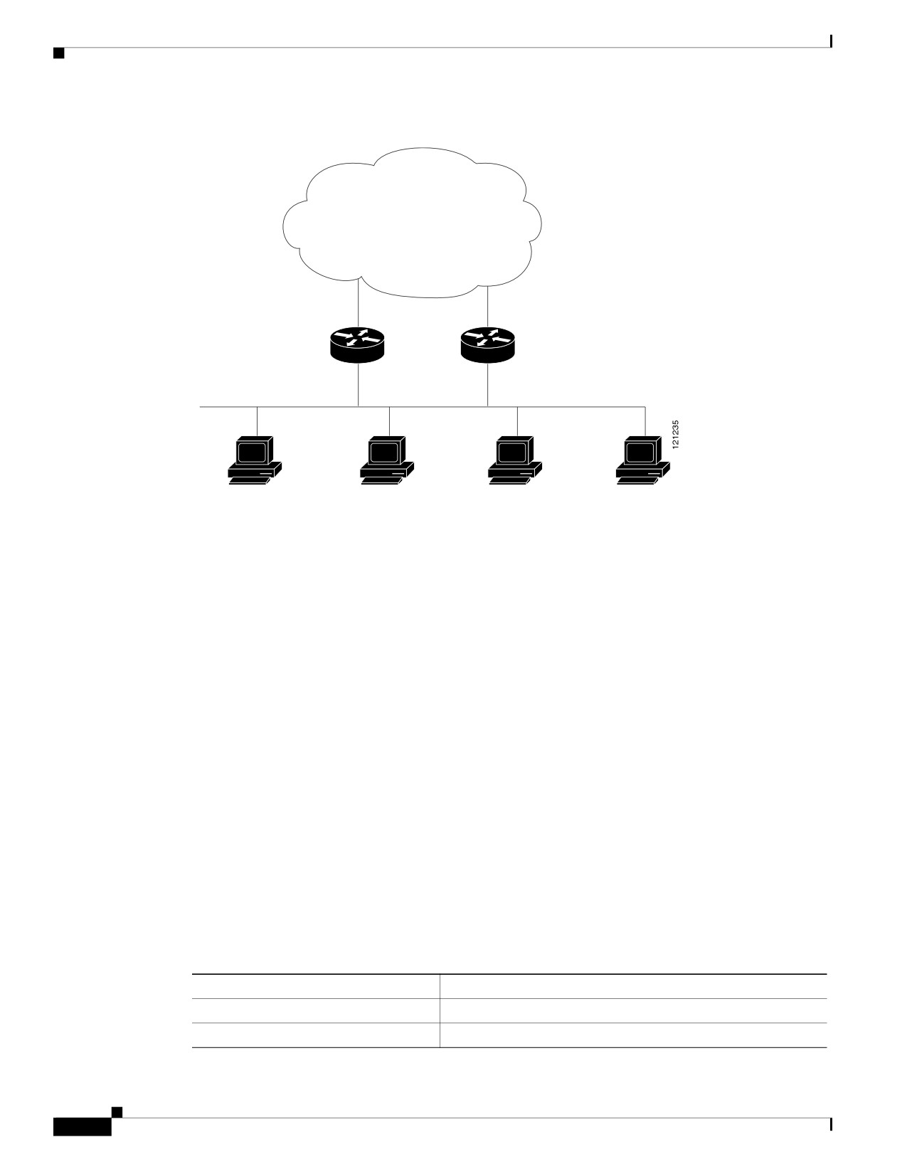
Figure 49-96 shows a segment of a network configured for HSRP. Each router is configured with the
MAC address and IP network address of the virtual router. Instead of configuring hosts on the network
with the IP address of Router A, you configure them with the IP address of the virtual router as their
default router. When Host C sends packets to Host B, it sends them to the MAC address of the virtual
router. If for any reason, Router A stops transferring packets, Router B responds to the virtual IP address
and virtual MAC address and becomes the active router, assuming the active router duties. Host C
continues to use the IP address of the virtual router to address packets destined for Host B, which Router
B now receives and sends to Host B. Until Router A resumes operation, HSRP allows Router B to
provide uninterrupted service to users on Host C’s segment that need to communicate with users on Host
B’s segment and also continues to perform its normal function of handling packets between the Host A
segment and Host B.
Figure 49-96
Typical HSRP Configuration
Host B
172.20.130.5
Active
Virtual
Standby
router
router
router
172.20.128.1
172.20.128.3
172.20.128.2
Router A
Router B
172.20.128.32
172.20.128.55
Host C
Host A
Cisco Industrial Ethernet 4000 Series Switch Software Configuration Guide
-810
Chapter Configuring HSRP and VRRP
Understanding HSRP
HSRP Versions
The switch supports these Hot Standby Redundancy Protocol (HSRP) versions:
• HSRPv1—Version 1 of the HSRP, the default version of HSRP. It has these features:
- The HSRP group number can be from 0 to 255.
- HSRPv1 uses the multicast address 224.0.0.2 to send hello packets, which can conflict with
Cisco Group Management Protocol (CGMP) leave processing. You cannot enable HSRPv1 and
CGMP at the same time; they are mutually exclusive.
• HSRPv2—Version 2 of the HSRP has these features:
- To match the HSRP group number to the VLAN ID of a subinterface, HSRPv2 can use a group
number from 0 to 4095 and a MAC address from 0000.0C9F.F000 to 0000.0C9F.FFFF.
- HSRPv2 uses the multicast address 224.0.0.102 to send hello packets. HSRPv2 and CGMP
leave processing are no longer mutually exclusive, and both can be enabled at the same time.
- HSRPv2 has a different packet format than HRSPv1.
A switch running HSRPv1 cannot identify the physical router that sent a hello packet because
the source MAC address of the router is the virtual MAC address.
HSRPv2 has a different packet format than HSRPv1. A HSRPv2 packet uses the
type-length-value (TLV) format and has a 6-byte identifier field with the MAC address of the
physical router that sent the packet.
If an interface running HSRPv1 gets an HSRPv2 packet, the type field is ignored.
Multiple HSRP
The switch supports Multiple HSRP (MHSRP), an extension of HSRP that allows load sharing between
two or more HSRP groups. You can configure MHSRP to achieve load balancing and to use two or more
standby groups (and paths) from a host network to a server network. In Figure 49-97, half the clients are
configured for Router A, and half the clients are configured for Router B. Together, the configuration
for Routers A and B establishes two HSRP groups. For group 1, Router A is the default active router
because it has the assigned highest priority, and Router B is the standby router. For group 2, Router B is
the default active router because it has the assigned highest priority, and Router A is the standby router.
During normal operation, the two routers share the IP traffic load. When either router becomes
unavailable, the other router becomes active and assumes the packet-transfer functions of the router that
is unavailable.
Note
For MHSRP, you need to enter the standby preempt interface configuration command on the HSRP
interfaces so that if a router fails and then comes back up, preemption restores load sharing.
Cisco Industrial Ethernet 4000 Series Switch Software Configuration Guide
-811
Chapter
Configuring HSRP and VRRP
Configuring HSRP
Figure 49-97
MHSRP Load Sharing
Active router for group 1
Active router for group 2
Standby router for group 2
Standby router for group 1
Router A
Router B
10.0.0.1
10.0.0.2
Client 1
Client 2
Client 3
Client 4
Configuring HSRP
These sections contain this configuration information:
• Default HSRP Configuration, page -812
• HSRP Configuration Guidelines, page -813
• Enabling HSRP, page -814
• Configuring HSRP Priority, page -815
• Configuring MHSRP, page -817
• Configuring HSRP Authentication and Timers, page -818
• Enabling HSRP Support for ICMP Redirect Messages, page -819
• Configuring HSRP Groups and Clustering, page -819
• Troubleshooting HSRP, page -819
Default HSRP Configuration
Table 49-63 shows the default HSRP configuration.
Table 49-63
Default HSRP Configuration
Feature
Default Setting
HSRP version
Version 1
HSRP groups
None configured
Cisco Industrial Ethernet 4000 Series Switch Software Configuration Guide
-812

Chapter Configuring HSRP and VRRP
Configuring HSRP
Table 49-63
Default HSRP Configuration
Feature
Default Setting
Standby group number
0
Standby MAC address
System assigned as: 0000.0c07.acXX, where XX is the HSRP
group number
Standby priority
100
Standby delay
0 (no delay)
Standby track interface priority
10
Standby hello time
3 seconds
Standby holdtime
10 seconds
HSRP Configuration Guidelines
Follow these guidelines when configuring HSRP:
•
HSRP for IPv4 and HSRP for IPv6 are mutually exclusive. You cannot enable both at the same time.
•
HSRPv2 and HSRPv1 are mutually exclusive. HSRPv2 is not interoperable with HSRPv1 on an
interface and the reverse.
•
You can configure up to 32 instances of HSRP groups.
If you configure the same HSRP group number on multiple interfaces, the switch counts each
interface as one instance:
For example, if you configure HSRP group 0 on VLAN 1 and on port 1, the switch counts this as
two instances.
•
In the configuration procedures, the specified interface must be a Layer 3 interface:
- Routed port: a physical port configured as a Layer 3 port by entering the no switchport
interface configuration command.
- SVI: a VLAN interface created by using the interface vlan vlan_id global configuration
command and by default a Layer 3 interface.
- EtherChannel port channel in Layer 3 mode: a port-channel logical interface created by using
the interface port-channel port-channel-number global configuration command and binding
the Ethernet interface into the channel group. For more information, see the “Configuring
Layer 3 EtherChannels” section.
•
All Layer 3 interfaces must have assigned IP addresses.
•
Configure only one instance of an FHRP. The switches support HSRPv1, HSRPv2, and HSRP for
IPv6.
•
The version of an HSRP group can be changed from HSRPv2 to HSRPv1 only if the group number
is less than 256.
•
When configuring group numbers for HSRPv2 and HSRP for IPv6, you must use group numbers in
ranges that are multiples of 256. Valid ranges are 0 to 255, 256 to 511, 512 to 767, 3840 to 4095,
and so on.
Examples of valid and invalid group numbers:
- If you configure groups with the numbers 2, 150, and 225, you cannot configure another group
with the number 3850. It is not in the range of 0 to 255.
Cisco Industrial Ethernet 4000 Series Switch Software Configuration Guide
-813

Chapter
Configuring HSRP and VRRP
Configuring HSRP
- If you configure groups with the numbers 520, 600, and 700, you cannot configure another
group with the number 900. It is not in the range of 512 to 767.
• If you change the HSRP version on an interface, each HSRP group resets because it now has a new
virtual MAC address.
Enabling HSRP
The standby ip interface configuration command activates HSRP on the configured interface. If an IP
address is specified, that address is used as the designated address for the Hot Standby group. If no IP
address is specified, the address is learned through the standby function. You must configure at least one
Layer 3 port on the LAN with the designated address. Configuring an IP address always overrides
another designated address currently in use.
When the standby ip command is enabled on an interface and proxy ARP is enabled, if the interface’s
Hot Standby state is active, proxy ARP requests are answered using the Hot Standby group MAC
address. If the interface is in a different state, proxy ARP responses are suppressed.
Beginning in privileged EXEC mode, follow these steps to create or enable HSRP on a Layer 3 interface:
Command
Purpose
Step
1
configure terminal
Enter global configuration mode.
Step
2
interface interface-id
Enter interface configuration mode, and enter the Layer 3 interface on
which you want to enable HSRP.
Step
3
standby version {1 | 2}
(Optional) Configure the HSRP version on the interface.
•
1— Select HSRPv1.
•
2— Select HSRPv2.
If you do not enter this command or do not specify a keyword, the
interface runs the default HSRP version, HSRP v1.
Step
4
standby [group-number] ip [ip-address
Create (or enable) the HSRP group using its number and virtual IP
[secondary]]
address.
•
(Optional) group-number—The group number on the interface for
which HSRP is being enabled. The range is 0 to 255; the default is 0.
If there is only one HSRP group, you do not need to enter a group
number.
•
(Optional on all but one interface) ip-address—The virtual IP address
of the hot standby router interface. You must enter the virtual IP
address for at least one of the interfaces; it can be learned on the other
interfaces.
•
(Optional) secondary—The IP address is a secondary hot standby
router interface. If neither router is designated as a secondary or
standby router and no priorities are set, the primary IP addresses are
compared and the higher IP address is the active router, with the next
highest as the standby router.
Step
5
end
Return to privileged EXEC mode.
Step
6
show standby [interface-id [group]]
Verify the configuration.
Step
7
copy running-config startup-config
(Optional) Save your entries in the configuration file.
Cisco Industrial Ethernet 4000 Series Switch Software Configuration Guide
-814
Chapter Configuring HSRP and VRRP
Configuring HSRP
Use the no standby [group-number] ip [ip-address] interface configuration command to disable HSRP.
This example shows how to activate HSRP for group 1 on an interface. The IP address used by the hot
standby group is learned by using HSRP.
Note
This procedure is the minimum number of steps required to enable HSRP. Other configuration is
optional.
Switch# configure terminal
Switch(config)# interface gigabitethernet1/1
Switch(config-if)# no switchport
Switch(config-if)# standby 1 ip
Switch(config-if)# end
Switch# show standby
Configuring HSRP Priority
The standby priority, standby preempt, and standby track interface configuration commands are all
used to set characteristics for finding active and standby routers and behavior regarding when a new
active router takes over.
When configuring HSRP priority, follow these guidelines:
•
Assigning a priority allows you to select the active and standby routers. If preemption is enabled,
the router with the highest priority becomes the active router. If priorities are equal, the current
active router does not change.
•
The highest number (1 to 255) represents the highest priority (most likely to become the active
router).
•
When setting the priority, preempt, or both, you must specify at least one keyword (priority,
preempt, or both).
•
The priority of the device can change dynamically if an interface is configured with the standby
track command and another interface on the router goes down.
•
The standby track interface configuration command ties the router hot standby priority to the
availability of its interfaces and is useful for tracking interfaces that are not configured for HSRP.
When a tracked interface fails, the hot standby priority on the device on which tracking has been
configured decreases by 10. If an interface is not tracked, its state changes do not affect the hot
standby priority of the configured device. For each interface configured for hot standby, you can
configure a separate list of interfaces to be tracked.
•
The standby track interface-priority interface configuration command specifies how much to
decrement the hot standby priority when a tracked interface goes down. When the interface comes
back up, the priority is incremented by the same amount.
•
When multiple tracked interfaces are down and interface-priority values have been configured, the
configured priority decrements are cumulative. If tracked interfaces that were not configured with
priority values fail, the default decrement is 10, and it is noncumulative.
•
When routing is first enabled for the interface, it does not have a complete routing table. If it is
configured to preempt, it becomes the active router, even though it is unable to provide adequate
routing services. To solve this problem, configure a delay time to allow the router to update its
routing table.
Cisco Industrial Ethernet 4000 Series Switch Software Configuration Guide
-815

Chapter
Configuring HSRP and VRRP
Configuring HSRP
Beginning in privileged EXEC mode, use one or more of these steps to configure HSRP priority
characteristics on an interface:
Command
Purpose
Step
1
configure terminal
Enter global configuration mode.
Step
2
interface interface-id
Enter interface configuration mode, and enter the HSRP interface on which
you want to set priority.
Step
3
standby [group-number] priority
Set a priority value used in choosing the active router. The range is 1 to 255;
priority [preempt [delay delay]]
the default priority is 100. The highest number represents the highest priority.
•
(Optional) group-number—The group number to which the command
applies.
•
(Optional) preempt—Select so that when the local router has a higher
priority than the active router, it assumes control as the active router.
•
(Optional) delay—Set to cause the local router to postpone taking over the
active role for the shown number of seconds. The range is 0 to
3600(1 hour); the default is 0 (no delay before taking over).
Use the no form of the command to restore the default values.
Step
4
standby [group-number] [priority
Configure the router to preempt, which means that when the local router has
priority] preempt [delay delay]
a higher priority than the active router, it assumes control as the active router.
•
(Optional) group-number—The group number to which the command
applies.
•
(Optional) priority—Enter to set or change the group priority. The range
is 1 to 255; the default is 100.
•
(Optional) delay—Set to cause the local router to postpone taking over the
active role for the number of seconds shown. The range is 0 to 3600
(1 hour); the default is 0 (no delay before taking over).
Use the no form of the command to restore the default values.
Step
5
standby [group-number] track
Configure an interface to track other interfaces so that if one of the other
type number [interface-priority]
interfaces goes down, the device’s Hot Standby priority is lowered.
•
(Optional) group-number—The group number to which the command
applies.
• type—Enter the interface type (combined with interface number) that is
tracked.
• number—Enter the interface number (combined with interface type) that
is tracked.
•
(Optional) interface-priority—Enter the amount by which the hot standby
priority for the router is decremented or incremented when the interface
goes down or comes back up. The default value is 10.
Step
6
end
Return to privileged EXEC mode.
Step
7
show running-config
Verify the configuration of the standby groups.
Step
8
copy running-config
(Optional) Save your entries in the configuration file.
startup-config
Cisco Industrial Ethernet 4000 Series Switch Software Configuration Guide
-816